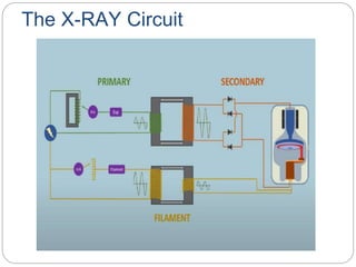
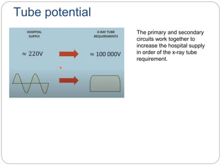
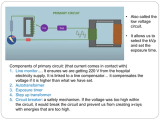
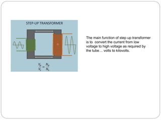
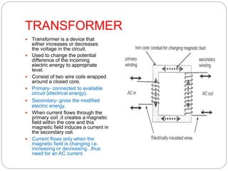
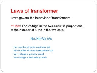
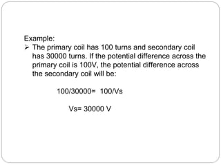
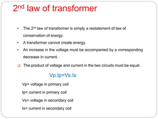
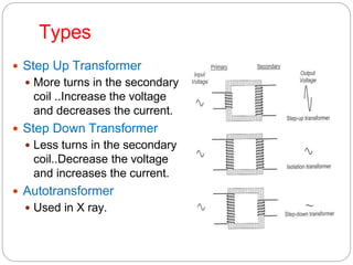
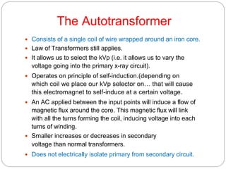
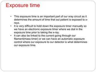
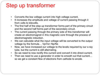
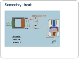
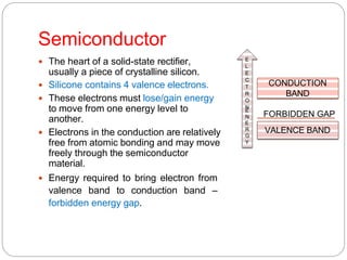
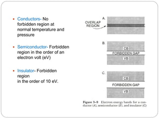
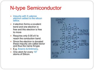
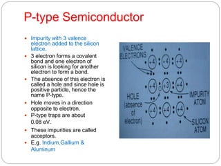
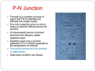
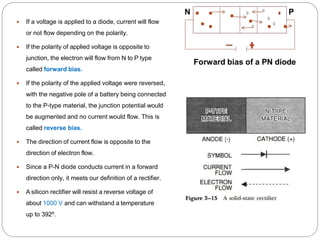
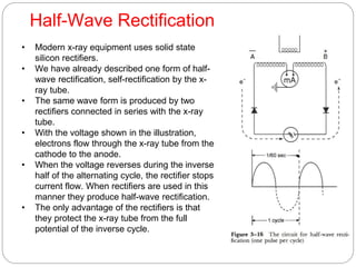
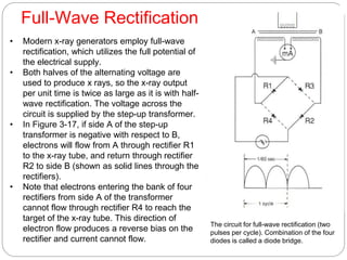
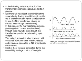
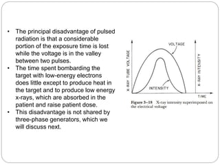
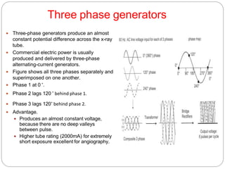
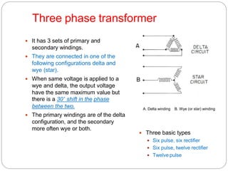
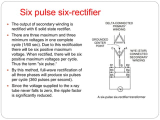
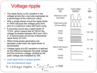
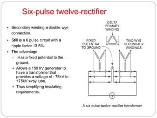
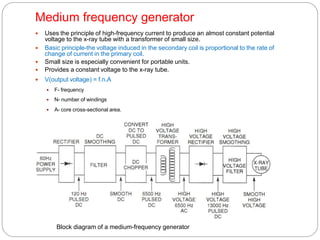
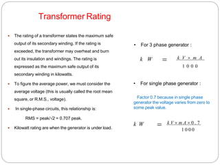
X RAY
GENERATORS
Introduction
 The device that supplies electric power to the x-
ray tube.
 It begins with a source of electrical energy.
 Modifies the supplied energy (230 V) to meet the
needs of x-ray tube.
 The tube requires electrical energy for 2 purposes:
 To boil the electrons from the filament.
 To accelerate these electrons from the cathode to the anode.
X-ray generator
 X-ray generator has a circuit for each of these functions,
refer them as:
1. Filament.
2. High voltage circuits
3. Timer mechanism, which regulates the length of the x-
ray exposure.
 All three circuits are interrelated.
Component
The mechanism of an x-ray generator is continued in 2
separate compartments:
1. Control panel / console
 It may be Simple /complex.
 Allows operatorto select appropriate kVp, mA & exposure time for a
particular x-ray.
 Meters measure the actual mA and kVp during the exposure.
 One exposure button (standby) readies the x-ray tube for
exposure by heating the filament and rotating the anode, and the
other button starts the exposure.
 The timing mechanism terminates the exposure.
2. Transformer assembly
 Grounded metal box filled with oil
 Low voltage transformer for filament circuit.
 High voltage transformer & group of rectifiers for high
voltage circuit.
-the potential difference in these circuits may be as high as
1,50,00 V, so both transformer and rectifier are immersed in
oil.
- The oil serves as an insulator and prevents sparkling
between the various components.
The X-RAY Circuit
Tube potential
The primary and secondary
circuits work together to
increase the hospital supply
in order of the x-ray tube
requirement.
• Also called the
low voltage
circuit.
• It allows us to
select the kVp
and set the
exposure time.
Components of primary circuit: (that current comes in contact with)
1. Line monitor…. It ensures we are getting 220 V from the hospital
electricity supply. It is linked to a line compensator… it compensates the
voltage if it is higher than what we have set.
2. Autotransformer
3. Exposure timer
4. Step up transformer
5. Circuit breaker: a safety mechanism. If the voltage was too high within
the circuit, it would break the circuit and prevent us from creating x-rays
with energies that are too high.
The main function of step up transformer
is to convert the current from low
voltage to high voltage as required by
the tube… volts to kilovolts.
TRANSFORMER
 Transformer is a device that
either increases or decreases
the voltage in the circuit.
 Used to change the potential
difference of the incoming
electric energy to appropriate
level.
 Consist of two wire coils wrapped
around a closed core.
 Primary- connected to available
circuit (electrical energy).
 Secondary- gives the modified
electric energy.
 When current flows through the
primary coil ,it creates a magnetic
field within the core and this
magnetic field induces a current in
the secondary coil.
 Current flows only when the
magnetic field is changing i.e.
increasing or decreasing...thus
need for an AC current.
Laws of transformer
Laws govern the behavior of transformers.
1st law: The voltage in the two circuit is proportional
to the number of turns in the two coils.
Np /Ns=Vp /Vs
Np= number of turns in primary coil
Ns= number of turns in secondary coil
Vp= voltage in primary circuit
Vs= voltage in secondary circuit
Example:
 The primary coil has 100 turns and secondary coil
has 30000 turns. If the potential difference across the
primary coil is 100V, the potential difference across
the secondary coil will be:
100/30000= 100/Vs
Vs= 30000 V
2nd law of transformer
• The 2nd law of transformer is simply a restatement of law of
conservation of energy.
• A transformer cannot create energy.
• An increase in the voltage must be accompanied by a corresponding
decrease in current.
 The product of voltage and current in the two circuits must be equal .
Vp.Ip=Vs.Is
Vp= voltage in primary coil
Ip= current in primary coil
Vs= voltage in secondary coil
Is= current in secondary coil
Types
 Step Up Transformer
 More turns in the secondary
coil ..Increase the voltage
and decreases the current.
 Step Down Transformer
 Less turns in the secondary
coil..Decrease the voltage
and increases the current.
 Autotransformer
 Used in X ray.
 The product of voltage and current is power.
 It is the same on both high and low voltage sides of the transformer.
 The wire in the transformer must be large enough to carry the current
without overheating.
 As a result, high voltage transformers are both large and heavy which
also make them very expensive.
 There are 2 basic circuits in a diagnostic x-ray unit.
 One circuit contains the step up transformer and supplies the high
voltage to the x-ray tube.
 The other circuit contains step down transformer and supplies the
primary voltage for both these circuits.
The Autotransformer
 Consists of a single coil of wire wrapped around an iron core.
 Law of Transformers still applies.
 It allows us to select the kVp (i.e. it allows us to vary the
voltage going into the primary x-ray circuit).
 Operates on principle of self-induction.(depending on
which coil we place our kVp selector on… that will cause
this electromagnet to self-induce at a certain voltage.
 An AC applied between the input points will induce a flow of
magnetic flux around the core. This magnetic flux will link
with all the turns forming the coil, inducing voltage into each
turns of winding.
 Smaller increases or decreases in secondary
voltage than normal transformers.
 Does not electrically isolate primary from secondary circuit.
Exposure time
• This exposure time is an important part of our xray circuit as it
determines the amount of time that out patient is exposed to x-
rays.
• It is very difficult to hold down the exposure timer manually so
we have an electronic exposure timer where we dial in the
exposure time prior to taking the x-ray.
• It can also be linked to the current going through our
filament(mass timer) or we can have an automatic exposure
control where our exposure to our detector is what determines
our exposure time.
Step up transformer
• Converts the low voltage current into high voltage current.
• It increases the amplitude and voltage of current passing through it
from volts to kilovolts.
• The first half of the step up transformer forms part of the primary circuit
and the second half forms part of the secondary circuit.
• The current passing through the primary side of this transformer will
create an electromagnet in this magnetic core through the process of
electromagnetic induction.
• We can calculate what the input voltage will be converted to the output
voltage by the formula… Vp/Vs= Np/Ns
• Now, we have increased our voltage to the levels required by our x-ray
tube, but the current is still alternating.
• So we need to now rectify this current and convert it into direct current.
• Then we need to use a generator in order to smooth out that current…
so we get a constant flow of electrons from cathode to anode.
Secondary circuit
Secondary circuit / High-Voltage Circuit
 Has two transformers
 An autotransformer (kVp selector located in the control panel)
 Step up transformer
 Voltage across the primary coil of the step up transformer can be varied
by selecting the appropriate number of turns in the autotransformer.
 Two meters are placed voltmeter and ammeter.
 The voltmeter is placed in the primary circuit. As the kVp meter
records the selected kVp before the actual exposure begins hence
the name “prereading peak kilovolt meter”.
 The ammeter is placed in the secondary circuit for accurate reading.
 The voltage in this circuit is relatively small and the meter can be
located on the control panel with minimum of insulation.
 The mA meter is in a circuit with a potential difference of up to 150
kilo kVp to minimize the risk of electric shock.
• The secondary circuit uses the process of rectification in order
to change the AC into DC.
• The secondary circuit then supplies both anode and cathode .
• The DC that is created is still fluctuating and now we use the
process of generation in order to smooth out the current and
make sure there is a steady flow of electrons from cathode to
anode.
• 2 rules we need to know:
1. Diode : is a semi conductor that only allows electrons to pass
through it in one direction. (electrons pass through the diode in
the opposite direction to an arrow)
2. Electrons flow only from negative to positive terminal of the
coil.
The electrons flow from the negative terminal of the coil to the
cathode then anode and back to the positive terminal.
Rectification
 Is the process of changing AC into DC .
 Rectifier is a device that allows an electrical current to flow only
in one direction.
 The x-ray tube is a rectifier because current will not flow from
anode to cathode.
 Vacuum tube type (“thermionic diode tubes”) No longer used.
 Solid-state type (smaller/more reliable/longer life)
o E.g. Selenium
After the current is rectified(converted the negative deflections into
positive deflections) it is still alternating. It is fluctuating between high
and no voltage. Now we want to create a smooth tube potential
between cathode and anode…. Here we need the process of
generation.
Generator
Filament Circuit
 Regulates current flow through the filament of x-ray tube.
 The filament is a coiled tungsten wire that emits electrons when it is
heated by this current flow (aka thermionic emission).
 The power to heat the x-ray tube filament is provided by a small step-
down transformer called the “filament transformer”. (not much power is
needed to heat it to the necessary high temperature).
 A variable resistor is used in the primary circuit to regulate the current
flow.
 Precise control of filament heating is critical, because a small variation
in filament current results in a large variation in x-ray tube current.
Filament circuit
Filament circuit has 2 major purposes;
1. To determine the current flowing through the filament
2. To determine which filament we use. ( large and small filament and
changing between the 2 will affect our effective focal spot and eventually
our spatial resolution on our x-ray tube.
1. Select the current flowing through the circuit.
2. Rheostat : a variable resistor
V = I x R (voltage= current x resistance.
Voltage remains the same(constant)
If we increase the resistance, it will decrease the current proportionally and
vice versa, in order to keep the voltage same.
3. Filament: Select the filament (large or small within the focusing cup of
cathode).
4. Step down transformer: reduces the high voltage current to low voltage
current(opposite of that in the primary and secondary circuits).
220 V converted into 7-10 V. A step down transformer that goes into a high
resistance circuit… will lead to an increase in the current.
Depending on the amount of current flowing through the cathode will
determine the number of electrons that are available through the process of
thermionic emission for acceleration towards the anode.(important to
remember that the filament current does not accelerate electrons from cathode
to anode it’s the tube potential that does it… the primary and secondary
circuit.)
Tube potential
Changing the kVp will
increase the tube current
exponentially.
When we increase our
filament current.. From 4.5 to
5, it changes our tube
current in a linear fashion
At low tube currents…
exponential graphs are
seen.. But as tube currents
reach a set point, we see
linear graphs.
After a specific tube current, changing the filament current is
actually a linear relationship… increasing the filament current is
proportional to the increase in tube current. So change in filament
current is proportional to the number of electrons that are available.
Changing the filament current will change the x-ray quantity and do
nothing to the x-ray beam quality.
This change in the x-ray beam quantity is directly proportional to the
change in filament current.
Multiple functions of x-ray tube:
• Convert low voltage to high voltage current
• Convert AC to DC
• Change fluctuating to smooth current
• Select kVp by changing it on primary circuit
• Select exposure time
• Determine the filament current which is directly proportional to the
number of electrons available
• Determine whether to use the large or small filament in the cathode.
All these above changes will change the number of electrons going
from cathode to anode or the energy of those electrons… after which
they are strike at the anode and that where the x-rays are produced.
Semiconductor
 The heart of a solid-state rectifier,
usually a piece of crystalline silicon.
 Silicone contains 4 valence electrons.
 These electrons must lose/gain energy
to move from one energy level to
another.
 Electrons in the conduction are relatively
free from atomic bonding and may move
freely through the semiconductor
material.
 Energy required to bring electron from
valence band to conduction band –
forbidden energy gap.
CONDUCTION
BAND
VALENCE BAND
FORBIDDEN GAP
E
L
E
C
T
R
O
N
E
N
E
R
G
Y
 Conductors- No
forbidden region at
normal temperature and
pressure
 Semiconductor- Forbidden
region in the order of an
electron volt (eV)
 Insulator- Forbidden
region
in the order of 10 eV.
N-type Semiconductor
 Impurity with 5 valence
electron added to the silicon
lattice.
 4 electron forms a covalent
bond and one electron is
free and this electron is free
to move
 Requires only 0.05 eV to
reach the conduction band.
 Since the electron is donated
these impurity are called donor
and thus the name N-type
 E.g. Arsenic & Antimony.
 One atom for every 107
atoms of Silicon.
P-type Semiconductor
 Impurity with 3 valence
electron added to the silicon
lattice.
 3 electron forms a covalent
bond and one electron of
silicon is looking for another
electron to form a bond.
 The absence of this electron is
called a hole and since hole is
positive particle, hence the
name P-type.
 Hole moves in a direction
opposite to electron.
 P-type traps are about
0.08 eV.
 These impurities are called
acceptors.
 E.g. Indium,Gallium &
Aluminum
P-N Junction
 Formed by a complex process in
which the P & N materials are
diffused into single crystal.
 N is rich in electron and p is rich in
holes so electron diffuse across the
junction.
 An electrostatic barrier is formed
that limits the diffusion called
depletion layer.
 Depletion layer has a junction
potential (0.7V in silicon) opposite to
the designation of material.
 The device formed by P-N Junction
is called diode.
• Solid-state rectifiers are diodes.
 If a voltage is applied to a diode, current will flow
or not flow depending on the polarity.
 If the polarity of applied voltage is opposite to
junction, the electron will flow from N to P type
called forward bias.
 If the polarity of the applied voltage were reversed,
with the negative pole of a battery being connected
to the P-type material, the junction potential would
be augmented and no current would flow. This is
called reverse bias.
 The direction of current flow is opposite to the
direction of electron flow.
 Since a P-N diode conducts current in a forward
direction only, it meets our definition of a rectifier.
 A silicon rectifier will resist a reverse voltage of
about 1000 V and can withstand a temperature
up to 392⁰.
N P
Forward bias of a PN diode
Half-Wave Rectification
• Modern x-ray equipment uses solid state
silicon rectifiers.
• We have already described one form of half-
wave rectification, self-rectification by the x-
ray tube.
• The same wave form is produced by two
rectifiers connected in series with the x-ray
tube.
• With the voltage shown in the illustration,
electrons flow through the x-ray tube from the
cathode to the anode.
• When the voltage reverses during the inverse
half of the alternating cycle, the rectifier stops
current flow. When rectifiers are used in this
manner they produce half-wave rectification.
• The only advantage of the rectifiers is that
they protect the x-ray tube from the full
potential of the inverse cycle.
Full-Wave Rectification
• Modern x-ray generators employ full-wave
rectification, which utilizes the full potential of
the electrical supply.
• Both halves of the alternating voltage are
used to produce x rays, so the x-ray output
per unit time is twice as large as it is with half-
wave rectification. The voltage across the
circuit is supplied by the step-up transformer.
• In Figure 3-17, if side A of the step-up
transformer is negative with respect to B,
electrons will flow from A through rectifier R1
to the x-ray tube, and return through rectifier
R2 to side B (shown as solid lines through the
rectifiers).
• Note that electrons entering the bank of four
rectifiers from side A of the transformer
cannot flow through rectifier R4 to reach the
target of the x-ray tube. This direction of
electron flow produces a reverse bias on the
rectifier and current cannot flow.
The circuit for full-wave rectification (two
pulses per cycle). Combination of the four
diodes is called a diode bridge.
• In the following half-cycle, side B of the
transformer becomes negative, and side A
positive.
• Electrons will now reach the filament of the
x-ray tube by flowing from B through rectifier
R3 to the filament and return via rectifier R4
to side A of the transformer (shown as
dashed lines through the rectifiers).
• In this manner, the four rectifiers produce a
pulsating direct current (unidirectional)
through the x-ray tube even though the
transformer supplied an alternating input
current.
• The voltage across the tube, however, still
fluctuates from zero to its maximum level,
and x rays are generated in 120 short bursts
each second.
• Most of the x-rays are generated during the
central high-voltage portion of the cycle.
• The principal disadvantage of pulsed
radiation is that a considerable
portion of the exposure time is lost
while the voltage is in the valley
between two pulses.
• The time spent bombarding the
target with low-energy electrons
does little except to produce heat in
the target and to produce low energy
x-rays, which are absorbed in the
patient and raise patient dose.
• This disadvantage is not shared by
three-phase generators, which we
will discuss next.
Three phase generators
 Three-phase generators produce an almost
constant potential difference across the x-ray
tube.
 Commercial electric power is usually
produced and delivered by three-phase
alternating-current generators.
 Figure shows all three phases separately and
superimposed on one another.
 Phase 1 at 0 ˚.
 Phase 2 lags 120 ˚ behind phase 1.
 Phase 3 lags 120˚ behind phase 2.
 Advantage.
 Produces an almost constant voltage,
because there are no deep valleys
between pulse.
 Higher tube rating (2000mA) for extremely
short exposure excellent for angiography.
Three phase transformer
 It has 3 sets of primary and
secondary windings.
 They are connected in one of the
following configurations delta and
wye (star).
 When same voltage is applied to a
wye and delta, the output voltage
have the same maximum value but
there is a 30˚ shift in the phase
between the two.
 The primary windings are of the delta
configuration, and the secondary
more often wye or both.
 Three basic types
 Six pulse, six rectifier
 Six pulse, twelve rectifier
 Twelve pulse
A. Delta winding B. Wye (or star) winding
Six pulse six-rectifier
 The output of secondary winding is
rectified with 6 solid state rectifier.
 There are three maximum and three
minimum voltages in one complete
cycle (1/60 sec). Due to this rectification
there will be six positive maximum
voltage. When rectified, there will be six
positive maximum voltages per cycle.
Thus the term "six pulse.“
 By this method, full-wave rectification of
all three phases will produce six pulses
per cycle (360 pulses per second).
 Since the voltage supplied to the x-ray
tube never falls to zero, the ripple factor
is significantly reduced. A six-pulse six-rectifier transformer
Voltage ripple
 The ripple factor is the variation in the
voltage across the x-ray tube expressed as
a percentage of the maximum value.
 With a single-phase circuit the ripple factor
is 100% because the voltage goes from
zero to a maximum value with each cycle.
 A six-pulse circuit has a ripple factor of
13.5%, which means that at 100 kV the
voltage fluctuates between 86.5 and 100 k
V. A twelve-pulse circuit has a theoretical
ripple factor of 3.5%.
 When three-phase generators are
operated under load, the ripple factor is
accentuated.
 Voltage ripple of a DC waveform is defined
as the difference between the peak voltage
and the minimum voltage, divided by the
peak voltage and multiplied by 100.
 Load ripple factor is always greater
than the theoretical ripple.
 1 0 0
V m a x
 V m in
% v o l t a g e ripple 
V m a x
Six-pulse twelve-rectifier
 Secondary winding a double wye
connection.
 Still is a 6 pulse circuit with a
ripple factor 13.5%.
 The advantage
 Has a fixed potential to the
ground.
 Allows a 150 kV generator to
have a transformer that
provides a voltage of - 75kV to
+75kV x-ray tube.
 Thus simplifying insulating
requirements.
A six-pulse twelve-rectifier transformer
Twelve-pulse
 A twelve-pulse transformer looks similar to
the six-pulse twelve-rectifier transformer. The
difference is that the secondary is not a
double wye connection; it is a wye and a
delta connection.
 Secondary winding is a wye and a delta
connection.
 Output of delta will lag wye by 30˚.
 So output of one will fill in the ripple of
other.
 Thus a twelve-pulse.
 Theoretical ripple is reduced to 3.5% with a
load ripple factor of 5%.
 Modern generators are designed on the
principle of one-wye and one-delta
configuration in the windings of the high-
voltage transformer. A twelve-pulse three-phase transformer
Power Storage Generator
 When mobile radiographic equipment is taken to a patient's
room, the available power supply is often inadequate.
 These provide a means of supplying power for the x- ray tube
independent of external power supply.
 Useful for mobile units
 Two types:
 Capacitor discharge generator
 Battery-powered generator
Capacitor discharge generator
 Electrical device for storing
charge, or electron.
 Charged by the use of a step up
transformer and rectifier.
 Discharged through x-ray tube,
usually grid controlled.
 These provides very short mA
(up to 500mA) for very short
exposure time
 Disadvantage –falling of kV during
exposure about 1kV for 1mAs –
limited usefulness in radiography of
thick body parts.
 Must be charged immediately prior
to use.
Battery powered generator
 A standard power supply is used to
charge large capacity nickel-cadmium
batteries. The fully charged unit can then
operate completely independent of
connection to an outside power supply.
 Can operate completely independent of
connection to outside power supply.
 Advantages:
 Store considerable energy to generate x-
rays. (10,000 mAs)
 To make exposures independent of power
supply.
 The battery unit supplies a constant output
of kV and mA throughout the exposure.
Medium frequency generator
 Uses the principle of high-frequency current to produce an almost constant potential
voltage to the x-ray tube with a transformer of small size.
 Basic principle-the voltage induced in the secondary coil is proportional to the rate of
change of current in the primary coil.
 Small size is especially convenient for portable units.
 Provides a constant voltage to the x-ray tube.
 V(output voltage) = f.n.A
 F- frequency
 N- number of windings
 A- core cross-sectional area.
Block diagram of a medium-frequency generator
Transformer Rating
 The rating of a transformer states the maximum safe
output of its secondary winding. If the rating is
exceeded, the transformer may overheat and burn
out its insulation and windings. The rating is
expressed as the maximum safe output of its
secondary winding in kilowatts.
 To figure the average power, we must consider the
average voltage (this is usually called the root mean
square, or R.M.S., voltage).
 In single-phase circuits, this relationship is:
RMS = peak/√2 = 0.707 peak.
 Kilowatt rating are when the generator is under load.
• For 3 phase generator :
k W  k V  m A
1 0 0 0
• For single phase generator :
Factor 0.7 because in single phase
generator the voltage varies from zero to
some peak value.
k W  k V  m A  0 . 7
1 0 0 0
Exposure Switching
 A device that turns the high voltage applied to the
x-ray tube on and off.
 Should switch off the current in the circuit very
rapidly and remove all the energy that is stored in
the voltage smoothing networks.
 Two categories of switching
 Primary Switching
 Secondary Switching
Primary Switching
 Occurs in primary circuit.
 Most general purpose 3 phase units.
 Three types:
 Electromechanical contractors
 Thyratrons
 Solid state silicon controlled rectifiers
 Silicon Controlled rectifier/Thyristers
 Electrons can easily flow from N to P
 Will not flow from P to N
 A small positive voltage (logical signal) applied at
gate, the reverse bias at the PN junction is
overcome and electron flow through the thyrister.
 The response is instantaneous so useful when
fast switching is necessary.
 The electrons will not flow from anode to cathode
because of the 2 PN Junction.
Secondary Switching
 Occurs in the secondary circuit.
 Used in units designed for rapid, repetitive exposure or
where short exposure is needed.
 Uses in Angiography and cineflurography.
 Switches in the high voltage circuit must prevent high-voltage
breakdown, so proper insulation.
 Two types
 Triode vaccum tubes.
 Grid-controlled x-ray tubes.
Falling Load Generators
 To produce an x-ray exposure in the
shortest possible exposure time at
its maximum kilowatt rating during
the entire exposure.
 They give shorter exposure time
then with a fixed tube mA
technique.
 Delivers the maximum
possible mA for the selected
kVp by considering the
instantaneous heat load
characteristics of the x-ray tube
 Continuously reduces the
power as the exposure
continues.
 Used with automatic
exposure generator where
simple operator controls are
desired.
mA sec mAs
600 0.05 30
500 0.15 75
400 0.1 40
300 0.2 60
Total 0.5 205
Using falling load principle
Exposure Timers
 To control the length of an x-ray exposure.
 Four basic types:
1. Mechanical timers(Rarely used today)
2. Electronic timers
3. Automatic exposure control(phototimers)
4. Pulse-counting timers(Count voltage pulse of high frequency)
Electronic timers
 Length of x-ray exposure is determined by the time
required to charge a capacitor through a selected
resistance.
 Exposure button starts the exposure and also starts
charging the capacitor.
 Exposure is terminated when the capacitor is charged
to a value necessary to turn on associated electronic
circuit.
 Subjected to human error.
Automatic Exposure control (phototimer)
 Have been developed to eliminate human error.
 Measures the amount of radiation required to produce the
correct exposure for a radiographic examination.
 Goal - to produce a satisfactory radiograph with each attempt
and reliable reproduction.
 Essential elements – a device that can detect radiation and in
response to this radiation produce a small electric current.
 Three types:
1. Photomultiplier detector
2. Ionization chambers ( ionization of gas)
3. Solid-state detector (PN Junction technique)
 Can be located in front of the cassette ( Entrance
type) or behind the cassette (Exit type).
Photomultiplier Phototimers
Photomultiplier automatic exposure control (phototimer)
This is the most common type of
automatic exposure control.
The detector is made of lucite, which
is a material that can transmit light.
The lucite is coated with one or more
(commonly three) areas of a
phosphor that will emit light when
irradiated with x-rays(these lucite
detectors are usually called lucite
paddles). Lucite serves two
functions: it is the support that holds
the fluorescent screen or screens,
and it transmits light to the
photomultiplier tube so that the
photomultiplier tube may be kept out
of the x-ray field (the photomultiplier
tube would produce an image on the
radiograph)
Phototimers
Summary
• An x-ray generator supplies electrical energy to the x-ray tube and regulates
the length of the radiographic exposure.
• The x-ray tube requires two sources of energy, one to heat the filament and
the other to accelerate electrons between the cathode and anode.
• The filament circuit contains a variable resistance, which is the current
selector, and a step-down transformer.
• The cathode-anode circuit, called the high-voltage circuit, contains an
autotransformer and a step-up transformer. The autotransformer serves as
the kVp selector.
• The incoming electrical supply to the x-ray generator has an alternating
potential.
• Rectifiers are devices (usually silicon diodes) that transmit a current in only
one direction.
• Single-phase generators may have half-wave rectification (60 pulses per
second).
• Three-phase generators may be six-pulse (360 pulses per second) with
a theoretical ripple factor of 1 3.5%, or twelve-pulse (720 pulses per
second) with a ripple factor of 3.5%.
• Special types of generators include capacitor-discharge generators,
battery-powered generators, medium-frequency generators, and falling
load generators.
• Transformers are given a rating that indicates the maximum safe output
of the secondary windings. Such ratings are expressed as the kilowatt
rating.
• Exposure switching may be primary switching or secondary switching.
Almost all general purpose generators use primary switching.
• Secondary switching requires use of triode vacuum tubes or grid-
controlled x-ray tubes, and is used for fast, repetitive exposures.
• Exposure timers include mechanical timers (obsolete), electronic
timers, automatic exposure controls (phototimers), and pulse-counting
timers.
• Automatic exposure control may be achieved with photomultiplier
detectors, ionization chambers, or solid-state detectors.
Summary
Thank
you.

X ray Generator physics behind x ray generation.ppt

  • 1.
  • 2.
    Introduction  The devicethat supplies electric power to the x- ray tube.  It begins with a source of electrical energy.  Modifies the supplied energy (230 V) to meet the needs of x-ray tube.  The tube requires electrical energy for 2 purposes:  To boil the electrons from the filament.  To accelerate these electrons from the cathode to the anode.
  • 3.
    X-ray generator  X-raygenerator has a circuit for each of these functions, refer them as: 1. Filament. 2. High voltage circuits 3. Timer mechanism, which regulates the length of the x- ray exposure.  All three circuits are interrelated.
  • 4.
    Component The mechanism ofan x-ray generator is continued in 2 separate compartments: 1. Control panel / console  It may be Simple /complex.  Allows operatorto select appropriate kVp, mA & exposure time for a particular x-ray.  Meters measure the actual mA and kVp during the exposure.  One exposure button (standby) readies the x-ray tube for exposure by heating the filament and rotating the anode, and the other button starts the exposure.  The timing mechanism terminates the exposure.
  • 5.
    2. Transformer assembly Grounded metal box filled with oil  Low voltage transformer for filament circuit.  High voltage transformer & group of rectifiers for high voltage circuit. -the potential difference in these circuits may be as high as 1,50,00 V, so both transformer and rectifier are immersed in oil. - The oil serves as an insulator and prevents sparkling between the various components.
  • 6.
  • 7.
    Tube potential The primaryand secondary circuits work together to increase the hospital supply in order of the x-ray tube requirement.
  • 8.
    • Also calledthe low voltage circuit. • It allows us to select the kVp and set the exposure time. Components of primary circuit: (that current comes in contact with) 1. Line monitor…. It ensures we are getting 220 V from the hospital electricity supply. It is linked to a line compensator… it compensates the voltage if it is higher than what we have set. 2. Autotransformer 3. Exposure timer 4. Step up transformer 5. Circuit breaker: a safety mechanism. If the voltage was too high within the circuit, it would break the circuit and prevent us from creating x-rays with energies that are too high.
  • 9.
    The main functionof step up transformer is to convert the current from low voltage to high voltage as required by the tube… volts to kilovolts.
  • 10.
    TRANSFORMER  Transformer isa device that either increases or decreases the voltage in the circuit.  Used to change the potential difference of the incoming electric energy to appropriate level.  Consist of two wire coils wrapped around a closed core.  Primary- connected to available circuit (electrical energy).  Secondary- gives the modified electric energy.  When current flows through the primary coil ,it creates a magnetic field within the core and this magnetic field induces a current in the secondary coil.  Current flows only when the magnetic field is changing i.e. increasing or decreasing...thus need for an AC current.
  • 11.
    Laws of transformer Lawsgovern the behavior of transformers. 1st law: The voltage in the two circuit is proportional to the number of turns in the two coils. Np /Ns=Vp /Vs Np= number of turns in primary coil Ns= number of turns in secondary coil Vp= voltage in primary circuit Vs= voltage in secondary circuit
  • 12.
    Example:  The primarycoil has 100 turns and secondary coil has 30000 turns. If the potential difference across the primary coil is 100V, the potential difference across the secondary coil will be: 100/30000= 100/Vs Vs= 30000 V
  • 13.
    2nd law oftransformer • The 2nd law of transformer is simply a restatement of law of conservation of energy. • A transformer cannot create energy. • An increase in the voltage must be accompanied by a corresponding decrease in current.  The product of voltage and current in the two circuits must be equal . Vp.Ip=Vs.Is Vp= voltage in primary coil Ip= current in primary coil Vs= voltage in secondary coil Is= current in secondary coil
  • 14.
    Types  Step UpTransformer  More turns in the secondary coil ..Increase the voltage and decreases the current.  Step Down Transformer  Less turns in the secondary coil..Decrease the voltage and increases the current.  Autotransformer  Used in X ray.
  • 15.
     The productof voltage and current is power.  It is the same on both high and low voltage sides of the transformer.  The wire in the transformer must be large enough to carry the current without overheating.  As a result, high voltage transformers are both large and heavy which also make them very expensive.  There are 2 basic circuits in a diagnostic x-ray unit.  One circuit contains the step up transformer and supplies the high voltage to the x-ray tube.  The other circuit contains step down transformer and supplies the primary voltage for both these circuits.
  • 16.
    The Autotransformer  Consistsof a single coil of wire wrapped around an iron core.  Law of Transformers still applies.  It allows us to select the kVp (i.e. it allows us to vary the voltage going into the primary x-ray circuit).  Operates on principle of self-induction.(depending on which coil we place our kVp selector on… that will cause this electromagnet to self-induce at a certain voltage.  An AC applied between the input points will induce a flow of magnetic flux around the core. This magnetic flux will link with all the turns forming the coil, inducing voltage into each turns of winding.  Smaller increases or decreases in secondary voltage than normal transformers.  Does not electrically isolate primary from secondary circuit.
  • 17.
    Exposure time • Thisexposure time is an important part of our xray circuit as it determines the amount of time that out patient is exposed to x- rays. • It is very difficult to hold down the exposure timer manually so we have an electronic exposure timer where we dial in the exposure time prior to taking the x-ray. • It can also be linked to the current going through our filament(mass timer) or we can have an automatic exposure control where our exposure to our detector is what determines our exposure time.
  • 18.
    Step up transformer •Converts the low voltage current into high voltage current. • It increases the amplitude and voltage of current passing through it from volts to kilovolts. • The first half of the step up transformer forms part of the primary circuit and the second half forms part of the secondary circuit. • The current passing through the primary side of this transformer will create an electromagnet in this magnetic core through the process of electromagnetic induction. • We can calculate what the input voltage will be converted to the output voltage by the formula… Vp/Vs= Np/Ns • Now, we have increased our voltage to the levels required by our x-ray tube, but the current is still alternating. • So we need to now rectify this current and convert it into direct current. • Then we need to use a generator in order to smooth out that current… so we get a constant flow of electrons from cathode to anode.
  • 19.
  • 20.
    Secondary circuit /High-Voltage Circuit  Has two transformers  An autotransformer (kVp selector located in the control panel)  Step up transformer  Voltage across the primary coil of the step up transformer can be varied by selecting the appropriate number of turns in the autotransformer.  Two meters are placed voltmeter and ammeter.  The voltmeter is placed in the primary circuit. As the kVp meter records the selected kVp before the actual exposure begins hence the name “prereading peak kilovolt meter”.  The ammeter is placed in the secondary circuit for accurate reading.  The voltage in this circuit is relatively small and the meter can be located on the control panel with minimum of insulation.  The mA meter is in a circuit with a potential difference of up to 150 kilo kVp to minimize the risk of electric shock.
  • 21.
    • The secondarycircuit uses the process of rectification in order to change the AC into DC. • The secondary circuit then supplies both anode and cathode . • The DC that is created is still fluctuating and now we use the process of generation in order to smooth out the current and make sure there is a steady flow of electrons from cathode to anode. • 2 rules we need to know: 1. Diode : is a semi conductor that only allows electrons to pass through it in one direction. (electrons pass through the diode in the opposite direction to an arrow) 2. Electrons flow only from negative to positive terminal of the coil. The electrons flow from the negative terminal of the coil to the cathode then anode and back to the positive terminal.
  • 22.
    Rectification  Is theprocess of changing AC into DC .  Rectifier is a device that allows an electrical current to flow only in one direction.  The x-ray tube is a rectifier because current will not flow from anode to cathode.  Vacuum tube type (“thermionic diode tubes”) No longer used.  Solid-state type (smaller/more reliable/longer life) o E.g. Selenium After the current is rectified(converted the negative deflections into positive deflections) it is still alternating. It is fluctuating between high and no voltage. Now we want to create a smooth tube potential between cathode and anode…. Here we need the process of generation.
  • 23.
  • 24.
    Filament Circuit  Regulatescurrent flow through the filament of x-ray tube.  The filament is a coiled tungsten wire that emits electrons when it is heated by this current flow (aka thermionic emission).  The power to heat the x-ray tube filament is provided by a small step- down transformer called the “filament transformer”. (not much power is needed to heat it to the necessary high temperature).  A variable resistor is used in the primary circuit to regulate the current flow.  Precise control of filament heating is critical, because a small variation in filament current results in a large variation in x-ray tube current.
  • 25.
    Filament circuit Filament circuithas 2 major purposes; 1. To determine the current flowing through the filament 2. To determine which filament we use. ( large and small filament and changing between the 2 will affect our effective focal spot and eventually our spatial resolution on our x-ray tube.
  • 26.
    1. Select thecurrent flowing through the circuit. 2. Rheostat : a variable resistor V = I x R (voltage= current x resistance. Voltage remains the same(constant) If we increase the resistance, it will decrease the current proportionally and vice versa, in order to keep the voltage same. 3. Filament: Select the filament (large or small within the focusing cup of cathode). 4. Step down transformer: reduces the high voltage current to low voltage current(opposite of that in the primary and secondary circuits). 220 V converted into 7-10 V. A step down transformer that goes into a high resistance circuit… will lead to an increase in the current. Depending on the amount of current flowing through the cathode will determine the number of electrons that are available through the process of thermionic emission for acceleration towards the anode.(important to remember that the filament current does not accelerate electrons from cathode to anode it’s the tube potential that does it… the primary and secondary circuit.)
  • 27.
    Tube potential Changing thekVp will increase the tube current exponentially. When we increase our filament current.. From 4.5 to 5, it changes our tube current in a linear fashion At low tube currents… exponential graphs are seen.. But as tube currents reach a set point, we see linear graphs. After a specific tube current, changing the filament current is actually a linear relationship… increasing the filament current is proportional to the increase in tube current. So change in filament current is proportional to the number of electrons that are available.
  • 28.
    Changing the filamentcurrent will change the x-ray quantity and do nothing to the x-ray beam quality. This change in the x-ray beam quantity is directly proportional to the change in filament current. Multiple functions of x-ray tube: • Convert low voltage to high voltage current • Convert AC to DC • Change fluctuating to smooth current • Select kVp by changing it on primary circuit • Select exposure time • Determine the filament current which is directly proportional to the number of electrons available • Determine whether to use the large or small filament in the cathode. All these above changes will change the number of electrons going from cathode to anode or the energy of those electrons… after which they are strike at the anode and that where the x-rays are produced.
  • 29.
    Semiconductor  The heartof a solid-state rectifier, usually a piece of crystalline silicon.  Silicone contains 4 valence electrons.  These electrons must lose/gain energy to move from one energy level to another.  Electrons in the conduction are relatively free from atomic bonding and may move freely through the semiconductor material.  Energy required to bring electron from valence band to conduction band – forbidden energy gap. CONDUCTION BAND VALENCE BAND FORBIDDEN GAP E L E C T R O N E N E R G Y
  • 30.
     Conductors- No forbiddenregion at normal temperature and pressure  Semiconductor- Forbidden region in the order of an electron volt (eV)  Insulator- Forbidden region in the order of 10 eV.
  • 31.
    N-type Semiconductor  Impuritywith 5 valence electron added to the silicon lattice.  4 electron forms a covalent bond and one electron is free and this electron is free to move  Requires only 0.05 eV to reach the conduction band.  Since the electron is donated these impurity are called donor and thus the name N-type  E.g. Arsenic & Antimony.  One atom for every 107 atoms of Silicon.
  • 32.
    P-type Semiconductor  Impuritywith 3 valence electron added to the silicon lattice.  3 electron forms a covalent bond and one electron of silicon is looking for another electron to form a bond.  The absence of this electron is called a hole and since hole is positive particle, hence the name P-type.  Hole moves in a direction opposite to electron.  P-type traps are about 0.08 eV.  These impurities are called acceptors.  E.g. Indium,Gallium & Aluminum
  • 33.
    P-N Junction  Formedby a complex process in which the P & N materials are diffused into single crystal.  N is rich in electron and p is rich in holes so electron diffuse across the junction.  An electrostatic barrier is formed that limits the diffusion called depletion layer.  Depletion layer has a junction potential (0.7V in silicon) opposite to the designation of material.  The device formed by P-N Junction is called diode. • Solid-state rectifiers are diodes.
  • 34.
     If avoltage is applied to a diode, current will flow or not flow depending on the polarity.  If the polarity of applied voltage is opposite to junction, the electron will flow from N to P type called forward bias.  If the polarity of the applied voltage were reversed, with the negative pole of a battery being connected to the P-type material, the junction potential would be augmented and no current would flow. This is called reverse bias.  The direction of current flow is opposite to the direction of electron flow.  Since a P-N diode conducts current in a forward direction only, it meets our definition of a rectifier.  A silicon rectifier will resist a reverse voltage of about 1000 V and can withstand a temperature up to 392⁰. N P Forward bias of a PN diode
  • 35.
    Half-Wave Rectification • Modernx-ray equipment uses solid state silicon rectifiers. • We have already described one form of half- wave rectification, self-rectification by the x- ray tube. • The same wave form is produced by two rectifiers connected in series with the x-ray tube. • With the voltage shown in the illustration, electrons flow through the x-ray tube from the cathode to the anode. • When the voltage reverses during the inverse half of the alternating cycle, the rectifier stops current flow. When rectifiers are used in this manner they produce half-wave rectification. • The only advantage of the rectifiers is that they protect the x-ray tube from the full potential of the inverse cycle.
  • 36.
    Full-Wave Rectification • Modernx-ray generators employ full-wave rectification, which utilizes the full potential of the electrical supply. • Both halves of the alternating voltage are used to produce x rays, so the x-ray output per unit time is twice as large as it is with half- wave rectification. The voltage across the circuit is supplied by the step-up transformer. • In Figure 3-17, if side A of the step-up transformer is negative with respect to B, electrons will flow from A through rectifier R1 to the x-ray tube, and return through rectifier R2 to side B (shown as solid lines through the rectifiers). • Note that electrons entering the bank of four rectifiers from side A of the transformer cannot flow through rectifier R4 to reach the target of the x-ray tube. This direction of electron flow produces a reverse bias on the rectifier and current cannot flow. The circuit for full-wave rectification (two pulses per cycle). Combination of the four diodes is called a diode bridge.
  • 37.
    • In thefollowing half-cycle, side B of the transformer becomes negative, and side A positive. • Electrons will now reach the filament of the x-ray tube by flowing from B through rectifier R3 to the filament and return via rectifier R4 to side A of the transformer (shown as dashed lines through the rectifiers). • In this manner, the four rectifiers produce a pulsating direct current (unidirectional) through the x-ray tube even though the transformer supplied an alternating input current. • The voltage across the tube, however, still fluctuates from zero to its maximum level, and x rays are generated in 120 short bursts each second. • Most of the x-rays are generated during the central high-voltage portion of the cycle.
  • 38.
    • The principaldisadvantage of pulsed radiation is that a considerable portion of the exposure time is lost while the voltage is in the valley between two pulses. • The time spent bombarding the target with low-energy electrons does little except to produce heat in the target and to produce low energy x-rays, which are absorbed in the patient and raise patient dose. • This disadvantage is not shared by three-phase generators, which we will discuss next.
  • 39.
    Three phase generators Three-phase generators produce an almost constant potential difference across the x-ray tube.  Commercial electric power is usually produced and delivered by three-phase alternating-current generators.  Figure shows all three phases separately and superimposed on one another.  Phase 1 at 0 ˚.  Phase 2 lags 120 ˚ behind phase 1.  Phase 3 lags 120˚ behind phase 2.  Advantage.  Produces an almost constant voltage, because there are no deep valleys between pulse.  Higher tube rating (2000mA) for extremely short exposure excellent for angiography.
  • 40.
    Three phase transformer It has 3 sets of primary and secondary windings.  They are connected in one of the following configurations delta and wye (star).  When same voltage is applied to a wye and delta, the output voltage have the same maximum value but there is a 30˚ shift in the phase between the two.  The primary windings are of the delta configuration, and the secondary more often wye or both.  Three basic types  Six pulse, six rectifier  Six pulse, twelve rectifier  Twelve pulse A. Delta winding B. Wye (or star) winding
  • 41.
    Six pulse six-rectifier The output of secondary winding is rectified with 6 solid state rectifier.  There are three maximum and three minimum voltages in one complete cycle (1/60 sec). Due to this rectification there will be six positive maximum voltage. When rectified, there will be six positive maximum voltages per cycle. Thus the term "six pulse.“  By this method, full-wave rectification of all three phases will produce six pulses per cycle (360 pulses per second).  Since the voltage supplied to the x-ray tube never falls to zero, the ripple factor is significantly reduced. A six-pulse six-rectifier transformer
  • 42.
    Voltage ripple  Theripple factor is the variation in the voltage across the x-ray tube expressed as a percentage of the maximum value.  With a single-phase circuit the ripple factor is 100% because the voltage goes from zero to a maximum value with each cycle.  A six-pulse circuit has a ripple factor of 13.5%, which means that at 100 kV the voltage fluctuates between 86.5 and 100 k V. A twelve-pulse circuit has a theoretical ripple factor of 3.5%.  When three-phase generators are operated under load, the ripple factor is accentuated.  Voltage ripple of a DC waveform is defined as the difference between the peak voltage and the minimum voltage, divided by the peak voltage and multiplied by 100.  Load ripple factor is always greater than the theoretical ripple.  1 0 0 V m a x  V m in % v o l t a g e ripple  V m a x
  • 43.
    Six-pulse twelve-rectifier  Secondarywinding a double wye connection.  Still is a 6 pulse circuit with a ripple factor 13.5%.  The advantage  Has a fixed potential to the ground.  Allows a 150 kV generator to have a transformer that provides a voltage of - 75kV to +75kV x-ray tube.  Thus simplifying insulating requirements. A six-pulse twelve-rectifier transformer
  • 44.
    Twelve-pulse  A twelve-pulsetransformer looks similar to the six-pulse twelve-rectifier transformer. The difference is that the secondary is not a double wye connection; it is a wye and a delta connection.  Secondary winding is a wye and a delta connection.  Output of delta will lag wye by 30˚.  So output of one will fill in the ripple of other.  Thus a twelve-pulse.  Theoretical ripple is reduced to 3.5% with a load ripple factor of 5%.  Modern generators are designed on the principle of one-wye and one-delta configuration in the windings of the high- voltage transformer. A twelve-pulse three-phase transformer
  • 45.
    Power Storage Generator When mobile radiographic equipment is taken to a patient's room, the available power supply is often inadequate.  These provide a means of supplying power for the x- ray tube independent of external power supply.  Useful for mobile units  Two types:  Capacitor discharge generator  Battery-powered generator
  • 46.
    Capacitor discharge generator Electrical device for storing charge, or electron.  Charged by the use of a step up transformer and rectifier.  Discharged through x-ray tube, usually grid controlled.  These provides very short mA (up to 500mA) for very short exposure time  Disadvantage –falling of kV during exposure about 1kV for 1mAs – limited usefulness in radiography of thick body parts.  Must be charged immediately prior to use.
  • 47.
    Battery powered generator A standard power supply is used to charge large capacity nickel-cadmium batteries. The fully charged unit can then operate completely independent of connection to an outside power supply.  Can operate completely independent of connection to outside power supply.  Advantages:  Store considerable energy to generate x- rays. (10,000 mAs)  To make exposures independent of power supply.  The battery unit supplies a constant output of kV and mA throughout the exposure.
  • 48.
    Medium frequency generator Uses the principle of high-frequency current to produce an almost constant potential voltage to the x-ray tube with a transformer of small size.  Basic principle-the voltage induced in the secondary coil is proportional to the rate of change of current in the primary coil.  Small size is especially convenient for portable units.  Provides a constant voltage to the x-ray tube.  V(output voltage) = f.n.A  F- frequency  N- number of windings  A- core cross-sectional area. Block diagram of a medium-frequency generator
  • 49.
    Transformer Rating  Therating of a transformer states the maximum safe output of its secondary winding. If the rating is exceeded, the transformer may overheat and burn out its insulation and windings. The rating is expressed as the maximum safe output of its secondary winding in kilowatts.  To figure the average power, we must consider the average voltage (this is usually called the root mean square, or R.M.S., voltage).  In single-phase circuits, this relationship is: RMS = peak/√2 = 0.707 peak.  Kilowatt rating are when the generator is under load. • For 3 phase generator : k W  k V  m A 1 0 0 0 • For single phase generator : Factor 0.7 because in single phase generator the voltage varies from zero to some peak value. k W  k V  m A  0 . 7 1 0 0 0
  • 50.
    Exposure Switching  Adevice that turns the high voltage applied to the x-ray tube on and off.  Should switch off the current in the circuit very rapidly and remove all the energy that is stored in the voltage smoothing networks.  Two categories of switching  Primary Switching  Secondary Switching
  • 51.
    Primary Switching  Occursin primary circuit.  Most general purpose 3 phase units.  Three types:  Electromechanical contractors  Thyratrons  Solid state silicon controlled rectifiers  Silicon Controlled rectifier/Thyristers  Electrons can easily flow from N to P  Will not flow from P to N  A small positive voltage (logical signal) applied at gate, the reverse bias at the PN junction is overcome and electron flow through the thyrister.  The response is instantaneous so useful when fast switching is necessary.  The electrons will not flow from anode to cathode because of the 2 PN Junction.
  • 52.
    Secondary Switching  Occursin the secondary circuit.  Used in units designed for rapid, repetitive exposure or where short exposure is needed.  Uses in Angiography and cineflurography.  Switches in the high voltage circuit must prevent high-voltage breakdown, so proper insulation.  Two types  Triode vaccum tubes.  Grid-controlled x-ray tubes.
  • 53.
    Falling Load Generators To produce an x-ray exposure in the shortest possible exposure time at its maximum kilowatt rating during the entire exposure.  They give shorter exposure time then with a fixed tube mA technique.  Delivers the maximum possible mA for the selected kVp by considering the instantaneous heat load characteristics of the x-ray tube  Continuously reduces the power as the exposure continues.  Used with automatic exposure generator where simple operator controls are desired. mA sec mAs 600 0.05 30 500 0.15 75 400 0.1 40 300 0.2 60 Total 0.5 205 Using falling load principle
  • 54.
    Exposure Timers  Tocontrol the length of an x-ray exposure.  Four basic types: 1. Mechanical timers(Rarely used today) 2. Electronic timers 3. Automatic exposure control(phototimers) 4. Pulse-counting timers(Count voltage pulse of high frequency)
  • 55.
    Electronic timers  Lengthof x-ray exposure is determined by the time required to charge a capacitor through a selected resistance.  Exposure button starts the exposure and also starts charging the capacitor.  Exposure is terminated when the capacitor is charged to a value necessary to turn on associated electronic circuit.  Subjected to human error.
  • 56.
    Automatic Exposure control(phototimer)  Have been developed to eliminate human error.  Measures the amount of radiation required to produce the correct exposure for a radiographic examination.  Goal - to produce a satisfactory radiograph with each attempt and reliable reproduction.  Essential elements – a device that can detect radiation and in response to this radiation produce a small electric current.  Three types: 1. Photomultiplier detector 2. Ionization chambers ( ionization of gas) 3. Solid-state detector (PN Junction technique)  Can be located in front of the cassette ( Entrance type) or behind the cassette (Exit type).
  • 57.
    Photomultiplier Phototimers Photomultiplier automaticexposure control (phototimer) This is the most common type of automatic exposure control. The detector is made of lucite, which is a material that can transmit light. The lucite is coated with one or more (commonly three) areas of a phosphor that will emit light when irradiated with x-rays(these lucite detectors are usually called lucite paddles). Lucite serves two functions: it is the support that holds the fluorescent screen or screens, and it transmits light to the photomultiplier tube so that the photomultiplier tube may be kept out of the x-ray field (the photomultiplier tube would produce an image on the radiograph)
  • 58.
  • 59.
    Summary • An x-raygenerator supplies electrical energy to the x-ray tube and regulates the length of the radiographic exposure. • The x-ray tube requires two sources of energy, one to heat the filament and the other to accelerate electrons between the cathode and anode. • The filament circuit contains a variable resistance, which is the current selector, and a step-down transformer. • The cathode-anode circuit, called the high-voltage circuit, contains an autotransformer and a step-up transformer. The autotransformer serves as the kVp selector. • The incoming electrical supply to the x-ray generator has an alternating potential. • Rectifiers are devices (usually silicon diodes) that transmit a current in only one direction. • Single-phase generators may have half-wave rectification (60 pulses per second).
  • 60.
    • Three-phase generatorsmay be six-pulse (360 pulses per second) with a theoretical ripple factor of 1 3.5%, or twelve-pulse (720 pulses per second) with a ripple factor of 3.5%. • Special types of generators include capacitor-discharge generators, battery-powered generators, medium-frequency generators, and falling load generators. • Transformers are given a rating that indicates the maximum safe output of the secondary windings. Such ratings are expressed as the kilowatt rating. • Exposure switching may be primary switching or secondary switching. Almost all general purpose generators use primary switching. • Secondary switching requires use of triode vacuum tubes or grid- controlled x-ray tubes, and is used for fast, repetitive exposures. • Exposure timers include mechanical timers (obsolete), electronic timers, automatic exposure controls (phototimers), and pulse-counting timers. • Automatic exposure control may be achieved with photomultiplier detectors, ionization chambers, or solid-state detectors. Summary
  • 61.