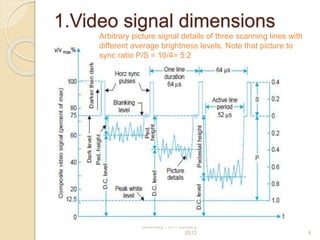
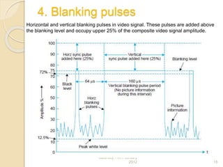
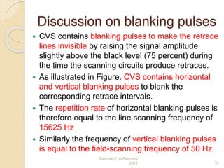
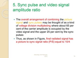
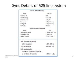
COMPOSITE VIDEO
SIGNAL (CVS)
Television Basics
Saturday,11th February
2012 1
What is CVS?
 Composite video signal consists of a camera signal
corresponding to the desired picture information,
blanking pulses to make the retrace invisible, and
synchronizing pulses to synchronize the transmitter and
receiver scanning.
 A horizontal synchronizing (sync) pulse is needed at the
end of each active line period whereas a vertical sync
pulse is required after each field is scanned.
 The amplitude of both horizontal and vertical sync
pulses is kept the same to obtain higher efficiency of
picture signal transmission but their duration (width) is
chosen to be different for separating them at the
receiver.
 Since sync pulses are needed consecutively and not
simultaneously with the picture signal, these are sent on
a time division basis and thus form a part of the
composite video signal
Saturday,11th February
2012 2
Index
1. Video signal dimensions
2. Horizontal sync details
3. Vertical sync details
4. Scanning sequence details
5. Functions of vertical pulse train
Sync details of 525 line system
Saturday,11th February
2012 3
1.Video signal dimensions
Saturday,11th February
2012 4
Arbitrary picture signal details of three scanning lines with
different average brightness levels. Note that picture to
sync ratio P/S = 10/4= 5:2
Different Terminologies of Video
Signal
 Figure shows 3 different lines for 3
different brightness levels of a scene
 Video signal is constrained to vary
between certain amplitude limits
 Level of the video signal when the
picture detail being transmitted
corresponds to the maximum
whiteness to be handled, is referred to
as peak-white level
 This is fixed at 10 to 12.5 percent of
the maximum value of the signalSaturday,11th February
2012 5
Terminologies continued....
 Black level corresponds to
approximately 72 %
 Sync pulses are added at 75 % level
called the blanking level
 The difference between the black level
and blanking level is known as the
‘Pedestal’. However, in actual practice,
these two levels, being very close,
tend to merge with each other as
shown in the figure
Saturday,11th February
2012 6
Terminologies continued….
 Thus the picture information may vary
between 10 percent to about 75 percent of
the composite video signal depending on the
relative brightness of the picture at any
instant
 Darker the picture the higher will be the
voltage within those limits
 Note that the lowest 10 percent of the voltage
range (whiter than white range) is not used to
minimize noise effects
 This also ensures enough margin for
excessive bright spots to be accommodated
without causing amplitude distortion at the
modulator
Saturday,11th February
2012 7
Terminologies continued….
 At the receiver the picture tube is biased
to ensure that a received video voltage
corresponding to about 10 percent
modulation yields complete whiteness at
that particular point on the screen, and
an analogous arrangement is made for
the black level
 Besides this, the TV receivers are
provided with ‘brightness’ and ‘contrast’
controls to enable the viewer to make
final adjustments as he thinks fit
Saturday,11th February
2012 8
Terminologies continued….
1. D.C. component of the video signal
2. Pedestal height
3. Setting the pedestal level
4. The blanking pulses
5. Sync pulse and video signal
amplitude ratio
Saturday,11th February
2012 9
Saturday,11th February
2012 10
1. D.C. component of the video signal :
 In addition to continuous amplitude
variations for individual picture elements,
the video signal has an average value or
dc component corresponding to the
average brightness of the scene
 In the absence of dc component the
receiver cannot follow changes in
brightness, as the camera signal, say for
grey picture elements on a black
background will then be the same as a
signal for white area on a grey
 dc components of the signal for three lines
have been identified, each representing a
different level of average brightness in the
scene
 It may be noted that the break shown in the
illustration after each line signal is to
emphasize that dc component of the video
signal is the average value for complete
frames rather than lines since the background
information of the picture indicates the
brightness of the scene
 Fig. 3.1 illustrates the concept of change in
the average brightness of the scene with the
help of three lines in separate frames
because the average brightness can changeSaturday,11th February
2012 11
2. Pedestal height: pedestal height is the
distance between the pedestal level and
the average value (dc level) axis of the
video signal
 Indicates average brightness since it
measures how much the average value
differs from the black level
 Even when the signal loses its dc value
when passed through a capacitor-coupled
circuit the distance between the pedestal
and the dc level stays the same and thus
it is convenient to use the pedestal level
as the reference level to indicate average
Saturday,11th February
2012 12
3. Setting the pedestal level: The output signal
from the TV camera is of very small amplitude
and is passed through several stages of ac
coupled high gain amplifiers before being
coupled to a control amplifier.
 Here sync pulses and blanking pulses are
added and then clipped at the correct level to
form the pedestals.
 Since the pedestal height determines the
average brightness of the scene, any smaller
value than the correct one will make the scene
darker while a larger pedestal height will result in
higher average brightness.
 The video control operator who observes the
scene at the studio sets the level for the desired
brightness in the reproduced picture which he is
viewing on a monitor receiver
Saturday,11th February
2012 13
 This is known as dc insertion because this
amounts to adding a dc component to the ac
signal.
 Once the dc insertion has been
accomplished the pedestal level becomes
the black reference and the pedestal height
indicates correct relative brightness for the
reproduced picture.
 However, the dc level inserted in the control
amplifier is usually lost in succeeding stages
because of capacitive coupling, but still the
correct dc component can be reinserted
when necessary because the pedestal height
remains the same.Saturday,11th February
2012 14
4. Blanking pulses
Saturday,11th February
2012 15
Horizontal and vertical blanking pulses in video signal. These pulses are added above
the blanking level and occupy upper 25% of the composite video signal amplitude.
Discussion on blanking pulses
 CVS contains blanking pulses to make the retrace
lines invisible by raising the signal amplitude
slightly above the black level (75 percent) during
the time the scanning circuits produce retraces.
 As illustrated in Figure, CVS contains horizontal
and vertical blanking pulses to blank the
corresponding retrace intervals.
 The repetition rate of horizontal blanking pulses is
therefore equal to the line scanning frequency of
15625 Hz
 Similarly the frequency of vertical blanking pulses
is equal to the field-scanning frequency of 50 Hz.
Saturday,11th February
2012 16
Discussion on blanking pulses,
continued..
 It may be noted that though the level of the
blanking pulses is distinctly above the picture
signal information, these are not used as sync
pulses
 The reason is that any occasional signal
corresponding to any extreme black portion in the
picture may rise above the blanking level and might
conceivably interfere with the synchronization of
the scanning generators.
 Therefore, the sync pulses, specially designed for
triggering the sweep oscillators are placed in the
upper 25 per cent (75 per cent to 100 per cent of
the carrier amplitude) of the video signal, and are
transmitted along with the picture signal.
Saturday,11th February
2012 17
5. Sync pulse and video signal
amplitude ratio
 The overall arrangement of combining the picture
signal and sync pulses may be thought of as a kind
of voltage division multiplexing where about 65 per
cent of the carrier amplitude is occupied by the
video signal and the upper 25 per cent by the sync
pulses
 Thus, as shown in Figure, final radiated signal has
a picture to sync signal ratio (P/S) equal to 10/4
Saturday,11th February
2012 18
Sync and video signal ratio
continues….
 5:2 is apt because. if picture signal amplitude is
increased at the expense of sync pulses, then
when the signal to noise ratio of the received signal
falls, a point is reached when the sync pulse
amplitude becomes insufficient to keep the picture
locked even though the picture voltage is still of
adequate amplitude to yield an acceptable picture
 On the other hand if sync pulse height is increased
at the expense of the picture detail, then under
similar conditions the raster remains locked but the
picture content is of too low an amplitude to set up
a worthwhile picture
Saturday,11th February
2012 19
Sync and video signal ratio
continues….
 A ratio of P/S = 10/4 results in a
situation such that when the signal to
noise ratio reaches a certain low level,
the sync amplitude becomes
insufficient, i.e., the sync fails at the
same time as the picture ceases to be
of entertainment value.
 This represents the most efficient use
of the television system.
Saturday,11th February
2012 20
HORIZONTAL SYNC
DETAILS
CVS
Saturday,11th February
2012 21
Saturday,11th February
2012 22
Horizontal line and sync details compared to horizontal deflection
saw tooth and picture space on the raster
Horizontal Sync Details
 The horizontal blanking period and sync pulse
details are illustrated in Figure
 Interval between two consecutive horizontal
scanning lines is indicated by H
 Out of a total line period of 64 μs, the line blanking
period is 12 μs
 During this interval a line synchronizing pulse is
inserted
 The pulses corresponding to the differentiated
leading edges of the sync pulses are actually used
to synchronize the horizontal scanning oscillator
Saturday,11th February
2012 23
 The line blanking period is divided into
3: -‘front porch’, 1.5 µs
- ‘line sync’ pulse 4.7 µs
- and the ‘back porch’ 5.8 µs
Saturday,11th February
2012 24
1. Front porch
 Brief cushioning period of 1.5 μs
inserted
 This interval allows the receiver video
circuit to settle down from whatever
picture voltage level exists at the end
of the picture line to the blanking level
before the sync pulse occurs
 Thus sync circuits at the receiver are
isolated from the influence of end of
the line picture detailsSaturday,11th February
2012 25
Pulling-on-whites
 The most stringent demand is made on the video
circuits when peak white detail occurs at the end of
a line
 Despite the existence of the front porch when the
line ends in an extreme white detail, and the signal
amplitude touches almost zero level, the video
voltage level fails to decay to the blanking level
before the leading-edge of the line sync pulse
occurs
 This results in late triggering of the time base circuit
thus upsetting the ‘horz’ line sync circuit
 As a result the spot (beam) is late in arriving at the
left of the screen and picture information on the
next line is displaced to the left. This effect isSaturday,11th February
2012 26
2. Line Sync Pulse
 After the front porch of blanking,
horizontal retrace is produced when
the sync pulse starts
 The flyback is definitely blanked out
because the sync level is blacker than
black
 Line sync pulses are separated at the
receiver and utilized to keep the
receiver line time base in precise
synchronism with the distantSaturday,11th February
2012 27
Line Sync Pulse
 The nominal time duration for the line
sync pulses is 4.7 μs
 During this period the beam on the
raster almost completes its back
stroke (retrace) and arrives at the
extreme left end of the raster
Saturday,11th February
2012 28
3.Back Porch
 This period of 5.8 μs at the blanking
level allows plenty of time for line
flyback to be completed
 It also permits time for the horizontal
time-base circuit to reverse direction
of current for the initiation of the
scanning of next line
 the relative timings are so set that
small black bars are formed at both
the ends of the raster in the horizontal
plane Saturday,11th February
2012 29
 These blanked bars at the sides have no
effect on the picture details reproduced
during the active line period.
 Back porch also provides the necessary
amplitude equal to the blanking level
(reference level) and enables to preserve
the dc content of the picture information at
the transmitter
 At the receiver this level which is
independent of the picture details is utilized
in
 the AGC (automatic gain control) circuits to
develop true AGC voltage proportional toSaturday,11th February
2012 30
VERTICAL SYNC
DETAILS
CVS
Saturday,11th February
2012 31
Vertical Sync
 vertical sync pulse train added after
each field, at the end of both even add
odd fields
 it has to meet several exacting
requirements
 Its width has to be kept much larger
than the horizontal sync pulse, in order
to derive a suitable field sync pulse at
the receiver to trigger the field sweep
oscillator
 standards specify that the vertical syncSaturday,11th February
2012 32
 If the width is less than this, it becomes
difficult to distinguish between horizontal
and vertical pulses at the receiver
 If the width is greater than this, the
transmitter must operate at peak power
for an unnecessarily long interval of time
 In the 625 line system 2.5 line period
(2.5 × 64 = 160 μs) has been allotted for
the vertical sync pulses
 a vertical sync pulse commences at the
end of 1st half of 313th line (end of first
field) and terminates at the end of 315th
line Saturday,11th February
2012 33
Saturday,11th February
2012
34
• Similarly after an exact interval of 20 ms (one
field period) the next sync pulse occupies line
numbers—1st, 2nd and 1st half of third, just after
the second field is over
• the beginning of these pulses has been aligned in
the figure to signify that these must occur after
the end of vertical stroke of the beam in each
field, i.e., after each 1/50th of a second
• This alignment of vertical sync pulses, one at the
end of a half-line period and the other after a full
line period results in a relative misalignment of
the horizontal sync pulses and they do not appear
one above the other but occur at half-line
intervals with respect to each other
Tuesday, February 14, 2012 35
• horizontal sync pulses continue to occur
exactly at 64 μs intervals (except during the
vertical sync pulse periods) throughout the
scanning period from frame to frame and the
apparent shift of 32 μs is only due to the
alignment of vertical sync instances in the
figure
• the horizontal sync information is extracted
from the sync pulse train by differentiation,
i.e., by passing the pulse train through a high-
pass filter
Saturday,11th February
2012
36
• Indeed pulses corresponding to the
differentiated leading edges of sync pulses are
used to synchronize the horizontal scanning
oscillator
• The process of deriving these pulses is
illustrated in Fig. 3.5.
• receivers often use monostable multivibrators
to generate horizontal scan, and so a pulse is
required to initiate each and every cycle of the
horizontal oscillator in the receiver
Saturday,11th February
2012
37
Deriving the sync pulses
Saturday,11th February
2012
38
• 1.Drawback: horizontal sync pulses are
available both during the active and blanked
line periods but there are no sync pulses
(leading edges) available during the 2.5 line
vertical sync period
• Thus the horizontal sweep oscillator that
operates at 15625 Hz, would tend to step out
of synchronism during each vertical sync
period
• The situation after an odd field is even worse
• Vertical blanking period at the end of an odd
field begins midway through a horizontal line
Saturday,11th February
2012
39
• leading edge of the vertical sync pulse comes
at the wrong time to provide synchronization
for the horizontal oscillator
• Therefore, it becomes necessary to cut slots in
the vertical sync pulse at half-line-intervals to
provide horizontal sync pulses at the correct
instances both after even and odd fields
• The technique is to take the video signal
amplitude back to the blanking level 4.7 μs
before the line pulses are needed
Saturday,11th February
2012
40
• The waveform is then returned to the maximum
level at the moment the line sweep circuit needs
synchronization
• Thus five narrow slots of 4.7 μs width get formed
in each vertical sync pulse at intervals of 32 μs
• Rising edges of these pulses are actually used to
trigger the horizontal oscillator
• Resulting waveforms together with line numbers
and the differentiated output of both the field
trains is illustrated in Next Slide Fig
• This insertion of short pulses is known as
notching or serration of the broad field pulses
Saturday,11th February
2012
41
Saturday,11th February
2012
42
• though the vertical pulse has been broken to
yield horizontal sync pulses, the effect on the
vertical pulse is substantially unchanged
• It still remains above the blanking voltage level all
of the time it is acting
• pulse width is still much wider than the horizontal
pulse width and thus can be easily separated at
the receiver
• From fig., each horizontal sync pulse yields a
positive spiked output from its leading edge and a
negative spiked pulse from its trailing edge
• negative-going triggering pulses may be removed
with a diode since only the positive going pulses
are effective in locking the horizontal oscillator
Saturday,11th February
2012
43
• Note that during the intervals of serrated
vertical pulse trains, alternate vertical spikes
are utilized ( each serrated pulse 32 μs and
horizontal line period is 64 μs, so alternate
vertical spikes used )
• pulses not used in one field are the ones
utilized during the second field
• This happens because of the half-line
difference at the commencement of each field
• and the fact that notched vertical sync pulses
occur at intervals of 32 μs and not 64 μs as
required by the horizontal sweep oscillator
Saturday,11th February
2012
44
• The pulses that come at a time when they
cannot trigger the oscillator are ignored
• Thus the requirement of keeping the
horizontal sweep circuit locked despite
insertion of vertical sync pulses is realized
Saturday,11th February
2012
45
• 2. Drawback : synchronization of the vertical
sweep oscillator in the receiver is obtained
from vertical sync pulses by integration
• the time-constant R2C2 is chosen to be large
compared to the duration of horizontal pulses
but not with respect to width of the vertical
sync pulses
• The voltage builds up because the capacitor
has more time to charge, 27.3 μs and only 4.7
μs to discharge
Saturday,11th February
2012
46
• Situation is not the same for the beginning of the 2nd
(even) field.
• Here the last horizontal pulse corresponding to the
beginning of 313th line is separated from the first
vertical pulse by only half-a-line.
• The voltage developed across the vertical filter will
thus not have enough time to reach zero before the
arrival of the first vertical pulse, which means that the
voltage build-up does not start from zero, as in the case
of the 1st field.
• The residual voltage on account of the half line
discrepancy gets added to the voltage developed on
account of the broad vertical pulses and thus the
voltage developed across the output filter is some
what higher at each instant as compared to the voltage
developed at the beginning of the first-field. This is
shown in dotted chain line
Saturday,11th February
2012
47
Saturday,11th February
2012
48
Concept of Equalizing Pulses
• To take care of this drawback which occurs on
account of the half line discrepancy five
narrow pulses are added on either side of the
vertical sync pulses. These are known as pre-
equalizing and post-equalizing pulses.
• Each set consists of five narrow pulses
occupying 2.5 lines period on either side of
the vertical sync pulses
Saturday,11th February
2012
49
Pre-equalizing and post equalizing
pulse details with line numbers occupied by them in each field
are given
Saturday,11th February
2012
50
Effect of equalizing pulses
• The effect of these pulses is to shift the half-
line discrepancy away both from the
beginning and end of vertical sync pulses
• Pre-equalizing pulses being of 2.3 μs duration
result in the discharge of the capacitor to
essentially zero voltage in both the fields,
despite the half-line discrepancy before the
voltage build-up starts with the arrival of
vertical sync pulses
Saturday,11th February
2012
51
Effect of equalizing pulses
Saturday,11th February
2012
52
Scanning Sequence Details
Saturday,11th February
2012
53
Saturday,11th February
2012
54
FUNCTIONS OF VERTICAL PULSE
TRAIN
• By serrating the vertical sync pulses and the providing pre- and
post-equalizing pulses the following basic requirements necessary
for successful interlaced scanning are ensured
• (a) A suitable field sync pulse is derived for triggering the field
oscillator.
• (b) The line oscillator continues to receive triggering pulses at
correct intervals while the process of initiation and completion of
the field time-base stroke is going on.
• (c) It becomes possible to insert vertical sync pulses at the end of a
line after the 2nd field and at the middle of a line at the end of the
1st field without causing any interlace error.
• (d) The vertical sync build up at the receiver has precisely the same
shape and timing on odd and even fields
Saturday,11th February
2012
55
Saturday,11th February
2012
56
Sync Details of 525 line system
Saturday,11th February
2012
57

composite video signal

  • 1.
    COMPOSITE VIDEO SIGNAL (CVS) TelevisionBasics Saturday,11th February 2012 1
  • 2.
    What is CVS? Composite video signal consists of a camera signal corresponding to the desired picture information, blanking pulses to make the retrace invisible, and synchronizing pulses to synchronize the transmitter and receiver scanning.  A horizontal synchronizing (sync) pulse is needed at the end of each active line period whereas a vertical sync pulse is required after each field is scanned.  The amplitude of both horizontal and vertical sync pulses is kept the same to obtain higher efficiency of picture signal transmission but their duration (width) is chosen to be different for separating them at the receiver.  Since sync pulses are needed consecutively and not simultaneously with the picture signal, these are sent on a time division basis and thus form a part of the composite video signal Saturday,11th February 2012 2
  • 3.
    Index 1. Video signaldimensions 2. Horizontal sync details 3. Vertical sync details 4. Scanning sequence details 5. Functions of vertical pulse train Sync details of 525 line system Saturday,11th February 2012 3
  • 4.
    1.Video signal dimensions Saturday,11thFebruary 2012 4 Arbitrary picture signal details of three scanning lines with different average brightness levels. Note that picture to sync ratio P/S = 10/4= 5:2
  • 5.
    Different Terminologies ofVideo Signal  Figure shows 3 different lines for 3 different brightness levels of a scene  Video signal is constrained to vary between certain amplitude limits  Level of the video signal when the picture detail being transmitted corresponds to the maximum whiteness to be handled, is referred to as peak-white level  This is fixed at 10 to 12.5 percent of the maximum value of the signalSaturday,11th February 2012 5
  • 6.
    Terminologies continued....  Blacklevel corresponds to approximately 72 %  Sync pulses are added at 75 % level called the blanking level  The difference between the black level and blanking level is known as the ‘Pedestal’. However, in actual practice, these two levels, being very close, tend to merge with each other as shown in the figure Saturday,11th February 2012 6
  • 7.
    Terminologies continued….  Thusthe picture information may vary between 10 percent to about 75 percent of the composite video signal depending on the relative brightness of the picture at any instant  Darker the picture the higher will be the voltage within those limits  Note that the lowest 10 percent of the voltage range (whiter than white range) is not used to minimize noise effects  This also ensures enough margin for excessive bright spots to be accommodated without causing amplitude distortion at the modulator Saturday,11th February 2012 7
  • 8.
    Terminologies continued….  Atthe receiver the picture tube is biased to ensure that a received video voltage corresponding to about 10 percent modulation yields complete whiteness at that particular point on the screen, and an analogous arrangement is made for the black level  Besides this, the TV receivers are provided with ‘brightness’ and ‘contrast’ controls to enable the viewer to make final adjustments as he thinks fit Saturday,11th February 2012 8
  • 9.
    Terminologies continued…. 1. D.C.component of the video signal 2. Pedestal height 3. Setting the pedestal level 4. The blanking pulses 5. Sync pulse and video signal amplitude ratio Saturday,11th February 2012 9
  • 10.
    Saturday,11th February 2012 10 1.D.C. component of the video signal :  In addition to continuous amplitude variations for individual picture elements, the video signal has an average value or dc component corresponding to the average brightness of the scene  In the absence of dc component the receiver cannot follow changes in brightness, as the camera signal, say for grey picture elements on a black background will then be the same as a signal for white area on a grey
  • 11.
     dc componentsof the signal for three lines have been identified, each representing a different level of average brightness in the scene  It may be noted that the break shown in the illustration after each line signal is to emphasize that dc component of the video signal is the average value for complete frames rather than lines since the background information of the picture indicates the brightness of the scene  Fig. 3.1 illustrates the concept of change in the average brightness of the scene with the help of three lines in separate frames because the average brightness can changeSaturday,11th February 2012 11
  • 12.
    2. Pedestal height:pedestal height is the distance between the pedestal level and the average value (dc level) axis of the video signal  Indicates average brightness since it measures how much the average value differs from the black level  Even when the signal loses its dc value when passed through a capacitor-coupled circuit the distance between the pedestal and the dc level stays the same and thus it is convenient to use the pedestal level as the reference level to indicate average Saturday,11th February 2012 12
  • 13.
    3. Setting thepedestal level: The output signal from the TV camera is of very small amplitude and is passed through several stages of ac coupled high gain amplifiers before being coupled to a control amplifier.  Here sync pulses and blanking pulses are added and then clipped at the correct level to form the pedestals.  Since the pedestal height determines the average brightness of the scene, any smaller value than the correct one will make the scene darker while a larger pedestal height will result in higher average brightness.  The video control operator who observes the scene at the studio sets the level for the desired brightness in the reproduced picture which he is viewing on a monitor receiver Saturday,11th February 2012 13
  • 14.
     This isknown as dc insertion because this amounts to adding a dc component to the ac signal.  Once the dc insertion has been accomplished the pedestal level becomes the black reference and the pedestal height indicates correct relative brightness for the reproduced picture.  However, the dc level inserted in the control amplifier is usually lost in succeeding stages because of capacitive coupling, but still the correct dc component can be reinserted when necessary because the pedestal height remains the same.Saturday,11th February 2012 14
  • 15.
    4. Blanking pulses Saturday,11thFebruary 2012 15 Horizontal and vertical blanking pulses in video signal. These pulses are added above the blanking level and occupy upper 25% of the composite video signal amplitude.
  • 16.
    Discussion on blankingpulses  CVS contains blanking pulses to make the retrace lines invisible by raising the signal amplitude slightly above the black level (75 percent) during the time the scanning circuits produce retraces.  As illustrated in Figure, CVS contains horizontal and vertical blanking pulses to blank the corresponding retrace intervals.  The repetition rate of horizontal blanking pulses is therefore equal to the line scanning frequency of 15625 Hz  Similarly the frequency of vertical blanking pulses is equal to the field-scanning frequency of 50 Hz. Saturday,11th February 2012 16
  • 17.
    Discussion on blankingpulses, continued..  It may be noted that though the level of the blanking pulses is distinctly above the picture signal information, these are not used as sync pulses  The reason is that any occasional signal corresponding to any extreme black portion in the picture may rise above the blanking level and might conceivably interfere with the synchronization of the scanning generators.  Therefore, the sync pulses, specially designed for triggering the sweep oscillators are placed in the upper 25 per cent (75 per cent to 100 per cent of the carrier amplitude) of the video signal, and are transmitted along with the picture signal. Saturday,11th February 2012 17
  • 18.
    5. Sync pulseand video signal amplitude ratio  The overall arrangement of combining the picture signal and sync pulses may be thought of as a kind of voltage division multiplexing where about 65 per cent of the carrier amplitude is occupied by the video signal and the upper 25 per cent by the sync pulses  Thus, as shown in Figure, final radiated signal has a picture to sync signal ratio (P/S) equal to 10/4 Saturday,11th February 2012 18
  • 19.
    Sync and videosignal ratio continues….  5:2 is apt because. if picture signal amplitude is increased at the expense of sync pulses, then when the signal to noise ratio of the received signal falls, a point is reached when the sync pulse amplitude becomes insufficient to keep the picture locked even though the picture voltage is still of adequate amplitude to yield an acceptable picture  On the other hand if sync pulse height is increased at the expense of the picture detail, then under similar conditions the raster remains locked but the picture content is of too low an amplitude to set up a worthwhile picture Saturday,11th February 2012 19
  • 20.
    Sync and videosignal ratio continues….  A ratio of P/S = 10/4 results in a situation such that when the signal to noise ratio reaches a certain low level, the sync amplitude becomes insufficient, i.e., the sync fails at the same time as the picture ceases to be of entertainment value.  This represents the most efficient use of the television system. Saturday,11th February 2012 20
  • 21.
  • 22.
    Saturday,11th February 2012 22 Horizontalline and sync details compared to horizontal deflection saw tooth and picture space on the raster
  • 23.
    Horizontal Sync Details The horizontal blanking period and sync pulse details are illustrated in Figure  Interval between two consecutive horizontal scanning lines is indicated by H  Out of a total line period of 64 μs, the line blanking period is 12 μs  During this interval a line synchronizing pulse is inserted  The pulses corresponding to the differentiated leading edges of the sync pulses are actually used to synchronize the horizontal scanning oscillator Saturday,11th February 2012 23
  • 24.
     The lineblanking period is divided into 3: -‘front porch’, 1.5 µs - ‘line sync’ pulse 4.7 µs - and the ‘back porch’ 5.8 µs Saturday,11th February 2012 24
  • 25.
    1. Front porch Brief cushioning period of 1.5 μs inserted  This interval allows the receiver video circuit to settle down from whatever picture voltage level exists at the end of the picture line to the blanking level before the sync pulse occurs  Thus sync circuits at the receiver are isolated from the influence of end of the line picture detailsSaturday,11th February 2012 25
  • 26.
    Pulling-on-whites  The moststringent demand is made on the video circuits when peak white detail occurs at the end of a line  Despite the existence of the front porch when the line ends in an extreme white detail, and the signal amplitude touches almost zero level, the video voltage level fails to decay to the blanking level before the leading-edge of the line sync pulse occurs  This results in late triggering of the time base circuit thus upsetting the ‘horz’ line sync circuit  As a result the spot (beam) is late in arriving at the left of the screen and picture information on the next line is displaced to the left. This effect isSaturday,11th February 2012 26
  • 27.
    2. Line SyncPulse  After the front porch of blanking, horizontal retrace is produced when the sync pulse starts  The flyback is definitely blanked out because the sync level is blacker than black  Line sync pulses are separated at the receiver and utilized to keep the receiver line time base in precise synchronism with the distantSaturday,11th February 2012 27
  • 28.
    Line Sync Pulse The nominal time duration for the line sync pulses is 4.7 μs  During this period the beam on the raster almost completes its back stroke (retrace) and arrives at the extreme left end of the raster Saturday,11th February 2012 28
  • 29.
    3.Back Porch  Thisperiod of 5.8 μs at the blanking level allows plenty of time for line flyback to be completed  It also permits time for the horizontal time-base circuit to reverse direction of current for the initiation of the scanning of next line  the relative timings are so set that small black bars are formed at both the ends of the raster in the horizontal plane Saturday,11th February 2012 29
  • 30.
     These blankedbars at the sides have no effect on the picture details reproduced during the active line period.  Back porch also provides the necessary amplitude equal to the blanking level (reference level) and enables to preserve the dc content of the picture information at the transmitter  At the receiver this level which is independent of the picture details is utilized in  the AGC (automatic gain control) circuits to develop true AGC voltage proportional toSaturday,11th February 2012 30
  • 31.
  • 32.
    Vertical Sync  verticalsync pulse train added after each field, at the end of both even add odd fields  it has to meet several exacting requirements  Its width has to be kept much larger than the horizontal sync pulse, in order to derive a suitable field sync pulse at the receiver to trigger the field sweep oscillator  standards specify that the vertical syncSaturday,11th February 2012 32
  • 33.
     If thewidth is less than this, it becomes difficult to distinguish between horizontal and vertical pulses at the receiver  If the width is greater than this, the transmitter must operate at peak power for an unnecessarily long interval of time  In the 625 line system 2.5 line period (2.5 × 64 = 160 μs) has been allotted for the vertical sync pulses  a vertical sync pulse commences at the end of 1st half of 313th line (end of first field) and terminates at the end of 315th line Saturday,11th February 2012 33
  • 34.
  • 35.
    • Similarly afteran exact interval of 20 ms (one field period) the next sync pulse occupies line numbers—1st, 2nd and 1st half of third, just after the second field is over • the beginning of these pulses has been aligned in the figure to signify that these must occur after the end of vertical stroke of the beam in each field, i.e., after each 1/50th of a second • This alignment of vertical sync pulses, one at the end of a half-line period and the other after a full line period results in a relative misalignment of the horizontal sync pulses and they do not appear one above the other but occur at half-line intervals with respect to each other Tuesday, February 14, 2012 35
  • 36.
    • horizontal syncpulses continue to occur exactly at 64 μs intervals (except during the vertical sync pulse periods) throughout the scanning period from frame to frame and the apparent shift of 32 μs is only due to the alignment of vertical sync instances in the figure • the horizontal sync information is extracted from the sync pulse train by differentiation, i.e., by passing the pulse train through a high- pass filter Saturday,11th February 2012 36
  • 37.
    • Indeed pulsescorresponding to the differentiated leading edges of sync pulses are used to synchronize the horizontal scanning oscillator • The process of deriving these pulses is illustrated in Fig. 3.5. • receivers often use monostable multivibrators to generate horizontal scan, and so a pulse is required to initiate each and every cycle of the horizontal oscillator in the receiver Saturday,11th February 2012 37
  • 38.
    Deriving the syncpulses Saturday,11th February 2012 38
  • 39.
    • 1.Drawback: horizontalsync pulses are available both during the active and blanked line periods but there are no sync pulses (leading edges) available during the 2.5 line vertical sync period • Thus the horizontal sweep oscillator that operates at 15625 Hz, would tend to step out of synchronism during each vertical sync period • The situation after an odd field is even worse • Vertical blanking period at the end of an odd field begins midway through a horizontal line Saturday,11th February 2012 39
  • 40.
    • leading edgeof the vertical sync pulse comes at the wrong time to provide synchronization for the horizontal oscillator • Therefore, it becomes necessary to cut slots in the vertical sync pulse at half-line-intervals to provide horizontal sync pulses at the correct instances both after even and odd fields • The technique is to take the video signal amplitude back to the blanking level 4.7 μs before the line pulses are needed Saturday,11th February 2012 40
  • 41.
    • The waveformis then returned to the maximum level at the moment the line sweep circuit needs synchronization • Thus five narrow slots of 4.7 μs width get formed in each vertical sync pulse at intervals of 32 μs • Rising edges of these pulses are actually used to trigger the horizontal oscillator • Resulting waveforms together with line numbers and the differentiated output of both the field trains is illustrated in Next Slide Fig • This insertion of short pulses is known as notching or serration of the broad field pulses Saturday,11th February 2012 41
  • 42.
  • 43.
    • though thevertical pulse has been broken to yield horizontal sync pulses, the effect on the vertical pulse is substantially unchanged • It still remains above the blanking voltage level all of the time it is acting • pulse width is still much wider than the horizontal pulse width and thus can be easily separated at the receiver • From fig., each horizontal sync pulse yields a positive spiked output from its leading edge and a negative spiked pulse from its trailing edge • negative-going triggering pulses may be removed with a diode since only the positive going pulses are effective in locking the horizontal oscillator Saturday,11th February 2012 43
  • 44.
    • Note thatduring the intervals of serrated vertical pulse trains, alternate vertical spikes are utilized ( each serrated pulse 32 μs and horizontal line period is 64 μs, so alternate vertical spikes used ) • pulses not used in one field are the ones utilized during the second field • This happens because of the half-line difference at the commencement of each field • and the fact that notched vertical sync pulses occur at intervals of 32 μs and not 64 μs as required by the horizontal sweep oscillator Saturday,11th February 2012 44
  • 45.
    • The pulsesthat come at a time when they cannot trigger the oscillator are ignored • Thus the requirement of keeping the horizontal sweep circuit locked despite insertion of vertical sync pulses is realized Saturday,11th February 2012 45
  • 46.
    • 2. Drawback: synchronization of the vertical sweep oscillator in the receiver is obtained from vertical sync pulses by integration • the time-constant R2C2 is chosen to be large compared to the duration of horizontal pulses but not with respect to width of the vertical sync pulses • The voltage builds up because the capacitor has more time to charge, 27.3 μs and only 4.7 μs to discharge Saturday,11th February 2012 46
  • 47.
    • Situation isnot the same for the beginning of the 2nd (even) field. • Here the last horizontal pulse corresponding to the beginning of 313th line is separated from the first vertical pulse by only half-a-line. • The voltage developed across the vertical filter will thus not have enough time to reach zero before the arrival of the first vertical pulse, which means that the voltage build-up does not start from zero, as in the case of the 1st field. • The residual voltage on account of the half line discrepancy gets added to the voltage developed on account of the broad vertical pulses and thus the voltage developed across the output filter is some what higher at each instant as compared to the voltage developed at the beginning of the first-field. This is shown in dotted chain line Saturday,11th February 2012 47
  • 48.
  • 49.
    Concept of EqualizingPulses • To take care of this drawback which occurs on account of the half line discrepancy five narrow pulses are added on either side of the vertical sync pulses. These are known as pre- equalizing and post-equalizing pulses. • Each set consists of five narrow pulses occupying 2.5 lines period on either side of the vertical sync pulses Saturday,11th February 2012 49
  • 50.
    Pre-equalizing and postequalizing pulse details with line numbers occupied by them in each field are given Saturday,11th February 2012 50
  • 51.
    Effect of equalizingpulses • The effect of these pulses is to shift the half- line discrepancy away both from the beginning and end of vertical sync pulses • Pre-equalizing pulses being of 2.3 μs duration result in the discharge of the capacitor to essentially zero voltage in both the fields, despite the half-line discrepancy before the voltage build-up starts with the arrival of vertical sync pulses Saturday,11th February 2012 51
  • 52.
    Effect of equalizingpulses Saturday,11th February 2012 52
  • 53.
  • 54.
  • 55.
    FUNCTIONS OF VERTICALPULSE TRAIN • By serrating the vertical sync pulses and the providing pre- and post-equalizing pulses the following basic requirements necessary for successful interlaced scanning are ensured • (a) A suitable field sync pulse is derived for triggering the field oscillator. • (b) The line oscillator continues to receive triggering pulses at correct intervals while the process of initiation and completion of the field time-base stroke is going on. • (c) It becomes possible to insert vertical sync pulses at the end of a line after the 2nd field and at the middle of a line at the end of the 1st field without causing any interlace error. • (d) The vertical sync build up at the receiver has precisely the same shape and timing on odd and even fields Saturday,11th February 2012 55
  • 56.
  • 57.
    Sync Details of525 line system Saturday,11th February 2012 57