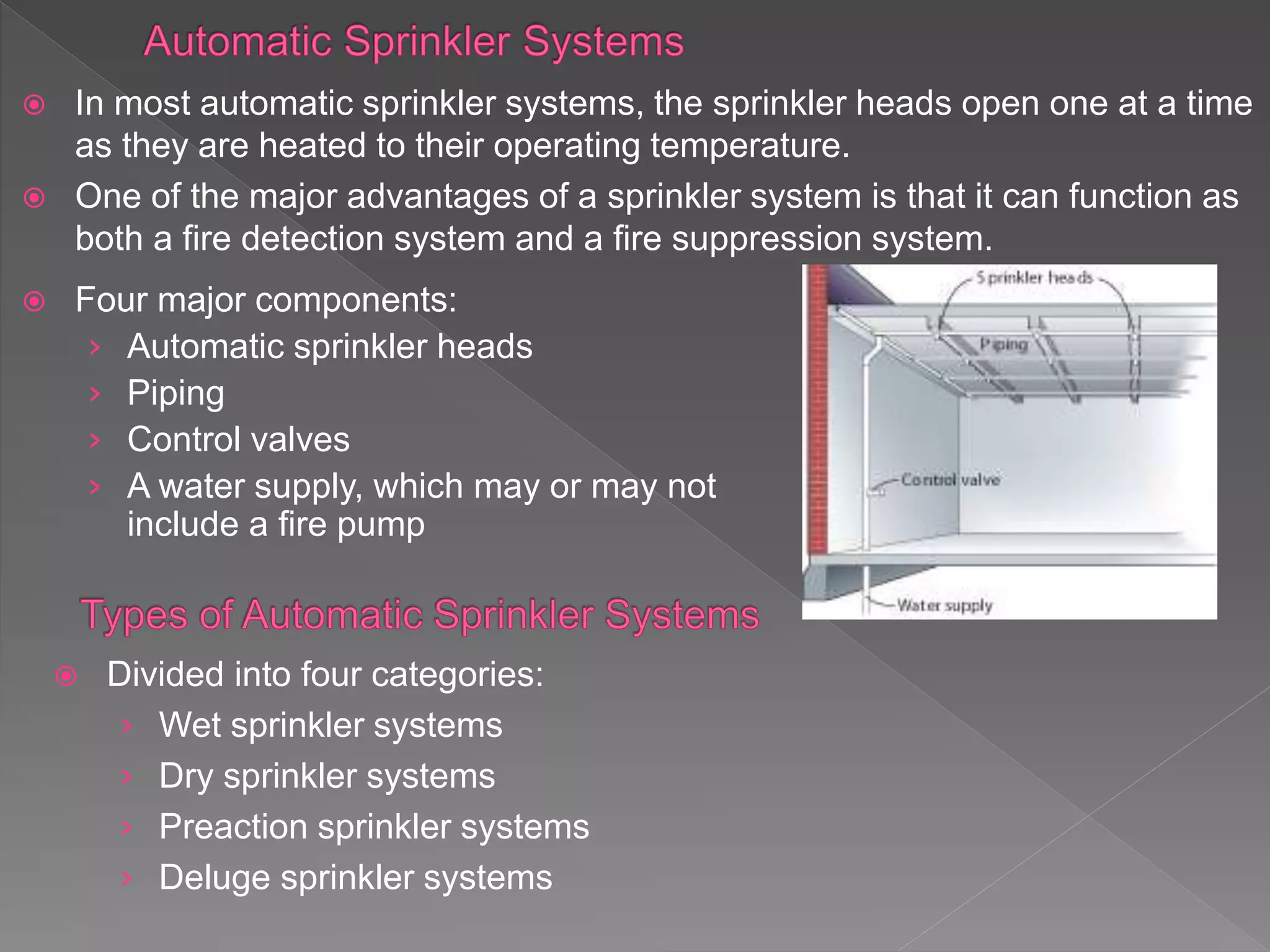
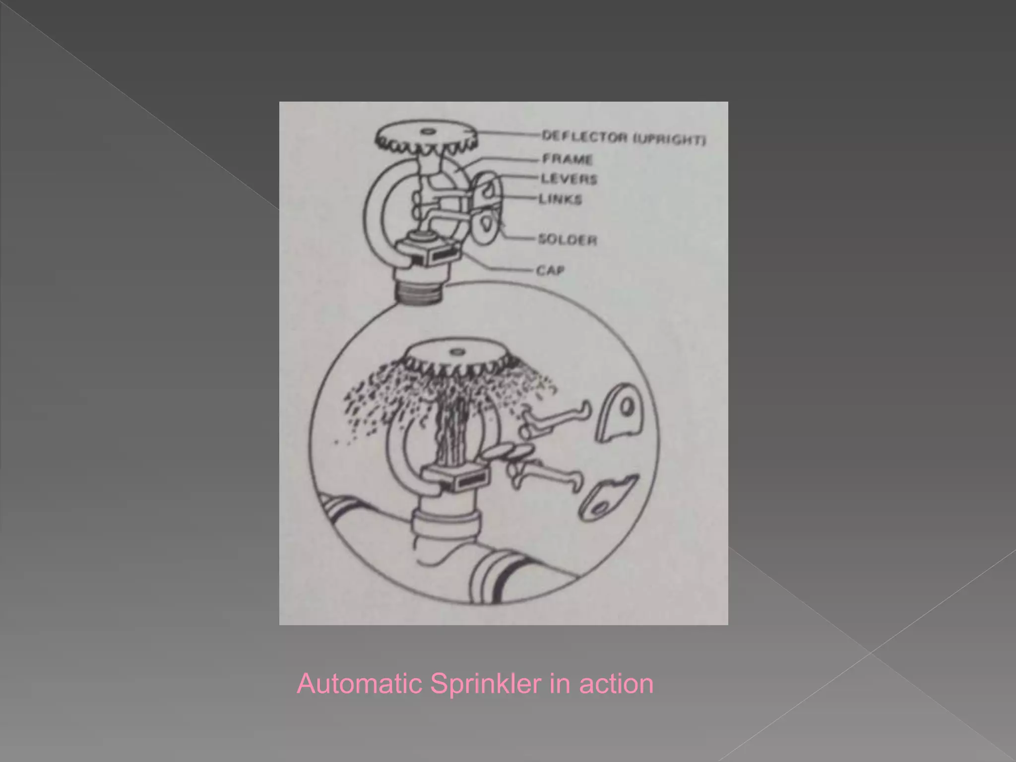
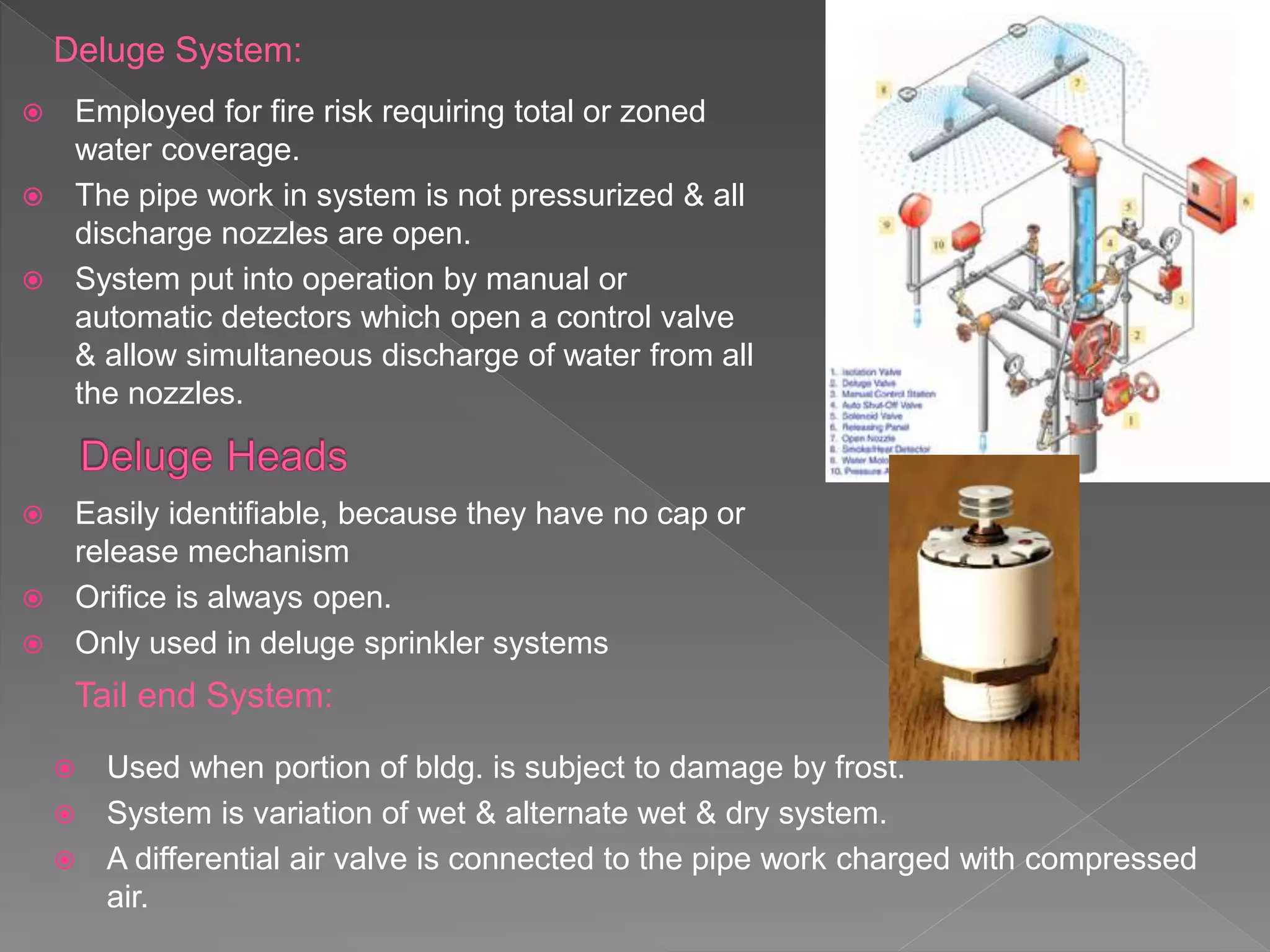
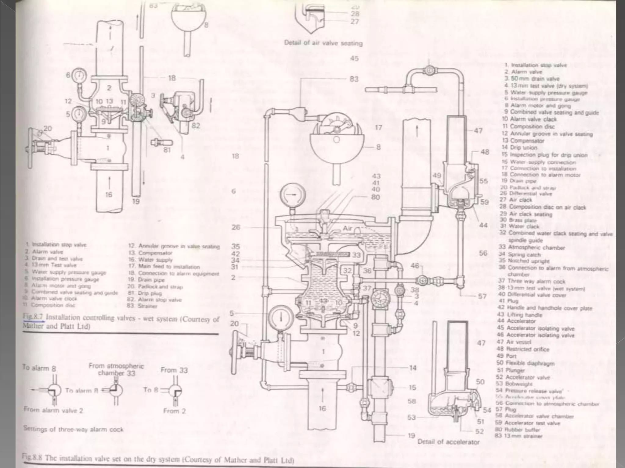
FIRE SAFETY & PROTECTION IN
BUILDINGS
SPRINKLER SYSTEMS
https://yourarchischool.blogspot.com
FOR MORE LOG ON TO
 In most automatic sprinkler systems, the sprinkler heads open one at a time
as they are heated to their operating temperature.
 One of the major advantages of a sprinkler system is that it can function as
both a fire detection system and a fire suppression system.
 Four major components:
› Automatic sprinkler heads
› Piping
› Control valves
› A water supply, which may or may not
include a fire pump
 Divided into four categories:
› Wet sprinkler systems
› Dry sprinkler systems
› Preaction sprinkler systems
› Deluge sprinkler systems
WET RISERS
o Bldgs. Exceeding 20 storeys in ht. above G.L
o Riser always charged with water under pressure fed
by pumping sets from a break tanks.
o Hydrants connected to riser on each floor & pumps
capable of providing pressure of 410 kPa at highest
hydrant.
o To protect hose pipe connected to riser, hydrant s of
lower flr. Should incorporate orifice plate.
o 75mm dia return pipe connected from the hydrants
back to supply source & static water pressure with
flow of water not to exceed 690 kPa in pipe work.
o No. of wet risers, positions to be fitted, outlets fitted, details of const. mats. Used
conform to same specificationof that of wet risers.
o Pumps to provide adequate supply of water to each riser at all times, duplicate
pumps to be provided, one of which is stand by purposes.
o Each capable of delivering min. flow rate of 15lt/s, connected in parallel, with their
suctions permanently wet when tank is filled.
o Pressure switch fitted in pipeline on delivery side of pumps.
o
DRY RISERS
o charged with water by the fire brigade,
connecting the suction side of pumps to water
main via underground fire hydrant.
o The fire brigade connect the suction side of
their pumps to water main via underground F
hrdrants.
o Outlet side of pumps connected to the dry
riser inlet at G.L & pumps force water from
main into riser.
o automatic air valve at top of riser opens to
allow air in the pipe to escape, closes when
the pipe is full of water. Fireman can connect
their hose reels to landing valves fitted to the
riser.
o It is merely an extension of fireman’s hose & can only be installed when prompt
attention can be relied upon from local fire brigade.
o Should be sited inside ventilated lobby, staircase, or in an staircase enclosure.
o In bldgs. Which do not exceed 45m in height , where only 64mm dia landing valve is
provided, internal dia of riser should be 100mm.
o Bldgs. 45-60m ht. & less than 45m in which two 64mm dia landing valves are
provided on each floor from the riser, int. dia should be 150mm.
 Most important & successful of FF systems.
 Rebate of 70% on fire premium, which offsets cost of
const.
 First aid system for dealing with fire.
 Shall cover whole of bldg. Most common and the
least expensive type of automatic sprinkler system
 Piping always filled with water.
 As sprinkler head activates, water is immediately
discharged onto the fire. Major drawback: cannot be
used in areas where temperatures drop below
freezing Will also flow water if a sprinkler head is
accidentally opened or a leak occurs in the piping.
 Wet System:
used in bldgs. With temp. above 0*C
with no risk of water freezing in pipes,
constantly filled with water, water flow
activates hydraulically operated
operated alarm bell outside the bldgs. &
arrangements made to inform local fire
brigade.
. Fig: Typical wet sprinkler installation for a
two storeyed bldg
 Alternate wet & Dry System:
used in bldgs. Where freezing likely during
winter months.
During summers operates as a wet system.
Pumps installed to increase velocity of flow of
water & speed up velocity of flow & speed up
lifting of differential valve, reducing time reqd.
for water to reach fire.
Fig: Typical dry or ’alternate wet & dry’ sprinkler
installation for a two storeyed bldg.
 Dry System:
used in unheated bldgs. Where temp. is below
0* C & freezing likely during winter months.
Installation charged with compressed air at
moderate pressure
Water held back by differential valve, which
when sprinkler head opens & releases air in
the pipes, lifts & allows water to enter
pipework.
 Standard spacing of sprinkler heads where
distances between the heads is as follows:
S= design spacing of sprinkler on range pipes
D= dist. betw rows of sprinklers
Max. 4.6 m extra light hazard
Max. 4.0 m ordinary hazard
Max. 3.7 m extra light hazard
Sx D= 21 m2 or less extra light hazard
12 m2 or less, ordinary hazard
9m2 or less, extra high hazard
Staggered arrangement for ordinary hazard
systems where it is desirable to space
sprinklers more than 4.0 m apart on the
range pipes as follows:
S= design spacing of sprinklers on range
pipes=max. 4.6 m
D= distance betw adjacent rows of sprinklers=
max. 4.0 m
 Fig shows the end side arrangements
where there are range pipes on one side
of distribution pipe
 Fig shows the end centre arrangements
where there are range pipes on both
sides of the distribution pipe
There are four types of Sprinkler Heads.
 Quartzoid Bulb Type
head incorporates quartzite bulb filled with highly
expansive colored liquid having differential
expansion rates. When liquid expands due to
heat, pressure within bulb increases which
shatters the bulb, valve assembly falls away from
seat, allows water to flow causing spray over fire.
 Side wall types
designed for use at side of rooms or corridors
protected, also used in drying tunnels or hoods
papermaking machines, where condensed vapour
making may be troublesome.
 Soldered-strut Sprinkler head
consists of 3 bronze plates
joined together by a special
solder, these plates hold a glass
valve in position against an
orifice in flexible diaphragm &
seals water outlet, when fusible
solder melts, plates fall apart,
glass valve falls & allows water
to flow causing water spray.
 Duraspeed soldered sprinkler head
Has much increased resistance to harmful effects of atmospheric corrosion as
the solder which holds the key to the heat collector is completely enclosed by
the metal of these two parts.
A protective film, which has no adverse effect on the sensitivity of the
sprinkler, is applied to thin edge of the solder as a further protection against
atmospheric corrosion.
 MAINTENANCE
must be maintained in good condition, be free from corrosion, not covered with
paint, distemper, dust or fluff . At risk of corrosion heads coated with petroleum jelly,
defective pieces must be replaced.
Automatic Sprinkler in action
Classes of Systems
Three classes of sprinkler systems have been developed to suit the following fire
hazard classes of occupancy:
1. Extra Light Hazard: Non industrial occupancies where the amount & combustibility
of content is low.
2. Ordinary Hazard: Commercial & industrial occupancies involving the handling,
processing & storage of mainly combustible materials unlikely to develop intensely
burning fires in the initial stages. Ordinary hazard occupancies have been divided
into four groups according to the degree of fire hazard.
3. Extra High Hazard: Commercial & industrial occupancies having abnormal fire
loads. There are two types of loads as follows:
a) where material handled or processed are mainly of an extra hazardous nature
likely to develop rapid and intensely burning fires.
b) involving high piling of goods.
Classification of Occupancies
Extra Light Hazard Hospitals, hotels, libraries, museums,
nursing homes, offices, prisons,
schools, colleges
Ordinary Hazard Group I Butchers, breweries, cement works,
restaurants, cafes
Group II Bakeries, chemical works, engg.
Works, laundries, garages, potteries,
shops
Group III Cotton mills, distilleries, film &
television studios, factories
Extra high Hazard Celluloid works, foam plastics, foam
rubber factories, paint & varnish
factory, wood wool work, high piled
storage risks, oil & flammable liquid
hazard.
 Provides discharge of water over external openings of a bldg. to prevent fire from
adjacent bldgs.
 Comprises a system of pipe work fitted on outside of bldg. With discharge nozzles
known as ‘drenchers’, fixed at suitable intervals on roofs, under eaves, over
windows & doorways.
 In theatres fitted on proscenium arch at the stage side for protection of safety
curtain.
 Automatic drenchers are similar in construction to quartzite bulb sprinkler head &
operate individually on same principle.
 Non automatic drenchers have open nozzles & normally operated valves.
 Location of valves clearly marked by a suitable notice.
Deluge System:
 Employed for fire risk requiring total or zoned
water coverage.
 The pipe work in system is not pressurized & all
discharge nozzles are open.
 System put into operation by manual or
automatic detectors which open a control valve
& allow simultaneous discharge of water from all
the nozzles.
Tail end System:
 Used when portion of bldg. is subject to damage by frost.
 System is variation of wet & alternate wet & dry system.
 A differential air valve is connected to the pipe work charged with compressed
air.
 Easily identifiable, because they have no cap or
release mechanism
 Orifice is always open.
 Only used in deluge sprinkler systems
 System is used where prior warning of
system discharge is necessary, or
accidental discharge, due to damage pipes
would be unacceptable.
 pipe work charged with air at low pressure
& an electric operated valve used to retain
the water.
 System of heat sensitive detectors respond
to a fire & signals valve to release water into
pipe work, sounding alarm.
 One or more of sprinkler heads are affected
by heat & open to discharge water on fire.
Pre action System:
 Water Flow Alarms
 Ringing shall occur after opening of a sprinkler head. An alarm clock is fitted on
main supply pipe immediately above the stop valve. The valve is closed when water
is static, but when water is discharged from an open sprinkler head the pressure
above the valve falls & greater pressure below lifts the valve allowing water flow in
sprinkler head. At the same time water is admitted to the annular groove in the valve
seating & water is allowed to flow to water turbine causing alarm gong to be
sounded.
 Operation of dry & alternate systems
17
 Most systems incorporate a mechanical
flow alarm called a water-motor gong.
 When system is activated and main
alarm valve opens, water is fed through
a pipe to a water-powered gong located
outside the building.
Room / Space Head Type Properties Temp.
Rating
Attic Systems Standard Response
Standard Response
ventilated 100° C
unventilated 141° C
Mechanical /
Electrical
Quick response 68°-74° C
Balcony
(combustible)
Dry-side wall, corrosion
resistant / Quick Response
100° C
Porches Dry-side wall, corrosion
resistant / Quick Response
100° C
Swimming Pools
(Indoor)
Corrosion-resistant / Quick
Response
68° - 74° C
Sauna / Steam
Rooms
Corrosion-resistant / Quick
Response
141° C
Laundry Dryer Corrosion-resistant / Quick
Response
141° C
Elevator
Machinery
Standard Response 100° C
Dry-pipe Systems Standard Response Ventilated 100° C
Unventilated 141° C
TYPE OF SPRINKLER HEADS & VARIOUS HOTEL AREAS
Typical Sprinkler Protection for Hotel Guest Rooms
• Sleeping/living
Guest Bath Room
• Closets and Pantries
Source: NFPA Journal®, March/April 2001
21
 A sprinkler system includes several different valves such as:
› Main water supply control valve
› Alarm valve
› Other, smaller valves used for testing and service
 All of the valves play a critical role in the design and function of the
system.
 Water may come from municipal water system, on-site storage tanks,
or static water sources.
 Water supply must be able to handle demand of the sprinkler system,
as well as the needs of the fire department.
 Preferred water source for a sprinkler system is a municipal water
supply.
22
 Used when the water
comes from a static source
 May also be used to boost
the pressure in some
sprinkler systems,
particularly for tall buildings
 Allows the department’s
engine to pump water into
the sprinkler system
 Used as either a
supplement or the main
source of water
23
 Network of pipes and outlets for fire hoses built into
a structure to provide water for firefighting purposes
 Usually used in high-rise buildings, although they
are found in many other structures as well.
36
 Designed for use by fire
department personnel only
 Each outlet has a
2 1/2" male coupling and a valve
to open the water supply after the
hose is connected.
 Oil fires can be extinguished by droplets of
water travelling at high velocity , which
bombard the surface of oil to form emulsion
of oil & water that will not support
combustion.
 Water on oil & paint fires in the form of
conical spray, consisting of droplets of water
travelling at high velocity, thus extinguishing
the fire by emulsification, cooling &
smothering.
 Operation: Conical spray of water, consisting of droplets at high velocity, is
discharged thru specially designed mounted pipe work . Quartzioid bulb detectors,
mounted on independent pipe work containing compressed air, are positioned so
that wherever a fire occurs atleast one detector will operate.
 In fire heat causes bulb to shatter & compressed air in pipework to escape. This
causes a rapid fall in air pressure on a diaphragm in the automatic deluge valve ,
which allows the valve to open & water to discharge thru the projections on to the
fire.
 Automatic alarm eqpt. Alarm gong operated by a water motor driven by a small flow
of water diverted at the installation control valves when open.
 It is designed to provide an even distribution of water where discharge can be
impeded with unavoidable obstructions.
 Operation: Heat shatters the quartzoid bulb (B) in automatic control valve, the
valve stem (E) slides down in guide (G) and allows valve (V) seated in the
central orifice diaphragm plate via two outlets (Y) to all the distribution on the
pipework.
 The strainer S is fitted to prevent the orifice from being choked with foreign
material.
Acceptable sources of water supply are as
follows:
 Town main
capable of providing min. pressure &
flow rate to sprinkler heads, main fed
from both directions, connection to bldg.
duplicated. Single fed pipe in special
circumstances, providing stop valve on
either side.
 Elevated private reservoir
ground reservoir situated at higher lvl.
Than bldg. , under control of owner,
protected by sprinkler system, must hold
betw 500m3 & 1875m3 of water.
 Gravity tank
purpose made water vessel, erected on
side on such a ht. to provide pressure &
flow rate at sprinkler heads , supply to be
such that refilled in less than 6 hr., must
hold betw 9m3 & 875m3 of water.
 Town main & automatic pump
If local authority permit direct pumping from main,
latter should be capable of providing water all times
to match rated output of pump. A suction tank may
be installed, having sufficient inflow of water to
enable pump to operate at full output, without
emptying the tank, must hold betw 2.5 m3 & 585 m3
of water.
 Town main, automatic pump, with either pressure
tank, gravity tank or elevated private reservoir
provides duplicated water supply, so that in event of
main failing & suction tank emptying, from pressure
tank, gravity tank or elevate private reservoir. A
pressure tank , used as sole source of water supply
is acceptable for extra light & ordinary fire hazards.
Capacity 7m3 & 23m3 of water.
 Automatic pump drg water from river or canal
Automatic pumping arrangement of either two
pumps or three pumps , any two connected in
parallel, will provide pressure & flow rate reqd. &
two of which are diesel driven. Foot valve & strainer
to be fitted on end of suction pipe, low enough to
suit lowest water lvl of river or canal.
WATER SUPPLY
o Should either from a break tank of not less than 11.5m3 in volume,
supplied with water main at rate of not less than 27 litre/s, or from
break tank of not less than 45.5m3 in volume, supplied from a water
main at rate of 8 litres/s.
o In addition to normal supply thru ball valve, tank should be furnished
with 150mm dia fire brigade breeching inlet at street level, with 64mm
internal dia instaneous male couplings for connection to fire brigade
pumps.
o Supply pumps not connected directly to break tank, should not deliver
water thru bend above it.
o A overflow pipe capable of developing 375 lts/s to the open air should
be connected to break tank.
HOSEREEL INSTALLATIONS
o For first aid FF only, often possible to extinguish fire
at its initial stage from water jet from a hose reel.
o Able to deliver water at 0.4 lt/s at a distance of 6m
from the nozzle, capable of operating simultaneously.
o Pressure of 200 kPa reqd at each nozzle, otherwise
pumping equipment must be installed.
o One reel for every 418 m2 of floor area, nozzle to
reach 6m of furthest part of bldg. , sited on escape
corridor.
o water supply: Direct pumping from main when
reasonable water supply is available at highest reel
without use of pumps.
Direct pumping from main
o When break tank is used, should hold
water of volume 1.6m3 , sited at low or
high lvl.
o Duplicate pumps should be provided
having min. discharge capacity of 2.3
lts/s. stand by pump reqd.
o Pipe sizes: bldgs. Upto 15m in ht. int. dia of pipe not
less than 50mm, for bldgs. Above 15 m 64 mm dia.
o Internal dia of pipe connection to each reel should not
be less than 25mm.
o Automatic control of pumps:
o To switch on duty pumps where hose reels is used, flow
switch may be inserted in pipeline, which causes
electric circuit to complete & pump will start & run as
long as water runs .
o Pipeline pressure unit may be used which switches off
the pump when max. pressure is reached (retained by
non-return valve)
Automatic Pneumatic System
o Two sources of water supply may be provided for the
hose reels by installation of automatic pneumatic
cylinder in addition to a break cistern.
o System incorporates automatic water supply &
pressure at all floor lvls. By the stored water in the
cylinder pressurized by air.
o Immediately hose reel is used at any floor, air in
cylinder forces water thru pipework to nozzle &
pressure or flow switches are not reqd. on pipeline.
o In emergency, the duty pump is automatically
brought into operation & water is pumped from the
break tank.
o For bldgs. above 20 storeys in ht. it becomes
necessary to pump in stages.
Hydraulic Hose Reel
o Consist of 19 mm or 25 mm dia, non kinking ,
hose pipe wound on a metal reel.
o The outlet end of hose is fitted with approved
nozzle, having internal dia of 5 mm or 6 mm,
with pressure of 200 kPa at this point it will
produce a horizontal throw of water of
approximately 8 m & about 5 m high.
o Some reels are designed to turn the water
automatically by drawing off first few turns of the
hose.
o When this type of reel is installed it is essential
to place the isolating stop valve inside a service
duct close to the reel.
Fs sprinkler systems

Fs sprinkler systems

  • 1.
    FIRE SAFETY &PROTECTION IN BUILDINGS SPRINKLER SYSTEMS https://yourarchischool.blogspot.com FOR MORE LOG ON TO
  • 2.
     In mostautomatic sprinkler systems, the sprinkler heads open one at a time as they are heated to their operating temperature.  One of the major advantages of a sprinkler system is that it can function as both a fire detection system and a fire suppression system.  Four major components: › Automatic sprinkler heads › Piping › Control valves › A water supply, which may or may not include a fire pump  Divided into four categories: › Wet sprinkler systems › Dry sprinkler systems › Preaction sprinkler systems › Deluge sprinkler systems
  • 3.
    WET RISERS o Bldgs.Exceeding 20 storeys in ht. above G.L o Riser always charged with water under pressure fed by pumping sets from a break tanks. o Hydrants connected to riser on each floor & pumps capable of providing pressure of 410 kPa at highest hydrant. o To protect hose pipe connected to riser, hydrant s of lower flr. Should incorporate orifice plate. o 75mm dia return pipe connected from the hydrants back to supply source & static water pressure with flow of water not to exceed 690 kPa in pipe work. o No. of wet risers, positions to be fitted, outlets fitted, details of const. mats. Used conform to same specificationof that of wet risers. o Pumps to provide adequate supply of water to each riser at all times, duplicate pumps to be provided, one of which is stand by purposes. o Each capable of delivering min. flow rate of 15lt/s, connected in parallel, with their suctions permanently wet when tank is filled. o Pressure switch fitted in pipeline on delivery side of pumps. o
  • 4.
    DRY RISERS o chargedwith water by the fire brigade, connecting the suction side of pumps to water main via underground fire hydrant. o The fire brigade connect the suction side of their pumps to water main via underground F hrdrants. o Outlet side of pumps connected to the dry riser inlet at G.L & pumps force water from main into riser. o automatic air valve at top of riser opens to allow air in the pipe to escape, closes when the pipe is full of water. Fireman can connect their hose reels to landing valves fitted to the riser. o It is merely an extension of fireman’s hose & can only be installed when prompt attention can be relied upon from local fire brigade. o Should be sited inside ventilated lobby, staircase, or in an staircase enclosure. o In bldgs. Which do not exceed 45m in height , where only 64mm dia landing valve is provided, internal dia of riser should be 100mm. o Bldgs. 45-60m ht. & less than 45m in which two 64mm dia landing valves are provided on each floor from the riser, int. dia should be 150mm.
  • 5.
     Most important& successful of FF systems.  Rebate of 70% on fire premium, which offsets cost of const.  First aid system for dealing with fire.  Shall cover whole of bldg. Most common and the least expensive type of automatic sprinkler system  Piping always filled with water.  As sprinkler head activates, water is immediately discharged onto the fire. Major drawback: cannot be used in areas where temperatures drop below freezing Will also flow water if a sprinkler head is accidentally opened or a leak occurs in the piping.  Wet System: used in bldgs. With temp. above 0*C with no risk of water freezing in pipes, constantly filled with water, water flow activates hydraulically operated operated alarm bell outside the bldgs. & arrangements made to inform local fire brigade. . Fig: Typical wet sprinkler installation for a two storeyed bldg
  • 6.
     Alternate wet& Dry System: used in bldgs. Where freezing likely during winter months. During summers operates as a wet system. Pumps installed to increase velocity of flow of water & speed up velocity of flow & speed up lifting of differential valve, reducing time reqd. for water to reach fire. Fig: Typical dry or ’alternate wet & dry’ sprinkler installation for a two storeyed bldg.  Dry System: used in unheated bldgs. Where temp. is below 0* C & freezing likely during winter months. Installation charged with compressed air at moderate pressure Water held back by differential valve, which when sprinkler head opens & releases air in the pipes, lifts & allows water to enter pipework.
  • 7.
     Standard spacingof sprinkler heads where distances between the heads is as follows: S= design spacing of sprinkler on range pipes D= dist. betw rows of sprinklers Max. 4.6 m extra light hazard Max. 4.0 m ordinary hazard Max. 3.7 m extra light hazard Sx D= 21 m2 or less extra light hazard 12 m2 or less, ordinary hazard 9m2 or less, extra high hazard Staggered arrangement for ordinary hazard systems where it is desirable to space sprinklers more than 4.0 m apart on the range pipes as follows: S= design spacing of sprinklers on range pipes=max. 4.6 m D= distance betw adjacent rows of sprinklers= max. 4.0 m
  • 8.
     Fig showsthe end side arrangements where there are range pipes on one side of distribution pipe  Fig shows the end centre arrangements where there are range pipes on both sides of the distribution pipe
  • 9.
    There are fourtypes of Sprinkler Heads.  Quartzoid Bulb Type head incorporates quartzite bulb filled with highly expansive colored liquid having differential expansion rates. When liquid expands due to heat, pressure within bulb increases which shatters the bulb, valve assembly falls away from seat, allows water to flow causing spray over fire.  Side wall types designed for use at side of rooms or corridors protected, also used in drying tunnels or hoods papermaking machines, where condensed vapour making may be troublesome.
  • 10.
     Soldered-strut Sprinklerhead consists of 3 bronze plates joined together by a special solder, these plates hold a glass valve in position against an orifice in flexible diaphragm & seals water outlet, when fusible solder melts, plates fall apart, glass valve falls & allows water to flow causing water spray.  Duraspeed soldered sprinkler head Has much increased resistance to harmful effects of atmospheric corrosion as the solder which holds the key to the heat collector is completely enclosed by the metal of these two parts. A protective film, which has no adverse effect on the sensitivity of the sprinkler, is applied to thin edge of the solder as a further protection against atmospheric corrosion.  MAINTENANCE must be maintained in good condition, be free from corrosion, not covered with paint, distemper, dust or fluff . At risk of corrosion heads coated with petroleum jelly, defective pieces must be replaced.
  • 11.
  • 12.
    Classes of Systems Threeclasses of sprinkler systems have been developed to suit the following fire hazard classes of occupancy: 1. Extra Light Hazard: Non industrial occupancies where the amount & combustibility of content is low. 2. Ordinary Hazard: Commercial & industrial occupancies involving the handling, processing & storage of mainly combustible materials unlikely to develop intensely burning fires in the initial stages. Ordinary hazard occupancies have been divided into four groups according to the degree of fire hazard. 3. Extra High Hazard: Commercial & industrial occupancies having abnormal fire loads. There are two types of loads as follows: a) where material handled or processed are mainly of an extra hazardous nature likely to develop rapid and intensely burning fires. b) involving high piling of goods.
  • 13.
    Classification of Occupancies ExtraLight Hazard Hospitals, hotels, libraries, museums, nursing homes, offices, prisons, schools, colleges Ordinary Hazard Group I Butchers, breweries, cement works, restaurants, cafes Group II Bakeries, chemical works, engg. Works, laundries, garages, potteries, shops Group III Cotton mills, distilleries, film & television studios, factories Extra high Hazard Celluloid works, foam plastics, foam rubber factories, paint & varnish factory, wood wool work, high piled storage risks, oil & flammable liquid hazard.
  • 14.
     Provides dischargeof water over external openings of a bldg. to prevent fire from adjacent bldgs.  Comprises a system of pipe work fitted on outside of bldg. With discharge nozzles known as ‘drenchers’, fixed at suitable intervals on roofs, under eaves, over windows & doorways.  In theatres fitted on proscenium arch at the stage side for protection of safety curtain.  Automatic drenchers are similar in construction to quartzite bulb sprinkler head & operate individually on same principle.  Non automatic drenchers have open nozzles & normally operated valves.  Location of valves clearly marked by a suitable notice.
  • 15.
    Deluge System:  Employedfor fire risk requiring total or zoned water coverage.  The pipe work in system is not pressurized & all discharge nozzles are open.  System put into operation by manual or automatic detectors which open a control valve & allow simultaneous discharge of water from all the nozzles. Tail end System:  Used when portion of bldg. is subject to damage by frost.  System is variation of wet & alternate wet & dry system.  A differential air valve is connected to the pipe work charged with compressed air.  Easily identifiable, because they have no cap or release mechanism  Orifice is always open.  Only used in deluge sprinkler systems
  • 16.
     System isused where prior warning of system discharge is necessary, or accidental discharge, due to damage pipes would be unacceptable.  pipe work charged with air at low pressure & an electric operated valve used to retain the water.  System of heat sensitive detectors respond to a fire & signals valve to release water into pipe work, sounding alarm.  One or more of sprinkler heads are affected by heat & open to discharge water on fire. Pre action System:
  • 17.
     Water FlowAlarms  Ringing shall occur after opening of a sprinkler head. An alarm clock is fitted on main supply pipe immediately above the stop valve. The valve is closed when water is static, but when water is discharged from an open sprinkler head the pressure above the valve falls & greater pressure below lifts the valve allowing water flow in sprinkler head. At the same time water is admitted to the annular groove in the valve seating & water is allowed to flow to water turbine causing alarm gong to be sounded.  Operation of dry & alternate systems 17  Most systems incorporate a mechanical flow alarm called a water-motor gong.  When system is activated and main alarm valve opens, water is fed through a pipe to a water-powered gong located outside the building.
  • 19.
    Room / SpaceHead Type Properties Temp. Rating Attic Systems Standard Response Standard Response ventilated 100° C unventilated 141° C Mechanical / Electrical Quick response 68°-74° C Balcony (combustible) Dry-side wall, corrosion resistant / Quick Response 100° C Porches Dry-side wall, corrosion resistant / Quick Response 100° C Swimming Pools (Indoor) Corrosion-resistant / Quick Response 68° - 74° C Sauna / Steam Rooms Corrosion-resistant / Quick Response 141° C Laundry Dryer Corrosion-resistant / Quick Response 141° C Elevator Machinery Standard Response 100° C Dry-pipe Systems Standard Response Ventilated 100° C Unventilated 141° C TYPE OF SPRINKLER HEADS & VARIOUS HOTEL AREAS
  • 20.
    Typical Sprinkler Protectionfor Hotel Guest Rooms • Sleeping/living Guest Bath Room • Closets and Pantries Source: NFPA Journal®, March/April 2001
  • 21.
    21  A sprinklersystem includes several different valves such as: › Main water supply control valve › Alarm valve › Other, smaller valves used for testing and service  All of the valves play a critical role in the design and function of the system.  Water may come from municipal water system, on-site storage tanks, or static water sources.  Water supply must be able to handle demand of the sprinkler system, as well as the needs of the fire department.  Preferred water source for a sprinkler system is a municipal water supply.
  • 22.
    22  Used whenthe water comes from a static source  May also be used to boost the pressure in some sprinkler systems, particularly for tall buildings  Allows the department’s engine to pump water into the sprinkler system  Used as either a supplement or the main source of water
  • 23.
    23  Network ofpipes and outlets for fire hoses built into a structure to provide water for firefighting purposes  Usually used in high-rise buildings, although they are found in many other structures as well. 36  Designed for use by fire department personnel only  Each outlet has a 2 1/2" male coupling and a valve to open the water supply after the hose is connected.
  • 24.
     Oil firescan be extinguished by droplets of water travelling at high velocity , which bombard the surface of oil to form emulsion of oil & water that will not support combustion.  Water on oil & paint fires in the form of conical spray, consisting of droplets of water travelling at high velocity, thus extinguishing the fire by emulsification, cooling & smothering.  Operation: Conical spray of water, consisting of droplets at high velocity, is discharged thru specially designed mounted pipe work . Quartzioid bulb detectors, mounted on independent pipe work containing compressed air, are positioned so that wherever a fire occurs atleast one detector will operate.  In fire heat causes bulb to shatter & compressed air in pipework to escape. This causes a rapid fall in air pressure on a diaphragm in the automatic deluge valve , which allows the valve to open & water to discharge thru the projections on to the fire.  Automatic alarm eqpt. Alarm gong operated by a water motor driven by a small flow of water diverted at the installation control valves when open.
  • 25.
     It isdesigned to provide an even distribution of water where discharge can be impeded with unavoidable obstructions.  Operation: Heat shatters the quartzoid bulb (B) in automatic control valve, the valve stem (E) slides down in guide (G) and allows valve (V) seated in the central orifice diaphragm plate via two outlets (Y) to all the distribution on the pipework.  The strainer S is fitted to prevent the orifice from being choked with foreign material.
  • 26.
    Acceptable sources ofwater supply are as follows:  Town main capable of providing min. pressure & flow rate to sprinkler heads, main fed from both directions, connection to bldg. duplicated. Single fed pipe in special circumstances, providing stop valve on either side.  Elevated private reservoir ground reservoir situated at higher lvl. Than bldg. , under control of owner, protected by sprinkler system, must hold betw 500m3 & 1875m3 of water.  Gravity tank purpose made water vessel, erected on side on such a ht. to provide pressure & flow rate at sprinkler heads , supply to be such that refilled in less than 6 hr., must hold betw 9m3 & 875m3 of water.
  • 27.
     Town main& automatic pump If local authority permit direct pumping from main, latter should be capable of providing water all times to match rated output of pump. A suction tank may be installed, having sufficient inflow of water to enable pump to operate at full output, without emptying the tank, must hold betw 2.5 m3 & 585 m3 of water.  Town main, automatic pump, with either pressure tank, gravity tank or elevated private reservoir provides duplicated water supply, so that in event of main failing & suction tank emptying, from pressure tank, gravity tank or elevate private reservoir. A pressure tank , used as sole source of water supply is acceptable for extra light & ordinary fire hazards. Capacity 7m3 & 23m3 of water.  Automatic pump drg water from river or canal Automatic pumping arrangement of either two pumps or three pumps , any two connected in parallel, will provide pressure & flow rate reqd. & two of which are diesel driven. Foot valve & strainer to be fitted on end of suction pipe, low enough to suit lowest water lvl of river or canal.
  • 28.
    WATER SUPPLY o Shouldeither from a break tank of not less than 11.5m3 in volume, supplied with water main at rate of not less than 27 litre/s, or from break tank of not less than 45.5m3 in volume, supplied from a water main at rate of 8 litres/s. o In addition to normal supply thru ball valve, tank should be furnished with 150mm dia fire brigade breeching inlet at street level, with 64mm internal dia instaneous male couplings for connection to fire brigade pumps. o Supply pumps not connected directly to break tank, should not deliver water thru bend above it. o A overflow pipe capable of developing 375 lts/s to the open air should be connected to break tank.
  • 29.
    HOSEREEL INSTALLATIONS o Forfirst aid FF only, often possible to extinguish fire at its initial stage from water jet from a hose reel. o Able to deliver water at 0.4 lt/s at a distance of 6m from the nozzle, capable of operating simultaneously. o Pressure of 200 kPa reqd at each nozzle, otherwise pumping equipment must be installed. o One reel for every 418 m2 of floor area, nozzle to reach 6m of furthest part of bldg. , sited on escape corridor. o water supply: Direct pumping from main when reasonable water supply is available at highest reel without use of pumps. Direct pumping from main
  • 30.
    o When breaktank is used, should hold water of volume 1.6m3 , sited at low or high lvl. o Duplicate pumps should be provided having min. discharge capacity of 2.3 lts/s. stand by pump reqd. o Pipe sizes: bldgs. Upto 15m in ht. int. dia of pipe not less than 50mm, for bldgs. Above 15 m 64 mm dia. o Internal dia of pipe connection to each reel should not be less than 25mm. o Automatic control of pumps: o To switch on duty pumps where hose reels is used, flow switch may be inserted in pipeline, which causes electric circuit to complete & pump will start & run as long as water runs . o Pipeline pressure unit may be used which switches off the pump when max. pressure is reached (retained by non-return valve)
  • 31.
    Automatic Pneumatic System oTwo sources of water supply may be provided for the hose reels by installation of automatic pneumatic cylinder in addition to a break cistern. o System incorporates automatic water supply & pressure at all floor lvls. By the stored water in the cylinder pressurized by air. o Immediately hose reel is used at any floor, air in cylinder forces water thru pipework to nozzle & pressure or flow switches are not reqd. on pipeline. o In emergency, the duty pump is automatically brought into operation & water is pumped from the break tank. o For bldgs. above 20 storeys in ht. it becomes necessary to pump in stages.
  • 32.
    Hydraulic Hose Reel oConsist of 19 mm or 25 mm dia, non kinking , hose pipe wound on a metal reel. o The outlet end of hose is fitted with approved nozzle, having internal dia of 5 mm or 6 mm, with pressure of 200 kPa at this point it will produce a horizontal throw of water of approximately 8 m & about 5 m high. o Some reels are designed to turn the water automatically by drawing off first few turns of the hose. o When this type of reel is installed it is essential to place the isolating stop valve inside a service duct close to the reel.