Downloaded 126 times


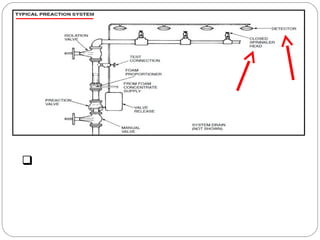


Fire sprinkler systems have been in use since the late 1880s to provide fire protection for buildings and their occupants. There are four main types of sprinkler systems - wet pipe, dry pipe, deluge, and pre-action - each with different components and activation methods appropriate for various conditions. Sprinkler systems are required by building codes and are highly effective at controlling fires, with most being contained by five or fewer sprinkler heads. Proper installation, maintenance, and oversight by professionals is necessary for systems to function as designed in the event of a fire emergency.


![UNIT 8 hose[Read-Only].pptx](https://cdn.slidesharecdn.com/ss_thumbnails/unit8hoseread-only-230306084034-944757c6-thumbnail.jpg?width=640&height=640&fit=bounds)