Downloaded 140 times
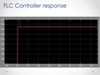
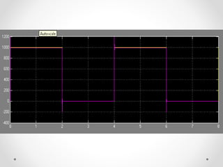
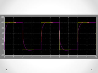
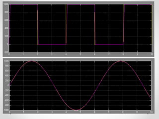
![FLC Controller
Cd k= 1*10^(-14), Cd k1= 1000, Sat=[-6000, 6000] (optimal response)](https://image.slidesharecdn.com/finalbldc-presentation-140525180238-phpapp02/85/Integrated-fuzzy-logic-controller-for-a-Brushless-DC-Servomotor-system-16-320.jpg)
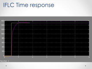
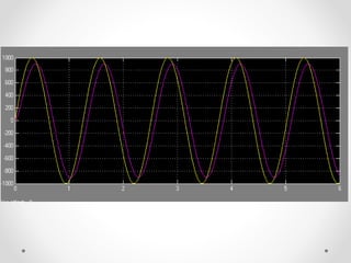
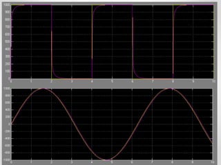
![IFLC Controller
Cd k= 1*10^(-14), Sat=[-1000, 1000], C-S: Kp= 30, KI= 88.107, Kd=1.00
C-C: Kp=1.00, Ki= 350.941 (optimal response)](https://image.slidesharecdn.com/finalbldc-presentation-140525180238-phpapp02/85/Integrated-fuzzy-logic-controller-for-a-Brushless-DC-Servomotor-system-21-320.jpg)
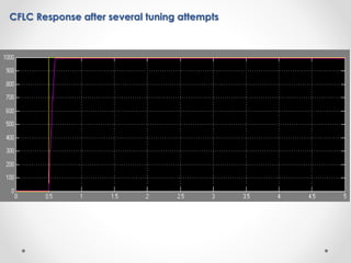
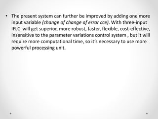


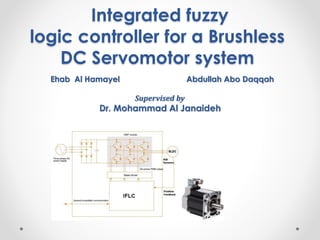
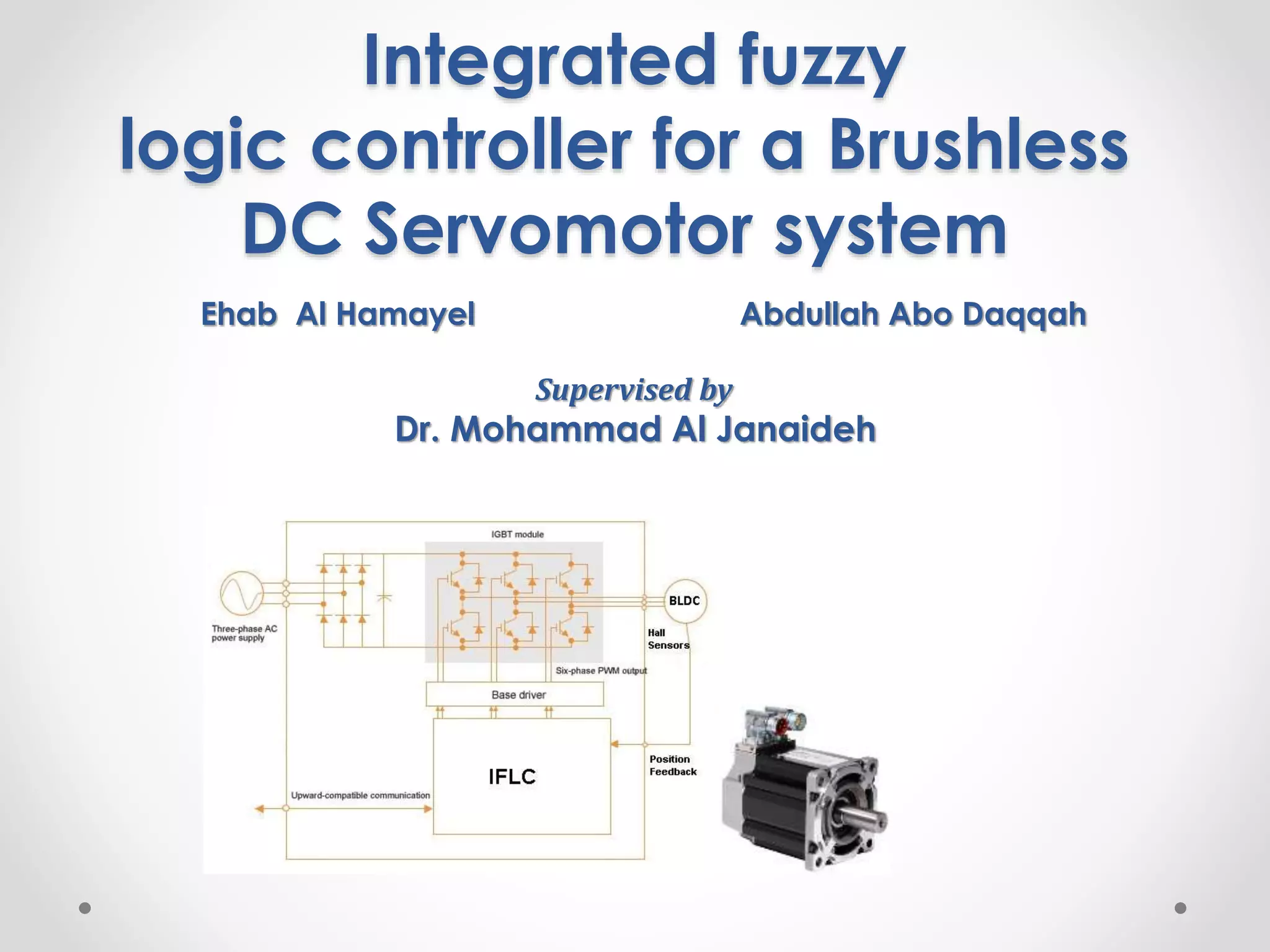
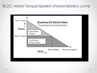
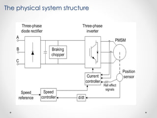
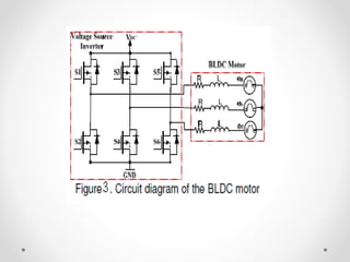
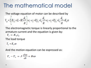
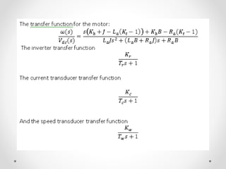
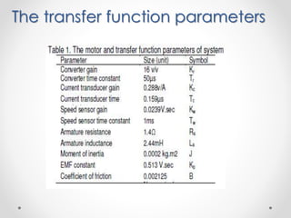
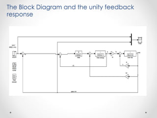
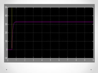
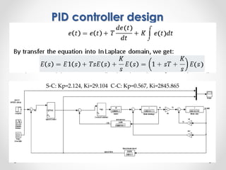
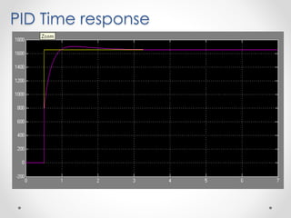
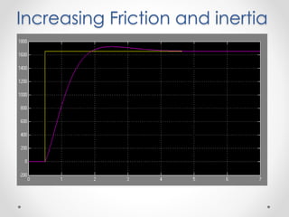
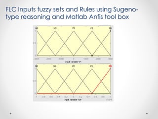
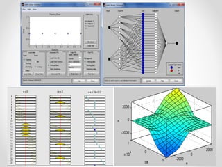
The document presents the design of an integrated fuzzy logic controller (IFLC) for controlling the rotation speed of brushless DC servomotors, emphasizing its superior performance over conventional PID and fuzzy logic controllers. It discusses the mathematical modeling, control system design, and simulation results indicating enhanced response accuracy. Future improvements may involve adding an additional input variable for further robustness and flexibility, albeit at the cost of increased computational demands.