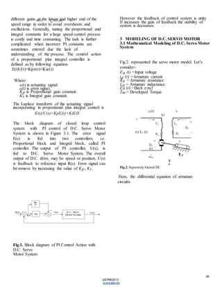
SlideShare a Scribd company logo
1 of 6
95 
Design of Pi Controller To Minimize The Speed 
Error of D.C. Servo Motor 
Abstract— This study present efficient method for speed control of a D.C. Servo Motor using PI 
controller. Design of a PI controller requires minimizing the error. The experimental is used to obtain 
the transfer function to design the PI controller. The effectiveness of the design is validated using 
MATLAB/Simulink. This new design method gives us a simple and powerful way to design a speed 
controller for a servo – motor. This paper identifies and describes the design choices related to a PI 
controller for a D.C. servo motor. D.C. servo motor is also variable speed drive, and paper presents 
variable speed with minimizing speed error. 
Index Terms— Control System, Proportional-Integral (P-I) controller, Speed control of d.c motor. 
IJSTR©2012 
www.ijstr.org 
INTRODUCTION 
Everyone recognizes the vital role played by 
electrical motors in the development of industrial 
systems. There are five major 
types of D.C motors in general use, which are the 
separately excited D.C motor, the shunt D.C 
motor, the permanent – 
magnet D. motor, the series D.C motor and the 
compound D.C 
motor. The D.C machine is the first practical device 
to convert electrical power into mechanical power, 
and vice versa. Inherently straightforward operating 
characteristics, flexible performance and efficiency 
encouraged the use of D.C motors in many types 
of industrial drive application. Most multi-purpose 
production machines benefit from 
adjustable speed control, since frequently their 
speeds must change to optimize the machine process 
or adapt it to various tasks for improved product 
quality, production speed. The Proportional- 
Integral (P-I) controller is one of the conventional 
controllers and it has been widely used for the speed 
control of dc motor drives [3]. The major features 
of the P-I controller are its ability to maintain a 
zero steady-state error to a step change in 
reference. Due to sudden change in load torque and 
the sensitivity to controller gains KR IR 
and KRPR have been proposed for the 
speed control of dc motors [8]. 
2 LITERATURE REVIEW 
2.1 Servo Motor Description 
Electric motors can be classified by their functions 
as servomotors, gear motors, and so forth, and by 
their electrical configurations as DC (direct 
current) and AC (alternating current motors. 
Servomotor is a motor used for position or speed 
control in closed loop control systems. The 
requirement from a servomotor is to turnover a wide 
range of speeds and also to perform position and 
speed. DC servo motors have been used generally 
at the computers, numeric control machines, 
industrial equipments, weapon industry, and speed 
control of alternators, control mechanism of full 
automatic regulators as the first starter, starting 
systems quickly and correctly [4] [6]. Some 
properties of DC servo motors are the same, like 
inertia, physical structure, shaft resonance and 
shaft characteristics, their electrical and physical 
constants are variable. The velocity and position 
tolerance of servo motors which are used at the 
control systems are nearly the same. It has 
implemented proportional integral, fuzzy logic 
and adaptive neuro fuzzy inference system 
respectively at the variable working situations to the 
simulation model which has prepared at the 
Matlab programmers for improvement the servo 
motor performance. 
2.2 Proportional plus Integral Controller 
Description Proportional plus Integral (PI) 
controllers are widely used in industrial practice 
for more than 60 years. The development went 
from pneumatic through analogue to digital 
controllers, but the control algorithm is in fact the 
same. The PI controller is standard and proved 
solution for the most industrial application. The 
main reason is its relatively simple structure, which 
can be easily understood and implemented in 
practice, and that many sophisticated control 
strategies, such as model predictive control, are 
based on it. An application with large speed 
capabilities requires different PI gains than 
an application which operates at a fixed speed. 
In addition, industrial equipment that are 
operating over wide range of speeds, requires
96 
IJSTR©2012 
www.ijstr.org 
different gains at the lower and higher end of the 
speed range in order to avoid overshoots and 
oscillations. Generally, tuning the proportional and 
integral constants for a large speed control process 
is costly and time consuming. The task is further 
complicated when incorrect PI constants are 
sometimes entered due the lack of 
understanding of the process. The control action 
of a proportional plus integral controller is 
defined as by following equation. 
E(t)U(t)=Kpe(t)+Kie(t) 
Where: 
u(t) is actuating signal. 
e(t) is error signal. 
Kp is Proportional gain constant. 
Ki is Integral gain constant. 
The Laplace transform of the actuating signal 
incorporating in proportional plus integral control is 
E(s)/U(s)=KpE(s)+KiE(S 
The block diagram of closed loop control 
system with PI control of D.C. Servo Motor 
System is shown in Figure 3.1. The error signal 
E(s) is fed into two controllers, i.e. 
Proportional block and Integral block, called PI 
controller. The output of PI controller, U(s), is 
fed to D.C. Servo Motor System. The overall 
output of D.C. drive, may be speed or position, C(s) 
is feedback to reference input R(s). Error signal can 
be remove by increasing the value of Kp , Ki . 
Fig.1. Block diagram of PI Control Action with 
D.C. Servo 
Motor System 
However the feedback of control system is unity. 
If increases the gain of feedback the stability of 
system is decreases. 
3 MODELING OF D.C. SERVO MOTOR 
3.1 Mathematical Modeling of D.C. Servo Motor 
System 
Fig.2. represented the servo motor model. Let’s 
consider:- 
Ea (t) =Input voltage 
ia (t) =Armature current 
Ra = Armature resistance 
La = Armature inductance 
Eb (t) =Back e.m.f 
Tm = Developed Torque 
ia (t) if 
(t) 
+ 
Ef 
(t) Ea (t) 
Eb 
(t) 
_ 
ωm 
T 
m 
Fig.2. Separately Excited DC 
Here, the differential equation of armature 
circuitis
97 
IJSTR©2012 
www.ijstr.org 
Ea (t) =Ra .i a (t) + L a .di a (t) + Eb (t) (1) 
dt 
The Torque equation is- 
Tm (t) = J.dωm (t) + B.ωm (t) (2) 
dt 
The torque developed by motor is proportional to the 
product 
of the armature current and field 
current i.e. 
Tm (t) = Kf .i f .i a (3) 
Where, Kf is constant. 
In armature – controlled D.C. motor the field current (i 
f ) is kept constant i.e. 
Tm = KT.i a (4) 
Where, KT = Kf .if is torque constant. 
The back e.m.f. of motor is proportional to the 
speed i.e. 
Eb (t) = Kb . ωm (5) 
Where, Kb is back e.m.f. constant. 
In order to create the block diagram of system initial 
conditions are zero and Laplace transform is 
implemented to the equations. i.e. 
Ea (s) = Ra .Ia (s) + sLa .Ia 
(s) + Eb (s) 
Ia (s) = Ea (s) - Eb (s) 
sLa +Ra 
Tm (s) = sJ.ωm (s) + B.ωm (s) 
ωm (s) = Tm (s) 
(7)sJ + B 
Tm (s) = KT.Ia (s) 
(8) 
Eb (s) = Kb . ωm (s) 
(9) 
The forward path blocks are the transfer function of 
following: 
Ia (s) = 1 
Ea (s) - Eb (s) sLa + Ra 
Tm (s) = KT 
Ia (s) 
ωm (s) = 1 
Tm (s) sJ + B 
The feedback path block is the transfer function of 
following: 
E b (s) = Kb 
ωm (s) 
Fig.3. only show the block diagram of armature 
controlled. 
4.1 D.C. Servo Motor Parameter 
The motor used in this experiment is an 110V D.C. 
motor with no load speed of 4050 rpm. 
Parameter Value 
R-resistance 0.6 Ω 
L-inductance 8 mH 
J-moment of inertia 0.0465 kg.m2 
Kt -torque constant 0.052 Nm/A 
Kb -electromotive force constant 0.1 V/rad/s 
B-viscous friction coefficient 0.004 N.m/rad/s 
d.c motor
98 
4.1 Simulink 
Model 
Fig.4 shows the simulink model of D.C. Servo Motor 
system. In this model two PI controllers is used. First 
PI controller is used for control the speed and second 
PI controller is use to control the armature current. The 
speed response at different reference input 110V to 
220V and 110V to 55V as shown in Fig.5 and Fig.7 
respectively. And corresponding minimized speed error 
as in Fig.6 and Fig.8. 
IJSTR©2012 
www.ijstr.org 
Fig.4. Simulink Model of D.C. Servo Motor 
4.2 Responses 
4.2.1 Speed Response (Ref. input 110V to 
220V) 
The speed response of D.C. servo motor is shown 
below. The 
rated reference input 110V for 5 second and then 
suddenly increase input up to 220V for 4 second, 
the corresponding speed is found. The value of 
proportional gain and integral gain is adjusted to 
minimized overshoots, rise time, peak time and 
settling time. Due to minimization of transient 
specifications the system becomes fast and steady 
state easily occurs. 
Fig.5. Speed Response of D.C. Servo Motor 
4.2.2 Speed Error Response (Ref. input 110V to 
220V) 
The minimized seed error response at 110V to 220V 
shown in Fig.6. From Fig.5 and Fig.6, when 
reference input increase from 0V to 110V, the speed 
error increase 0V to 110V. But when speed become 
constant (become steady state) the error slightly fall 
and become zero. When reference input increase from 
110V to 220V, the speed error increase 0V to 110V. 
But when speed become constant (become steady 
state) the error slightly fall and become zero. 
Fig.6. Speed Error of D.C. Servo Motor 
4.2.3 Speed Response (Ref. input 110V to 
55V) 
The speed response of D.C. servo motor is shown 
below. The rated reference input 110V for 5 second 
and then suddenly decrease input up to 55V for 4 
second, the corresponding speed is found. The value 
of proportional gain and integral gain is adjusted to 
minimized overshoots, rise time, peak time and 
settling time. Due to minimization of transient 
specifications the system becomes fast and steady 
state easily occurs. 
Fig.7. Speed Response of D.C. Servo Motor 
4.2.4 Speed Error Response (Ref. input 110V 
to 55V) 
The minimized seed error response at 110V to 55V 
shown in Fig.8. From Fig.7 and Fig.8, when 
reference input increase from 0V to 110V, the speed 
error increase 0V to 110V. But when speed become 
constant (become steady state) the error slightly fall 
and become zero. When reference input decrease from 
110V to 55V, the speed error decrease from 0V to 
55V. But when speed become constant (become steady 
state) the error slightly increase and become zero.
99 
IJSTR©2012 
www.ijstr.org 
Fig.8. Speed Error of D.C. Servo Motor 
CONCLUSI0N 
A PI controller for a D.C. servomotor has been 
studied. The performance of PI controller was 
evaluated by simulation. The 
controller gain was adjusted to obtain 
minimized error 
responses. The results show significant improvement 
in maintaining performance of approximate zero 
overshoot, minimum stabilizing time. 
ACKNOWLEDGMENT 
I feel a sense of deep self-satisfaction and a great 
experience of having accomplished my paper 
entitled “DESIGN OF PI 
CONTROLLER TO MINIMIZE THE SPEED 
ERROR OF D.C. SERVO MOTOR”.
10 
IJSTR©2012 0 
www.ijstr.org

More Related Content

What's hot

What's hot (19)

Pid controller
Pid controllerPid controller
Pid controller
 
Pid controller bp ganthia
Pid controller bp ganthiaPid controller bp ganthia
Pid controller bp ganthia
 
PID Controllers
PID ControllersPID Controllers
PID Controllers
 
pid controller
 pid controller pid controller
pid controller
 
Pid controller
Pid controllerPid controller
Pid controller
 
Control system basics, block diagram and signal flow graph
Control system basics, block diagram and signal flow graphControl system basics, block diagram and signal flow graph
Control system basics, block diagram and signal flow graph
 
Pid controller
Pid controllerPid controller
Pid controller
 
Pid controller bp ganthia
Pid controller bp ganthiaPid controller bp ganthia
Pid controller bp ganthia
 
Level Control of Tank System Using PID Controller-A Review
Level Control of Tank System Using PID Controller-A ReviewLevel Control of Tank System Using PID Controller-A Review
Level Control of Tank System Using PID Controller-A Review
 
Week 14 pid may 24 2016 pe 3032
Week  14 pid  may 24 2016 pe 3032Week  14 pid  may 24 2016 pe 3032
Week 14 pid may 24 2016 pe 3032
 
Controller Tuning Method for Non-Linear Conical Tank System
Controller Tuning Method for Non-Linear Conical Tank SystemController Tuning Method for Non-Linear Conical Tank System
Controller Tuning Method for Non-Linear Conical Tank System
 
Pid control
Pid controlPid control
Pid control
 
Tuning of pid controller
Tuning of pid controllerTuning of pid controller
Tuning of pid controller
 
Pid controllers
Pid controllersPid controllers
Pid controllers
 
Pid control by Adarsh singh
Pid control  by Adarsh singhPid control  by Adarsh singh
Pid control by Adarsh singh
 
Pid controller
Pid controllerPid controller
Pid controller
 
Tuning of pid
Tuning of pidTuning of pid
Tuning of pid
 
PID Control
PID ControlPID Control
PID Control
 
PID Temperature Controller
PID Temperature ControllerPID Temperature Controller
PID Temperature Controller
 

Viewers also liked

Speed Control of DC Motor under Varying Load Using PID Controller
Speed Control of DC Motor under Varying Load Using PID ControllerSpeed Control of DC Motor under Varying Load Using PID Controller
Speed Control of DC Motor under Varying Load Using PID ControllerCSCJournals
 
6. performance analysis of pd, pid controllers for speed control of dc motor
6. performance analysis of pd, pid controllers for speed control of dc motor6. performance analysis of pd, pid controllers for speed control of dc motor
6. performance analysis of pd, pid controllers for speed control of dc motork srikanth
 
Configuration of pid controller for speed control of dc motor utilizing optim...
Configuration of pid controller for speed control of dc motor utilizing optim...Configuration of pid controller for speed control of dc motor utilizing optim...
Configuration of pid controller for speed control of dc motor utilizing optim...Santosh Suman
 
Report pid controller dc motor
Report pid controller dc motorReport pid controller dc motor
Report pid controller dc motorchea kimsairng
 
speed control of dc motor
speed control of dc motorspeed control of dc motor
speed control of dc motorvikash512
 
Matlab dc motor modeling
Matlab dc motor modelingMatlab dc motor modeling
Matlab dc motor modelingAmeen San
 
Speed control of dc motor using matlab
Speed control of dc motor using matlabSpeed control of dc motor using matlab
Speed control of dc motor using matlabShridhar kulkarni
 
Embedded systems notes
Embedded systems notesEmbedded systems notes
Embedded systems notesShikha Sharma
 
Embedded System Design Notes written by Arun Kumar G, Associate Professor, De...
Embedded System Design Notes written by Arun Kumar G, Associate Professor, De...Embedded System Design Notes written by Arun Kumar G, Associate Professor, De...
Embedded System Design Notes written by Arun Kumar G, Associate Professor, De...Arunkumar Gowdru
 
Embedded systems class notes
Embedded systems  class notes Embedded systems  class notes
Embedded systems class notes Dr.YNM
 
Report on speed control of d.c. motor using pwm method
Report on speed control of d.c. motor using pwm methodReport on speed control of d.c. motor using pwm method
Report on speed control of d.c. motor using pwm methodshivam singh
 
Doc speed control of a dc motor using micro controller 8051
Doc speed control of a dc motor using micro controller 8051Doc speed control of a dc motor using micro controller 8051
Doc speed control of a dc motor using micro controller 8051embdnew
 
Speed control of DC Machine
Speed control of DC MachineSpeed control of DC Machine
Speed control of DC MachineSHAHBAAZ AHMED
 

Viewers also liked (18)

Speed Control of DC Motor under Varying Load Using PID Controller
Speed Control of DC Motor under Varying Load Using PID ControllerSpeed Control of DC Motor under Varying Load Using PID Controller
Speed Control of DC Motor under Varying Load Using PID Controller
 
Seminar (1)
Seminar (1)Seminar (1)
Seminar (1)
 
6. performance analysis of pd, pid controllers for speed control of dc motor
6. performance analysis of pd, pid controllers for speed control of dc motor6. performance analysis of pd, pid controllers for speed control of dc motor
6. performance analysis of pd, pid controllers for speed control of dc motor
 
Configuration of pid controller for speed control of dc motor utilizing optim...
Configuration of pid controller for speed control of dc motor utilizing optim...Configuration of pid controller for speed control of dc motor utilizing optim...
Configuration of pid controller for speed control of dc motor utilizing optim...
 
Report pid controller dc motor
Report pid controller dc motorReport pid controller dc motor
Report pid controller dc motor
 
speed control of dc motor
speed control of dc motorspeed control of dc motor
speed control of dc motor
 
Speed Control Of DC Motor
Speed Control Of DC MotorSpeed Control Of DC Motor
Speed Control Of DC Motor
 
Matlab dc motor modeling
Matlab dc motor modelingMatlab dc motor modeling
Matlab dc motor modeling
 
Speed control of dc motor using matlab
Speed control of dc motor using matlabSpeed control of dc motor using matlab
Speed control of dc motor using matlab
 
Embedded systems notes
Embedded systems notesEmbedded systems notes
Embedded systems notes
 
Automatic speed control of DC motor
Automatic speed control of DC motorAutomatic speed control of DC motor
Automatic speed control of DC motor
 
Embedded System Design Notes written by Arun Kumar G, Associate Professor, De...
Embedded System Design Notes written by Arun Kumar G, Associate Professor, De...Embedded System Design Notes written by Arun Kumar G, Associate Professor, De...
Embedded System Design Notes written by Arun Kumar G, Associate Professor, De...
 
3rd to 8th semester Electronics and Communication Engineering (2010 Scheme) S...
3rd to 8th semester Electronics and Communication Engineering (2010 Scheme) S...3rd to 8th semester Electronics and Communication Engineering (2010 Scheme) S...
3rd to 8th semester Electronics and Communication Engineering (2010 Scheme) S...
 
Speed Controller for DC Motor
Speed Controller for DC MotorSpeed Controller for DC Motor
Speed Controller for DC Motor
 
Embedded systems class notes
Embedded systems  class notes Embedded systems  class notes
Embedded systems class notes
 
Report on speed control of d.c. motor using pwm method
Report on speed control of d.c. motor using pwm methodReport on speed control of d.c. motor using pwm method
Report on speed control of d.c. motor using pwm method
 
Doc speed control of a dc motor using micro controller 8051
Doc speed control of a dc motor using micro controller 8051Doc speed control of a dc motor using micro controller 8051
Doc speed control of a dc motor using micro controller 8051
 
Speed control of DC Machine
Speed control of DC MachineSpeed control of DC Machine
Speed control of DC Machine
 

Similar to DC Motor Speed Control Using PI Controller

Adaptive Fuzzy PID Regulator for the Speed Control of Brushless Dc Motor
Adaptive Fuzzy PID Regulator for the Speed Control of Brushless Dc MotorAdaptive Fuzzy PID Regulator for the Speed Control of Brushless Dc Motor
Adaptive Fuzzy PID Regulator for the Speed Control of Brushless Dc MotorIOSR Journals
 
Simulation DC Motor Speed Control System by using PID Controller
Simulation DC Motor Speed Control System by using PID ControllerSimulation DC Motor Speed Control System by using PID Controller
Simulation DC Motor Speed Control System by using PID Controllerijtsrd
 
Paper id 24201493
Paper id 24201493Paper id 24201493
Paper id 24201493IJRAT
 
Speed Control of Brushless Dc Motor Using Fuzzy Logic Controller
Speed Control of Brushless Dc Motor Using Fuzzy Logic ControllerSpeed Control of Brushless Dc Motor Using Fuzzy Logic Controller
Speed Control of Brushless Dc Motor Using Fuzzy Logic Controlleriosrjce
 
Performance analysis of Fuzzy logic based speed control of DC motor
Performance analysis of Fuzzy logic based speed control of DC motorPerformance analysis of Fuzzy logic based speed control of DC motor
Performance analysis of Fuzzy logic based speed control of DC motorIOSR Journals
 
Modified Chattering Free Sliding Mode Control of DC Motor
Modified Chattering Free Sliding Mode Control of DC MotorModified Chattering Free Sliding Mode Control of DC Motor
Modified Chattering Free Sliding Mode Control of DC MotorIJMER
 
Speed control of dc motor using relay feedback tuned pi
Speed control of dc motor using relay feedback tuned piSpeed control of dc motor using relay feedback tuned pi
Speed control of dc motor using relay feedback tuned piAlexander Decker
 
STATOR FLUX OPTIMIZATION ON DIRECT TORQUE CONTROL WITH FUZZY LOGIC
STATOR FLUX OPTIMIZATION ON DIRECT TORQUE CONTROL WITH FUZZY LOGIC STATOR FLUX OPTIMIZATION ON DIRECT TORQUE CONTROL WITH FUZZY LOGIC
STATOR FLUX OPTIMIZATION ON DIRECT TORQUE CONTROL WITH FUZZY LOGIC cscpconf
 
Rotor Resistance Adaptation Scheme Using Neural Learning Algorithm for a Fuzz...
Rotor Resistance Adaptation Scheme Using Neural Learning Algorithm for a Fuzz...Rotor Resistance Adaptation Scheme Using Neural Learning Algorithm for a Fuzz...
Rotor Resistance Adaptation Scheme Using Neural Learning Algorithm for a Fuzz...IOSR Journals
 
Speed Control of Induction Motor by Using Intelligence Techniques
Speed Control of Induction Motor by Using Intelligence TechniquesSpeed Control of Induction Motor by Using Intelligence Techniques
Speed Control of Induction Motor by Using Intelligence TechniquesIJERA Editor
 
Servo Fundamentals
Servo FundamentalsServo Fundamentals
Servo Fundamentalspurnima saha
 
A NEW APPROACH TO DTC METHOD FOR BLDC MOTOR ADJUSTABLE SPEED DRIVES
A NEW APPROACH TO DTC METHOD FOR BLDC MOTOR ADJUSTABLE SPEED DRIVESA NEW APPROACH TO DTC METHOD FOR BLDC MOTOR ADJUSTABLE SPEED DRIVES
A NEW APPROACH TO DTC METHOD FOR BLDC MOTOR ADJUSTABLE SPEED DRIVEScscpconf
 
DTC Scheme for a Four-Switch Inverter-Fed PMBLDC Motor Emulating the Six-Swit...
DTC Scheme for a Four-Switch Inverter-Fed PMBLDC Motor Emulating the Six-Swit...DTC Scheme for a Four-Switch Inverter-Fed PMBLDC Motor Emulating the Six-Swit...
DTC Scheme for a Four-Switch Inverter-Fed PMBLDC Motor Emulating the Six-Swit...IJRST Journal
 
Mathematical Modelling and Simulation of Compensator for Dynamical System
Mathematical Modelling and Simulation of Compensator for Dynamical SystemMathematical Modelling and Simulation of Compensator for Dynamical System
Mathematical Modelling and Simulation of Compensator for Dynamical SystemIRJET Journal
 
IRJET-Comparison between Scalar & Vector Control Technique for Induction Moto...
IRJET-Comparison between Scalar & Vector Control Technique for Induction Moto...IRJET-Comparison between Scalar & Vector Control Technique for Induction Moto...
IRJET-Comparison between Scalar & Vector Control Technique for Induction Moto...IRJET Journal
 
Speed control of Separately Excited DC Motor using various Conventional Contr...
Speed control of Separately Excited DC Motor using various Conventional Contr...Speed control of Separately Excited DC Motor using various Conventional Contr...
Speed control of Separately Excited DC Motor using various Conventional Contr...IJERA Editor
 
International Journal of Engineering Research and Development (IJERD)
International Journal of Engineering Research and Development (IJERD)International Journal of Engineering Research and Development (IJERD)
International Journal of Engineering Research and Development (IJERD)IJERD Editor
 

Similar to DC Motor Speed Control Using PI Controller (20)

C010121017
C010121017C010121017
C010121017
 
Adaptive Fuzzy PID Regulator for the Speed Control of Brushless Dc Motor
Adaptive Fuzzy PID Regulator for the Speed Control of Brushless Dc MotorAdaptive Fuzzy PID Regulator for the Speed Control of Brushless Dc Motor
Adaptive Fuzzy PID Regulator for the Speed Control of Brushless Dc Motor
 
Simulation DC Motor Speed Control System by using PID Controller
Simulation DC Motor Speed Control System by using PID ControllerSimulation DC Motor Speed Control System by using PID Controller
Simulation DC Motor Speed Control System by using PID Controller
 
Paper id 24201493
Paper id 24201493Paper id 24201493
Paper id 24201493
 
J010616573
J010616573J010616573
J010616573
 
Speed Control of Brushless Dc Motor Using Fuzzy Logic Controller
Speed Control of Brushless Dc Motor Using Fuzzy Logic ControllerSpeed Control of Brushless Dc Motor Using Fuzzy Logic Controller
Speed Control of Brushless Dc Motor Using Fuzzy Logic Controller
 
Performance analysis of Fuzzy logic based speed control of DC motor
Performance analysis of Fuzzy logic based speed control of DC motorPerformance analysis of Fuzzy logic based speed control of DC motor
Performance analysis of Fuzzy logic based speed control of DC motor
 
Design and implementation speed control system of DC Motor based on PID contr...
Design and implementation speed control system of DC Motor based on PID contr...Design and implementation speed control system of DC Motor based on PID contr...
Design and implementation speed control system of DC Motor based on PID contr...
 
Modified Chattering Free Sliding Mode Control of DC Motor
Modified Chattering Free Sliding Mode Control of DC MotorModified Chattering Free Sliding Mode Control of DC Motor
Modified Chattering Free Sliding Mode Control of DC Motor
 
Speed control of dc motor using relay feedback tuned pi
Speed control of dc motor using relay feedback tuned piSpeed control of dc motor using relay feedback tuned pi
Speed control of dc motor using relay feedback tuned pi
 
STATOR FLUX OPTIMIZATION ON DIRECT TORQUE CONTROL WITH FUZZY LOGIC
STATOR FLUX OPTIMIZATION ON DIRECT TORQUE CONTROL WITH FUZZY LOGIC STATOR FLUX OPTIMIZATION ON DIRECT TORQUE CONTROL WITH FUZZY LOGIC
STATOR FLUX OPTIMIZATION ON DIRECT TORQUE CONTROL WITH FUZZY LOGIC
 
Rotor Resistance Adaptation Scheme Using Neural Learning Algorithm for a Fuzz...
Rotor Resistance Adaptation Scheme Using Neural Learning Algorithm for a Fuzz...Rotor Resistance Adaptation Scheme Using Neural Learning Algorithm for a Fuzz...
Rotor Resistance Adaptation Scheme Using Neural Learning Algorithm for a Fuzz...
 
Speed Control of Induction Motor by Using Intelligence Techniques
Speed Control of Induction Motor by Using Intelligence TechniquesSpeed Control of Induction Motor by Using Intelligence Techniques
Speed Control of Induction Motor by Using Intelligence Techniques
 
Servo Fundamentals
Servo FundamentalsServo Fundamentals
Servo Fundamentals
 
A NEW APPROACH TO DTC METHOD FOR BLDC MOTOR ADJUSTABLE SPEED DRIVES
A NEW APPROACH TO DTC METHOD FOR BLDC MOTOR ADJUSTABLE SPEED DRIVESA NEW APPROACH TO DTC METHOD FOR BLDC MOTOR ADJUSTABLE SPEED DRIVES
A NEW APPROACH TO DTC METHOD FOR BLDC MOTOR ADJUSTABLE SPEED DRIVES
 
DTC Scheme for a Four-Switch Inverter-Fed PMBLDC Motor Emulating the Six-Swit...
DTC Scheme for a Four-Switch Inverter-Fed PMBLDC Motor Emulating the Six-Swit...DTC Scheme for a Four-Switch Inverter-Fed PMBLDC Motor Emulating the Six-Swit...
DTC Scheme for a Four-Switch Inverter-Fed PMBLDC Motor Emulating the Six-Swit...
 
Mathematical Modelling and Simulation of Compensator for Dynamical System
Mathematical Modelling and Simulation of Compensator for Dynamical SystemMathematical Modelling and Simulation of Compensator for Dynamical System
Mathematical Modelling and Simulation of Compensator for Dynamical System
 
IRJET-Comparison between Scalar & Vector Control Technique for Induction Moto...
IRJET-Comparison between Scalar & Vector Control Technique for Induction Moto...IRJET-Comparison between Scalar & Vector Control Technique for Induction Moto...
IRJET-Comparison between Scalar & Vector Control Technique for Induction Moto...
 
Speed control of Separately Excited DC Motor using various Conventional Contr...
Speed control of Separately Excited DC Motor using various Conventional Contr...Speed control of Separately Excited DC Motor using various Conventional Contr...
Speed control of Separately Excited DC Motor using various Conventional Contr...
 
International Journal of Engineering Research and Development (IJERD)
International Journal of Engineering Research and Development (IJERD)International Journal of Engineering Research and Development (IJERD)
International Journal of Engineering Research and Development (IJERD)
 

More from Krishnaveni Reddy

More from Krishnaveni Reddy (6)

Future awareness after grduation
Future awareness after grduationFuture awareness after grduation
Future awareness after grduation
 
the substation components study
the substation components study the substation components study
the substation components study
 
Presentation of bpl
Presentation of bplPresentation of bpl
Presentation of bpl
 
Tech seminar
Tech seminarTech seminar
Tech seminar
 
Artificial passenger ieee format
Artificial passenger ieee formatArtificial passenger ieee format
Artificial passenger ieee format
 
Voltagedoubler
VoltagedoublerVoltagedoubler
Voltagedoubler
 

Recently uploaded

Call Girls in Nagpur Suman Call 7001035870 Meet With Nagpur Escorts
Call Girls in Nagpur Suman Call 7001035870 Meet With Nagpur EscortsCall Girls in Nagpur Suman Call 7001035870 Meet With Nagpur Escorts
Call Girls in Nagpur Suman Call 7001035870 Meet With Nagpur EscortsCall Girls in Nagpur High Profile
 
High Profile Call Girls Nagpur Meera Call 7001035870 Meet With Nagpur Escorts
High Profile Call Girls Nagpur Meera Call 7001035870 Meet With Nagpur EscortsHigh Profile Call Girls Nagpur Meera Call 7001035870 Meet With Nagpur Escorts
High Profile Call Girls Nagpur Meera Call 7001035870 Meet With Nagpur EscortsCall Girls in Nagpur High Profile
 
MANUFACTURING PROCESS-II UNIT-2 LATHE MACHINE
MANUFACTURING PROCESS-II UNIT-2 LATHE MACHINEMANUFACTURING PROCESS-II UNIT-2 LATHE MACHINE
MANUFACTURING PROCESS-II UNIT-2 LATHE MACHINESIVASHANKAR N
 
Introduction to Multiple Access Protocol.pptx
Introduction to Multiple Access Protocol.pptxIntroduction to Multiple Access Protocol.pptx
Introduction to Multiple Access Protocol.pptxupamatechverse
 
What are the advantages and disadvantages of membrane structures.pptx
What are the advantages and disadvantages of membrane structures.pptxWhat are the advantages and disadvantages of membrane structures.pptx
What are the advantages and disadvantages of membrane structures.pptxwendy cai
 
main PPT.pptx of girls hostel security using rfid
main PPT.pptx of girls hostel security using rfidmain PPT.pptx of girls hostel security using rfid
main PPT.pptx of girls hostel security using rfidNikhilNagaraju
 
(SHREYA) Chakan Call Girls Just Call 7001035870 [ Cash on Delivery ] Pune Esc...
(SHREYA) Chakan Call Girls Just Call 7001035870 [ Cash on Delivery ] Pune Esc...(SHREYA) Chakan Call Girls Just Call 7001035870 [ Cash on Delivery ] Pune Esc...
(SHREYA) Chakan Call Girls Just Call 7001035870 [ Cash on Delivery ] Pune Esc...ranjana rawat
 
Call Girls Service Nagpur Tanvi Call 7001035870 Meet With Nagpur Escorts
Call Girls Service Nagpur Tanvi Call 7001035870 Meet With Nagpur EscortsCall Girls Service Nagpur Tanvi Call 7001035870 Meet With Nagpur Escorts
Call Girls Service Nagpur Tanvi Call 7001035870 Meet With Nagpur EscortsCall Girls in Nagpur High Profile
 
Porous Ceramics seminar and technical writing
Porous Ceramics seminar and technical writingPorous Ceramics seminar and technical writing
Porous Ceramics seminar and technical writingrakeshbaidya232001
 
(ANJALI) Dange Chowk Call Girls Just Call 7001035870 [ Cash on Delivery ] Pun...
(ANJALI) Dange Chowk Call Girls Just Call 7001035870 [ Cash on Delivery ] Pun...(ANJALI) Dange Chowk Call Girls Just Call 7001035870 [ Cash on Delivery ] Pun...
(ANJALI) Dange Chowk Call Girls Just Call 7001035870 [ Cash on Delivery ] Pun...ranjana rawat
 
Architect Hassan Khalil Portfolio for 2024
Architect Hassan Khalil Portfolio for 2024Architect Hassan Khalil Portfolio for 2024
Architect Hassan Khalil Portfolio for 2024hassan khalil
 
Coefficient of Thermal Expansion and their Importance.pptx
Coefficient of Thermal Expansion and their Importance.pptxCoefficient of Thermal Expansion and their Importance.pptx
Coefficient of Thermal Expansion and their Importance.pptxAsutosh Ranjan
 
VIP Call Girls Service Hitech City Hyderabad Call +91-8250192130
VIP Call Girls Service Hitech City Hyderabad Call +91-8250192130VIP Call Girls Service Hitech City Hyderabad Call +91-8250192130
VIP Call Girls Service Hitech City Hyderabad Call +91-8250192130Suhani Kapoor
 
GDSC ASEB Gen AI study jams presentation
GDSC ASEB Gen AI study jams presentationGDSC ASEB Gen AI study jams presentation
GDSC ASEB Gen AI study jams presentationGDSCAESB
 
OSVC_Meta-Data based Simulation Automation to overcome Verification Challenge...
OSVC_Meta-Data based Simulation Automation to overcome Verification Challenge...OSVC_Meta-Data based Simulation Automation to overcome Verification Challenge...
OSVC_Meta-Data based Simulation Automation to overcome Verification Challenge...Soham Mondal
 
Analog to Digital and Digital to Analog Converter
Analog to Digital and Digital to Analog ConverterAnalog to Digital and Digital to Analog Converter
Analog to Digital and Digital to Analog ConverterAbhinavSharma374939
 
Model Call Girl in Narela Delhi reach out to us at 🔝8264348440🔝
Model Call Girl in Narela Delhi reach out to us at 🔝8264348440🔝Model Call Girl in Narela Delhi reach out to us at 🔝8264348440🔝
Model Call Girl in Narela Delhi reach out to us at 🔝8264348440🔝soniya singh
 

Recently uploaded (20)

Call Girls in Nagpur Suman Call 7001035870 Meet With Nagpur Escorts
Call Girls in Nagpur Suman Call 7001035870 Meet With Nagpur EscortsCall Girls in Nagpur Suman Call 7001035870 Meet With Nagpur Escorts
Call Girls in Nagpur Suman Call 7001035870 Meet With Nagpur Escorts
 
High Profile Call Girls Nagpur Meera Call 7001035870 Meet With Nagpur Escorts
High Profile Call Girls Nagpur Meera Call 7001035870 Meet With Nagpur EscortsHigh Profile Call Girls Nagpur Meera Call 7001035870 Meet With Nagpur Escorts
High Profile Call Girls Nagpur Meera Call 7001035870 Meet With Nagpur Escorts
 
MANUFACTURING PROCESS-II UNIT-2 LATHE MACHINE
MANUFACTURING PROCESS-II UNIT-2 LATHE MACHINEMANUFACTURING PROCESS-II UNIT-2 LATHE MACHINE
MANUFACTURING PROCESS-II UNIT-2 LATHE MACHINE
 
Exploring_Network_Security_with_JA3_by_Rakesh Seal.pptx
Exploring_Network_Security_with_JA3_by_Rakesh Seal.pptxExploring_Network_Security_with_JA3_by_Rakesh Seal.pptx
Exploring_Network_Security_with_JA3_by_Rakesh Seal.pptx
 
Introduction to Multiple Access Protocol.pptx
Introduction to Multiple Access Protocol.pptxIntroduction to Multiple Access Protocol.pptx
Introduction to Multiple Access Protocol.pptx
 
What are the advantages and disadvantages of membrane structures.pptx
What are the advantages and disadvantages of membrane structures.pptxWhat are the advantages and disadvantages of membrane structures.pptx
What are the advantages and disadvantages of membrane structures.pptx
 
★ CALL US 9953330565 ( HOT Young Call Girls In Badarpur delhi NCR
★ CALL US 9953330565 ( HOT Young Call Girls In Badarpur delhi NCR★ CALL US 9953330565 ( HOT Young Call Girls In Badarpur delhi NCR
★ CALL US 9953330565 ( HOT Young Call Girls In Badarpur delhi NCR
 
9953056974 Call Girls In South Ex, Escorts (Delhi) NCR.pdf
9953056974 Call Girls In South Ex, Escorts (Delhi) NCR.pdf9953056974 Call Girls In South Ex, Escorts (Delhi) NCR.pdf
9953056974 Call Girls In South Ex, Escorts (Delhi) NCR.pdf
 
main PPT.pptx of girls hostel security using rfid
main PPT.pptx of girls hostel security using rfidmain PPT.pptx of girls hostel security using rfid
main PPT.pptx of girls hostel security using rfid
 
(SHREYA) Chakan Call Girls Just Call 7001035870 [ Cash on Delivery ] Pune Esc...
(SHREYA) Chakan Call Girls Just Call 7001035870 [ Cash on Delivery ] Pune Esc...(SHREYA) Chakan Call Girls Just Call 7001035870 [ Cash on Delivery ] Pune Esc...
(SHREYA) Chakan Call Girls Just Call 7001035870 [ Cash on Delivery ] Pune Esc...
 
Call Girls Service Nagpur Tanvi Call 7001035870 Meet With Nagpur Escorts
Call Girls Service Nagpur Tanvi Call 7001035870 Meet With Nagpur EscortsCall Girls Service Nagpur Tanvi Call 7001035870 Meet With Nagpur Escorts
Call Girls Service Nagpur Tanvi Call 7001035870 Meet With Nagpur Escorts
 
Porous Ceramics seminar and technical writing
Porous Ceramics seminar and technical writingPorous Ceramics seminar and technical writing
Porous Ceramics seminar and technical writing
 
(ANJALI) Dange Chowk Call Girls Just Call 7001035870 [ Cash on Delivery ] Pun...
(ANJALI) Dange Chowk Call Girls Just Call 7001035870 [ Cash on Delivery ] Pun...(ANJALI) Dange Chowk Call Girls Just Call 7001035870 [ Cash on Delivery ] Pun...
(ANJALI) Dange Chowk Call Girls Just Call 7001035870 [ Cash on Delivery ] Pun...
 
Architect Hassan Khalil Portfolio for 2024
Architect Hassan Khalil Portfolio for 2024Architect Hassan Khalil Portfolio for 2024
Architect Hassan Khalil Portfolio for 2024
 
Coefficient of Thermal Expansion and their Importance.pptx
Coefficient of Thermal Expansion and their Importance.pptxCoefficient of Thermal Expansion and their Importance.pptx
Coefficient of Thermal Expansion and their Importance.pptx
 
VIP Call Girls Service Hitech City Hyderabad Call +91-8250192130
VIP Call Girls Service Hitech City Hyderabad Call +91-8250192130VIP Call Girls Service Hitech City Hyderabad Call +91-8250192130
VIP Call Girls Service Hitech City Hyderabad Call +91-8250192130
 
GDSC ASEB Gen AI study jams presentation
GDSC ASEB Gen AI study jams presentationGDSC ASEB Gen AI study jams presentation
GDSC ASEB Gen AI study jams presentation
 
OSVC_Meta-Data based Simulation Automation to overcome Verification Challenge...
OSVC_Meta-Data based Simulation Automation to overcome Verification Challenge...OSVC_Meta-Data based Simulation Automation to overcome Verification Challenge...
OSVC_Meta-Data based Simulation Automation to overcome Verification Challenge...
 
Analog to Digital and Digital to Analog Converter
Analog to Digital and Digital to Analog ConverterAnalog to Digital and Digital to Analog Converter
Analog to Digital and Digital to Analog Converter
 
Model Call Girl in Narela Delhi reach out to us at 🔝8264348440🔝
Model Call Girl in Narela Delhi reach out to us at 🔝8264348440🔝Model Call Girl in Narela Delhi reach out to us at 🔝8264348440🔝
Model Call Girl in Narela Delhi reach out to us at 🔝8264348440🔝
 

DC Motor Speed Control Using PI Controller

  • 1. 95 Design of Pi Controller To Minimize The Speed Error of D.C. Servo Motor Abstract— This study present efficient method for speed control of a D.C. Servo Motor using PI controller. Design of a PI controller requires minimizing the error. The experimental is used to obtain the transfer function to design the PI controller. The effectiveness of the design is validated using MATLAB/Simulink. This new design method gives us a simple and powerful way to design a speed controller for a servo – motor. This paper identifies and describes the design choices related to a PI controller for a D.C. servo motor. D.C. servo motor is also variable speed drive, and paper presents variable speed with minimizing speed error. Index Terms— Control System, Proportional-Integral (P-I) controller, Speed control of d.c motor. IJSTR©2012 www.ijstr.org INTRODUCTION Everyone recognizes the vital role played by electrical motors in the development of industrial systems. There are five major types of D.C motors in general use, which are the separately excited D.C motor, the shunt D.C motor, the permanent – magnet D. motor, the series D.C motor and the compound D.C motor. The D.C machine is the first practical device to convert electrical power into mechanical power, and vice versa. Inherently straightforward operating characteristics, flexible performance and efficiency encouraged the use of D.C motors in many types of industrial drive application. Most multi-purpose production machines benefit from adjustable speed control, since frequently their speeds must change to optimize the machine process or adapt it to various tasks for improved product quality, production speed. The Proportional- Integral (P-I) controller is one of the conventional controllers and it has been widely used for the speed control of dc motor drives [3]. The major features of the P-I controller are its ability to maintain a zero steady-state error to a step change in reference. Due to sudden change in load torque and the sensitivity to controller gains KR IR and KRPR have been proposed for the speed control of dc motors [8]. 2 LITERATURE REVIEW 2.1 Servo Motor Description Electric motors can be classified by their functions as servomotors, gear motors, and so forth, and by their electrical configurations as DC (direct current) and AC (alternating current motors. Servomotor is a motor used for position or speed control in closed loop control systems. The requirement from a servomotor is to turnover a wide range of speeds and also to perform position and speed. DC servo motors have been used generally at the computers, numeric control machines, industrial equipments, weapon industry, and speed control of alternators, control mechanism of full automatic regulators as the first starter, starting systems quickly and correctly [4] [6]. Some properties of DC servo motors are the same, like inertia, physical structure, shaft resonance and shaft characteristics, their electrical and physical constants are variable. The velocity and position tolerance of servo motors which are used at the control systems are nearly the same. It has implemented proportional integral, fuzzy logic and adaptive neuro fuzzy inference system respectively at the variable working situations to the simulation model which has prepared at the Matlab programmers for improvement the servo motor performance. 2.2 Proportional plus Integral Controller Description Proportional plus Integral (PI) controllers are widely used in industrial practice for more than 60 years. The development went from pneumatic through analogue to digital controllers, but the control algorithm is in fact the same. The PI controller is standard and proved solution for the most industrial application. The main reason is its relatively simple structure, which can be easily understood and implemented in practice, and that many sophisticated control strategies, such as model predictive control, are based on it. An application with large speed capabilities requires different PI gains than an application which operates at a fixed speed. In addition, industrial equipment that are operating over wide range of speeds, requires
  • 2. 96 IJSTR©2012 www.ijstr.org different gains at the lower and higher end of the speed range in order to avoid overshoots and oscillations. Generally, tuning the proportional and integral constants for a large speed control process is costly and time consuming. The task is further complicated when incorrect PI constants are sometimes entered due the lack of understanding of the process. The control action of a proportional plus integral controller is defined as by following equation. E(t)U(t)=Kpe(t)+Kie(t) Where: u(t) is actuating signal. e(t) is error signal. Kp is Proportional gain constant. Ki is Integral gain constant. The Laplace transform of the actuating signal incorporating in proportional plus integral control is E(s)/U(s)=KpE(s)+KiE(S The block diagram of closed loop control system with PI control of D.C. Servo Motor System is shown in Figure 3.1. The error signal E(s) is fed into two controllers, i.e. Proportional block and Integral block, called PI controller. The output of PI controller, U(s), is fed to D.C. Servo Motor System. The overall output of D.C. drive, may be speed or position, C(s) is feedback to reference input R(s). Error signal can be remove by increasing the value of Kp , Ki . Fig.1. Block diagram of PI Control Action with D.C. Servo Motor System However the feedback of control system is unity. If increases the gain of feedback the stability of system is decreases. 3 MODELING OF D.C. SERVO MOTOR 3.1 Mathematical Modeling of D.C. Servo Motor System Fig.2. represented the servo motor model. Let’s consider:- Ea (t) =Input voltage ia (t) =Armature current Ra = Armature resistance La = Armature inductance Eb (t) =Back e.m.f Tm = Developed Torque ia (t) if (t) + Ef (t) Ea (t) Eb (t) _ ωm T m Fig.2. Separately Excited DC Here, the differential equation of armature circuitis
  • 3. 97 IJSTR©2012 www.ijstr.org Ea (t) =Ra .i a (t) + L a .di a (t) + Eb (t) (1) dt The Torque equation is- Tm (t) = J.dωm (t) + B.ωm (t) (2) dt The torque developed by motor is proportional to the product of the armature current and field current i.e. Tm (t) = Kf .i f .i a (3) Where, Kf is constant. In armature – controlled D.C. motor the field current (i f ) is kept constant i.e. Tm = KT.i a (4) Where, KT = Kf .if is torque constant. The back e.m.f. of motor is proportional to the speed i.e. Eb (t) = Kb . ωm (5) Where, Kb is back e.m.f. constant. In order to create the block diagram of system initial conditions are zero and Laplace transform is implemented to the equations. i.e. Ea (s) = Ra .Ia (s) + sLa .Ia (s) + Eb (s) Ia (s) = Ea (s) - Eb (s) sLa +Ra Tm (s) = sJ.ωm (s) + B.ωm (s) ωm (s) = Tm (s) (7)sJ + B Tm (s) = KT.Ia (s) (8) Eb (s) = Kb . ωm (s) (9) The forward path blocks are the transfer function of following: Ia (s) = 1 Ea (s) - Eb (s) sLa + Ra Tm (s) = KT Ia (s) ωm (s) = 1 Tm (s) sJ + B The feedback path block is the transfer function of following: E b (s) = Kb ωm (s) Fig.3. only show the block diagram of armature controlled. 4.1 D.C. Servo Motor Parameter The motor used in this experiment is an 110V D.C. motor with no load speed of 4050 rpm. Parameter Value R-resistance 0.6 Ω L-inductance 8 mH J-moment of inertia 0.0465 kg.m2 Kt -torque constant 0.052 Nm/A Kb -electromotive force constant 0.1 V/rad/s B-viscous friction coefficient 0.004 N.m/rad/s d.c motor
  • 4. 98 4.1 Simulink Model Fig.4 shows the simulink model of D.C. Servo Motor system. In this model two PI controllers is used. First PI controller is used for control the speed and second PI controller is use to control the armature current. The speed response at different reference input 110V to 220V and 110V to 55V as shown in Fig.5 and Fig.7 respectively. And corresponding minimized speed error as in Fig.6 and Fig.8. IJSTR©2012 www.ijstr.org Fig.4. Simulink Model of D.C. Servo Motor 4.2 Responses 4.2.1 Speed Response (Ref. input 110V to 220V) The speed response of D.C. servo motor is shown below. The rated reference input 110V for 5 second and then suddenly increase input up to 220V for 4 second, the corresponding speed is found. The value of proportional gain and integral gain is adjusted to minimized overshoots, rise time, peak time and settling time. Due to minimization of transient specifications the system becomes fast and steady state easily occurs. Fig.5. Speed Response of D.C. Servo Motor 4.2.2 Speed Error Response (Ref. input 110V to 220V) The minimized seed error response at 110V to 220V shown in Fig.6. From Fig.5 and Fig.6, when reference input increase from 0V to 110V, the speed error increase 0V to 110V. But when speed become constant (become steady state) the error slightly fall and become zero. When reference input increase from 110V to 220V, the speed error increase 0V to 110V. But when speed become constant (become steady state) the error slightly fall and become zero. Fig.6. Speed Error of D.C. Servo Motor 4.2.3 Speed Response (Ref. input 110V to 55V) The speed response of D.C. servo motor is shown below. The rated reference input 110V for 5 second and then suddenly decrease input up to 55V for 4 second, the corresponding speed is found. The value of proportional gain and integral gain is adjusted to minimized overshoots, rise time, peak time and settling time. Due to minimization of transient specifications the system becomes fast and steady state easily occurs. Fig.7. Speed Response of D.C. Servo Motor 4.2.4 Speed Error Response (Ref. input 110V to 55V) The minimized seed error response at 110V to 55V shown in Fig.8. From Fig.7 and Fig.8, when reference input increase from 0V to 110V, the speed error increase 0V to 110V. But when speed become constant (become steady state) the error slightly fall and become zero. When reference input decrease from 110V to 55V, the speed error decrease from 0V to 55V. But when speed become constant (become steady state) the error slightly increase and become zero.
  • 5. 99 IJSTR©2012 www.ijstr.org Fig.8. Speed Error of D.C. Servo Motor CONCLUSI0N A PI controller for a D.C. servomotor has been studied. The performance of PI controller was evaluated by simulation. The controller gain was adjusted to obtain minimized error responses. The results show significant improvement in maintaining performance of approximate zero overshoot, minimum stabilizing time. ACKNOWLEDGMENT I feel a sense of deep self-satisfaction and a great experience of having accomplished my paper entitled “DESIGN OF PI CONTROLLER TO MINIMIZE THE SPEED ERROR OF D.C. SERVO MOTOR”.
  • 6. 10 IJSTR©2012 0 www.ijstr.org