International Journal of Engineering Research and Applications (IJERA) is an open access online peer reviewed international journal that publishes research and review articles in the fields of Computer Science, Neural Networks, Electrical Engineering, Software Engineering, Information Technology, Mechanical Engineering, Chemical Engineering, Plastic Engineering, Food Technology, Textile Engineering, Nano Technology & science, Power Electronics, Electronics & Communication Engineering, Computational mathematics, Image processing, Civil Engineering, Structural Engineering, Environmental Engineering, VLSI Testing & Low Power VLSI Design etc.
Kotlin Multiplatform & Compose Multiplatform - Starter kit for pragmatics
Gl3311371146
1. Safina Al Nisa, Lini Mathew, S Chatterji / International Journal of Engineering Research and
Applications (IJERA) ISSN: 2248-9622 www.ijera.com
Vol. 3, Issue 3, May-Jun 2013, pp.1137-1146
1137 | P a g e
Comparative Analysis of Speed Control of DC Motor Using AI
Technique
Safina Al Nisa, Lini Mathew, S Chatterji
Department of Electronics, Women College, M.A Road Srinagar, India Kashmir University
Department of Electrical, NITTTR, Chandigarh, India, Punjab University
Abstract
This paper presents a comparative
study of various controllers for the speed control
of DC motor. The Proportional Integral
Derivative (PID) controller is one of the most
common types of feedback controllers used in
dynamic systems. This controller has been
widely used in many different areas such as
aerospace, process control, manufacturing,
robotics, automation etc. As PID controllers
require exact mathematical modelling, the
performance of the system is questionable if
there is parameter variation. Further two more
controllers are proposed namely; Fuzzy Logic
Controller and FOPID Controller. The
performances of the three controllers are
compared. Simulation results are presented and
analysed for all the controllers. It is observed
that Fuzzy Logic based controller gives better
response than PID and FOPID controller for the
speed control of dc motor.
Keywords - Proportional-Integral-Derivative
controller, Fuzzy Logic controller, FOPID
controller, DC motor speed control.
I INTRODUCTION
DC motor is a power actuator which
converts electrical energy into mechanical energy.
DC motor is used in application where wide speed
ranges are required. The greatest advantage of dc
motors may be speed control. The term speed
control stand for intentional speed variation carried
out manually or automatically. DC motors are most
suitable for wide range speed control and are
therefore used in many adjustable speed drives.
Since speed is directly proportional to armature
voltage and inversely proportional to magnetic flux
produced by the poles, adjusting the armature
voltage and/or the field current will change the
rotor speed. DC motors have been widely used in
many industrial applications such as electric
vehicles, steel rolling mills, electric cranes, and
robotic manipulators due to precise, wide, simple,
and continuous control characteristics.
Proportional-Integral-Derivative (PID) controller
has been used for several decades in industries for
process control applications. At the same time PID
controller has some disadvantages namely; the
undesirable speed overshoot, the sluggish response
due to sudden change in load torque and the
sensitivity to controller gains KI and KP. The
performance of this controller depends on the
accuracy of system models and parameters.
Therefore there is need of a controller which can
overcome disadvantages of PID controller.
Emerging intelligent techniques have been
developed and extensively used to improve or to
replace conventional control techniques because
these techniques do not require a precise model.
Fuzzy logic has rapidly become one of the most
successful technologies for developing
sophisticated control systems. The reason for which
is very simple. Fuzzy logic addresses such
applications perfectly as it resembles human
decision making with an ability to generate precise
solutions from certain or approximate information.
It fills an important gap in engineering design
methods left vacant by purely mathematical
approaches (e.g. linear control design), and purely
logic-based approaches (e.g. expert systems) in
system design.
DC motor can also be controlled by a non-
conventional control technique known as
fractional-order PID (FOPID) control, a generalised
version of integer order control. Dynamic systems
based on fractional order calculus have been a
subject of extensive research in recent years. In
fractional order proportional-integral derivative
(FOPID) controller, I and D operations are usually
of fractional order; therefore, besides setting the
proportional, derivative and integral constants KP,
KI, KD, we have two more parameters; the order of
fractional integration 𝛌 and that of fractional
derivative 𝛍. Determining an optimal set of value
for a given process plant. This has been solved by
using N-integer tool box. The values of KP, KI, KD,
𝛌 and 𝛍 are selected by hit and trial method.
II MODEL OF DC MOTOR
DC motors are most suitable for wide
range speed control and are therefore used in many
adjustable speed drives. Fig 1 shows a separately
excited DC Motor. Ra is the armature resistance
and La is the armature inductance of separately
2. Safina Al Nisa, Lini Mathew, S Chatterji / International Journal of Engineering Research and
Applications (IJERA) ISSN: 2248-9622 www.ijera.com
Vol. 3, Issue 3, May-Jun 2013, pp.1137-1146
1138 | P a g e
excited dc motor. Rf is the field resistance and Lf is the inductance of the field winding.
Fig. 1 Separately Excited DC Motor Model
A linear model of a simple DC motor consists of an electrical equation and mechanical equation as determined
in the following equations (1) and (2).
Va = Eb + IaRa + La(dIa/dt) (1)
Tm = Jm
dω
dt + Bm ω + TL (2)
where
Va is the armature voltage (in volt)
Eb is back emf the motor (in volt)
Ia is the armature current (in ampere)
Ra is the armature resistance (in ohm)
La is the armature inductance (in Henry)
Tm is the mechanical torque developed (in Nm)
Jm is moment of inertia (in kg/m²)
Bm is friction coefficient of the motor (in Nm/ (rad/sec))
ω is angular velocity (in rad/sec)
Ta = Armature Time Constant , Ta = La Ra
After simplifying the above equations, the overall transfer function is obtained as shown in Fig. 2.
The following specifications of DC motor are used:
TABLE1
SPECIFICATIONS OF DC MOTOR
By making use of the above motor constants the SIMULINK block diagram of dc motor obtained is as shown in
Fig.3.
Symbol Magnitude
Ra 0.5Ω
La 0.02H
Va 200V
Jm 0.1 Kg.m2
Bm 0.008 N.m/rad/sec
k 1.25 V/rad/sec
3. Safina Al Nisa, Lini Mathew, S Chatterji / International Journal of Engineering Research and
Applications (IJERA) ISSN: 2248-9622 www.ijera.com
Vol. 3, Issue 3, May-Jun 2013, pp.1137-1146
1139 | P a g e
Fig. 3 SIMULINK Block Diagram of DC Motor
III. PROPORTIONAL-INTEGRAL-DERIVATIVE CONTROLLER
Fig.4. shows the SIMULINK block diagram of speed control of dc motor using PID controller. Step input is
given to the controller. The error signal is given to the PID controller. Subsystem signifies the motor model as
shown in Fig.3 and output is obtained at scope3.
Fig.4 SIMULINK Block Diagram of Speed Control of Dc Motor Using PID Controller
Before going into the procedure of controller
tuning, it is important to look at what is the aim of
the controller tuning. If possible, we would like to
obtain both of the following for the control system:
• Fast responses, and
• Good stability
Unfortunately, for most practical processes being
controlled with a PID controller, these two cannot
be achieved simultaneously. In other words:
• The faster responses, the worse stability, and
• The better stability, the slower responses.
For a control system, it is more important that it has
good stability than being fast. A PID controller is
design for separately excited DC Motor using
MATLAB. The system as shown in Fig.4 is tuned
for the following parameters for the PID controller
to get desired speed:
KP = 315.42, KI = 770.27, KD = -0.7927
Major problems in applying a conventional control
algorithm in a speed controller are the effects of
nonlinearity in a dc motor. The nonlinear
characteristics of a dc motor such as saturation and
friction could degrade the performance of
conventional controller. Therefore there is need of
a controller which can overcome disadvantages of
PID controller.
IV FUZZY LOGIC CONTROLLER
(FLC)
A Fuzzy Logic Controller (FLC) was
proved analytically to be equivalent to a nonlinear
PI controller when a nonlinear defuzzification
method was used. The foundations of fuzzy logic
have become firmer and its impact within the basic
sciences - and especially in mathematical and
physical sciences - has become more visible. Fuzzy
controllers have been proposed for physical
systems which do not lend themselves too easy and
accurate mathematical modelling and crisp
variables, and therefore, cannot be tackled by
traditional strict analytic control design techniques.
Instead, control variables are represented by fuzzy
variables which let the level of uncertainty of the
variables to be modelled in a systematic way. In
addition, the expert knowledge of a typical operator
of such a process is embodied in a set of linguistic
or rule-based engines which constitutes the core of
a fuzzy controller.
The objective is to implement FLC for
controlling the speed of a dc motor. The goal of
designed FLC in this study is to minimize speed
error. The bigger speed error the bigger controller
input is expected .In addition, the change of speed
of error plays important role to define controller
input. Consequently FLC uses error (e) and change
in error (ce) for linguistic variables which are
generated from control rules. The output variable is
the change in control variable of the motor drive.
The output variable from FLC is given to the plant
i.e DC motor. A fuzzy logic controller has four
main components:
a) Fuzzification
b) Inference Engine
4. Safina Al Nisa, Lini Mathew, S Chatterji / International Journal of Engineering Research and
Applications (IJERA) ISSN: 2248-9622 www.ijera.com
Vol. 3, Issue 3, May-Jun 2013, pp.1137-1146
1140 | P a g e
c) Rule Base
d) Defuzzification
Fig.5. shows SIMULINK block diagram of speed
control of dc motor using FLC. Speed shows the
controlled speed. A Fuzzy PID controller is
incorporated in the block diagram as a subsystem.
Error (e) and change in error (ce) are the two inputs
of the FLC and the output is u, which is fed to the
motor.
Fig. 5 SIMULINK Model for Speed Control of DC Motor Using Self Tuned Fuzzy PID Controller
To perform computations, inputs and outputs must be converted from numerical or “crisp” value into linguistic
forms. The terms such as “Small” and “Big” are used to quantize the input and output values to linguistic values.
In this paper, the linguistic terms used to represent the input and output values are defined by seven fuzzy
variables as shown in Table 2 and Table 3.
TABLE 2
FUZZY LINGUISTIC TERMS USED FOR INPUT VARIABLES
TABLE 3
FUZZY LINGUISTIC TERMS USED FOR OUTPUT VARIABLES
Fuzzy membership functions are used as tools to convert crisp values to linguistic terms. A fuzzy
membership function can contain several fuzzy sets depending on how many linguistic terms are used. Each
fuzzy set represents one linguistic term. In this paper, five fuzzy sets are obtained by applying the five linguistic
terms. The number for indicating how much a crisp value can be a member in each fuzzy set is called a degree
of membership .One crisp value can be converted to be “partly” in many fuzzy sets, but the membership degree
in each fuzzy set may be different. In order to define fuzzy membership function, designers can choose different
shapes based on their preference or experience. The popular shapes are triangular and trapezoidal because these
shapes are easy to represent designer’s idea and require low computations time. Fig.6. Membership Function
Editor Window for the Error in Speed
Term Definition
NL Negative Large
NS Negative Small
ZE Zero
PS Positive Small
PL Positive Large
Terms Definitions
PVS Positive Very Small
PS Positive Small
PMS Positive Medium Small
PM Positive Medium
PML Positive Medium Large
PL Positive Large
PVL Positive Very Large
5. Safina Al Nisa, Lini Mathew, S Chatterji / International Journal of Engineering Research and
Applications (IJERA) ISSN: 2248-9622 www.ijera.com
Vol. 3, Issue 3, May-Jun 2013, pp.1137-1146
1141 | P a g e
Fig. 6 Membership Function Editor Window for the Error in Speed
Similarly memership function for change in error (ce) and output variables can be obtainrd.
Instead of using mathematical formulas, a FLC uses fuzzy rules to make a decision and generate the control
effort. The rules are in the form of IF-THEN statements.For example, IF the error(e) is equal to negative low
(NL) and change in error is negative low (NL) Then the change in speed is positive very small (PVS). The
solutions are based on experiences of a designer or the previous knowledge of the system.The efficiency can be
improved by adjusting the membership functions and rules.Table 4, Table 5 and Table 6 shows the rule base for
KP, KI and KD.
Table 4
Fuzzy Rule Table for KP
Table 5
Fuzzy Rule Table for KI
Table 6
Fuzzy Rule Table for KD
ce/e NL NS ZE PS PL
NL PVS PMS PM PL PVL
NS PMS PML PL PVL PVL
ZE PM PL PL PVL PVL
PS PML PVL PVL PVL PVL
PL PVL PVL PVL PVL PVL
ce/e NL NS ZE PS PL
NL PVL PVL PVL PVL PVL
NS
PM
L
PML PML PL PVL
ZE PVS PVS PS PMS PMS
PS
PM
L
PML PML PL PVL
PL PVL PVL PVL PVL PVL
ce/e NL NS ZE PS PL
NL PM PM PM PM PM
NS PMS PMS PMS PMS PMS
ZE PS PS PVS PS PS
PS PMS PMS PMS PMS PMS
PL PM PM PM PM PM
6. Safina Al Nisa, Lini Mathew, S Chatterji / International Journal of Engineering Research and
Applications (IJERA) ISSN: 2248-9622 www.ijera.com
Vol. 3, Issue 3, May-Jun 2013, pp.1137-1146
1142 | P a g e
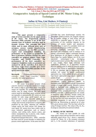
The rule editor window for the Fuzzy Controller for DC Motor is as shown in Fig.7.There are 25 rules in total
combining all the above rules
Fig. 7 Rule Editor Window for Fuzzy Controller of DC Motor
V FRACTIONAL ORDER PID
CONTROLLER
A. Fractional Calculus
To study the fractional order controllers,
the starting point is of course the fractional order
differential equations using fractional calculus.
Fractional calculus extends the classic concepts of
differential and integral calculus to an arbitrary
order. For the definition of the generalized operator
aD_t (where a and t are the limits and _ is the order
of the operation), the Riemann-Liouville (RL) and
the Gr ¨unwald-Letnikov (GL) definitions are
generally applied. The RL definition is given by (_
> 0): aD_
aDt
∝
f t =
1
Γ(n−1)
dn
dtn
f(Γ)
(t−Γ)α−n+1
t
a
dΓ
where 𝛤(x) is the gamma function of f(x)
The GL definition is (α∈ℝ) u
And [x] represents the integer part of x.
The classical PID controller can be generalized into
a fractional order PID controller, the so
called PIλ
Dμ
, whose integro-differential equation
can be expressed as:
u t = Kpe t +
1
TI
D−λ
e t + TDDμ
e(t) (3)
where KP is the proportional gain, TI is the integral
time constant, TD is the derivative time constant, 𝛌
is the (non-integer) order of the integrator and μ is
the (non-integer) order of the derivative action. The
corresponding transfer function is expressed as
C S =
U(S)
E(S)
= KP(1 +
1
TISλ + TASλ
) (4)
KI = KP /TI and KD = KP · TD, we obtain
C s = KP +
KI
Sλ + Kdsλ
(4.27)
It turns out in any case that in the
PIλ
Dμ
controller, there are five parameters to tune
and, most of all, the physical meaning of the two
additional parameters is not clear. Indeed, the effect
of changing these two parameters on the obtained
performance is not well understood.
B. Controller Scheme
The control scheme considered is shown
in Fig.8 where C and P are the controller and the
process transfer functions respectively, x is the
process output, y is the measured output, u is the
control variable, r is the reference signal and e =
r−y is the control error. Then, d denotes the load
disturbance signal and n denotes the measurement
noise signal. It is worth stressing that the
performance of the control system in general is
evaluated by considering all the input-output
relationships between the three inputs r, d and n,
and the three outputs y, x and u.
Fig. 8 Control scheme of FO PID
For the purpose of the description made in the
following sections, denote as S the sensitivity
function
S(s) =
1
1+C S P(S)
(5)
as T the complementary sensitivity function
T s =
C s P(s)
1+C s P(s)
(6)
and as L the open-loop transfer function
L(s) = C(s) P(s)
C. Design of FOPID Controller for Speed
Control of Dc Motor
Fig.9 shows the SIMULINK model for
speed control of separately excited dc motor using
FOPID Controller. Subsystem shows the model of
separately excited DC Motor as shown in Fig.1.
7. Safina Al Nisa, Lini Mathew, S Chatterji / International Journal of Engineering Research and
Applications (IJERA) ISSN: 2248-9622 www.ijera.com
Vol. 3, Issue 3, May-Jun 2013, pp.1137-1146
1143 | P a g e
Fig. 9 SIMULINK Model of Speed Control of
Motor using FOPID
To design a fractional controller, there are
two approaches possible. The first one is
placements of pole and second is by experimental
results. The method of experimental results is used
for design of controllers. The method involves
studying the closed loop response of system by
varying a tuning parameter. An appropriate value
of tuning parameter is chosen depending on the
closed loop performance requirements of the
system i.e. overshoot, settling time, rise time, etc.
Fractional PID controller design involves following
steps:
A. Determination of proportional gain KP:
The value of proportional gain KP is
adjusted to get minimum steady state error
possible. With increase in KP, the settling time
decreases but the steady state value remains
unchanged. A value of KP is chosen as:
KP = 221.59
B. Determination of KI and λ:
When integral time TI is increased keeping KP =
221.59, it is observed that the controlled response
become more and more oscillatory in nature. Now
KI is kept constant at 2.2375 x 10³
and integral
order λ is changed. The peak value and oscillatory
nature of the response increases with increasing
value of λ.. The integral order λ is chosen so as to
have less oscillation in the controlled response, less
settling time and KI is selected to have low possible
peak value.
The values chosen are:
λ = 0.87, KI = 2.2375 x 10³
C. Determination of KD and 𝛍:
The increase in derivative time KD causes the initial
response to set point change becomes faster and
also the peak value decreases. The value of
derivative order 𝛍 is varied, which affects the peak
value and also speed of the response. 𝛍 is chosen to
have faster response but to avoid any peak
overshoot. The values chosen for the derivative
gain and derivative order are:
KD = 2.4785, 𝛍 = 0.42
VI SIMULATION RESULTS
The speed vs time response of DC motor using PID
controller is shown in Fig.10.This output response
shows that there are initial oscillations in speed and
after a settling time of 4 seconds,the motor attains
the rated speed.
Fig. 10 SPEED VS TIME RESPONSE OF SPEED CONTROL OF DC MOTOR USING PID CONTROLLER
The speed vs time response of DC motor usingFuzzy- PID controller is shown in Fig.11. The model can be
simulated to visualize and analyse the result. This output response shows that after 2.7 seconds the motor attains
the rated speed of 157.07rad/s.
8. Safina Al Nisa, Lini Mathew, S Chatterji / International Journal of Engineering Research and
Applications (IJERA) ISSN: 2248-9622 www.ijera.com
Vol. 3, Issue 3, May-Jun 2013, pp.1137-1146
1144 | P a g e
Fig. 11 Speed VS Time Response of Fuzzy Tuned PID Controlled DC Motor
The speed vs time response of DC motor using FOPID controller is shown in Fig.12
Fig. 12 Simulation Results of Separately Excited DC Motor Using FOPID Controller
After analysing the above three graphs, the comparative table is made and results are analysed and discussed.
Table 7 shows the comparative analysis of the three controllers.
Table 7
The Comparative Analysis of the Controllers
The performance specifications of the controlled
system using the fractional controller are better
than that of the controlled system using classical
PID controller. In general, the system with the
integer order PID controllers takes more time to
settle than with fractional order PID controller.
Oscillations in FOPID are less as compared to
conventional PID. Settling time is less in FOPID as
compared to PID controller. When these two
controllers are compared with FLC, it is observed
that FLC is more efficient among the three
controllers.FLC parameter controller has less rising
and settling time as compared to other two
controllers. Steady state error is also less in Fuzzy
Logic Controller. FLC has better dynamic response
properties and steady-state properties.
VI CONCLUSION
In present work, performance comparison
of PID controller with that of fractional order PID
controller and Fuzzy Logic controller is presented.
Performance comparison are simulated and studied.
The time response characteristics of the three
systems are analysed. The effectiveness of the
fractional order PID controller and PID controller
and Fuzzy Logic controller is evaluated in terms of:
i. Rise-time
ii. Settling-time
iii. Steady state value
Comparing the step responses with the ones
obtained (in simulation) with the three controller,
Specifications PID FOPID FLC
Rise time 3sec 1sec 0.7sec
Settling time 4 sec 3sec 2.7sec
Steady state
value
156.3 156.5 157.07
9. Safina Al Nisa, Lini Mathew, S Chatterji / International Journal of Engineering Research and
Applications (IJERA) ISSN: 2248-9622 www.ijera.com
Vol. 3, Issue 3, May-Jun 2013, pp.1137-1146
1145 | P a g e
the better performance of the system with the
Fuzzy Logic controller was observed. Fractional
order PID controller for integer order plants offer
better flexibility in adjusting gain characteristics
than the PID controllers, owing to the two extra
tuning parameters i.e. order of integration and order
of derivative in addition to proportional gain,
integral time and derivative time. Fine-tuned Fuzzy
controller presents smaller overshoot and settling
time than conventional PID controller and FOPID
controller. The three parameters "KP", "KI", "KD"
of conventional PID control need to be constantly
adjusted in order to achieve better control
performance. In case of fractional PID five
parameters needs to be tuned to achieve better
performance. Fuzzy self-tuning PID parameters
controller can automatically adjust PID parameters
in accordance with the speed error and the rate of
speed error-change, so it has better self-adaptive
capacity. The reason for getting a smooth controller
output in the PID-like FLC case is because of the
fact that PID-like FLC updates the controller output
by making comparison of the error and the change
in error in angular displacement of the motor shaft.
REFRENCES
[1] Zhang G and Funji Furusho Fungi, “Speed
Control of Two-Inertia System by PI/PID
Control”, IEEE Transaction on Industrial
Electronics, Vo1. 47, pp. 603-609, June,
2000.
[2] I-Hai Lin P and Ellsworth Chris, “Design
and Implementation of a PC-Based
Universal Fuzzy Logic Controller
System”, Proceedings of International
IEEE/IAS Conference on Industrial
Automation and control, pp. 399-408, 06
August, 2002.
[3] Zadeh L.A., “Fuzzy Logic: Issues,
Contentions and Perspectives”, IEEE
International Conference on Acoustics,
Speech, and Signal Processing, VI, pp.
VI/183, Vol. 6, 19 April, 1994.
[4] Prommeuan S., Boonpiyathud S and
Suksri T, “Fuzzy Logic Based on
LabVIEW for Speed Control of Two-
Inertia System”, Proceedings of
International Joint Conference by the
Institute of Control, Robotics and Systems
(ICROS) and the Society of Instrument
and Control Engineers (SICE) on
Industrial Electronics, pp. 2867-2870,
August, 2009.
[5] Tipsuwan Y., Mo-Yuen Chow, “Fuzzy
logic Microcontroller Implementation for
DC Motor Speed Control”,
Proceedings of International IEEE
Conference on Industrial Electronic
Society, Vol. 3, pp. 1271-1276, 29
November, 1999.
[6] Sousa G.C.D and Bose B.K, “A Fuzzy Set
Theory Based Control of a Phase-
Controlled Converter DC Machine Drive”
IEEE Transaction on Industrial
Applications, Vol. 30, pp. 34-44, January,
1994.
[7] Katbab A., “Fuzzy Logic and Controller
Design-a Review”, Proceedings of IEEE
Conference on Visualize the Future, pp.
443-449, March, 1995.
[8] Wen J. Sheng Wang C. Hsu; Chang Y.
De; Teng C. Cheng., “Intelligent Control
of High-speed Sensorless Brushless DC
Motor for Intelligent Automobiles”,
Proceedings of IEEE Conference on
System, Man and Cybernetic, pp. 3394-
3398, October, 2008.
[9] N. Barakat., “Speed Control of a DC
Motor using a Feedforward Computed
Torque Control Scheme”, Proceedings of
IEEE Conference on Intelligent Control,
pp. 432-437, September, 1996.
[10] Khoei A., Hadidi Kh. and Yuvarajan S.,
“Fuzzy-Logic DC-Motor Controller with
Improved Performance”, Proceedings of
IEEE Conference on Industry
Applications, Vol. 3, pp. 1652-1656,
October, 1998.
[11] Altayef J. A. and Zhu Qun-xiong, “Real –
Time DC Motor Position Control by
(FPID) Controllers and Design (FLC)
Using LabVIEW Software Simulation”,
Proceedings of International Conference
on Computer and Automation Engineering
held in Singapur, Vol. 2, pp. 417-420, 26
February, 2010.
[12] Mrad F., DandachS H., Azar S.and Deeb
G., “Operator-Friendly Common Sense
Controller with Experimental Verification
using LabVIEW”, Proceedings of IEEE
International Symposium on Control and
Automation, pp. 1051-1055, June, 2005.
[13] Huibin Z., Jianxun Jin and Jun Cheng,
“Virtual Instrument Based Fuzzy Control,
System form PMLSM Drive” Proceedings
of IEEE International Conference on
Applied Superconductivity and
Electromagnetic Devices, pp. 299-303, 25
September, 2009.
[14] Khuntia S.R., Mohanty K.B., Panda S and
Ardil C, “A Comparative Study of P-I, I-
P, Fuzzy and Neuro-Fuzzy Controllers for
Speed Control of DC Motor Drive”,
Proceedings of International Journal on
Electrical and Computer Engineering, Vol.
5, pp. 287-291, 2010.
10. Safina Al Nisa, Lini Mathew, S Chatterji / International Journal of Engineering Research and
Applications (IJERA) ISSN: 2248-9622 www.ijera.com
Vol. 3, Issue 3, May-Jun 2013, pp.1137-1146
1146 | P a g e
[15] Natsheh E and K. A Buragga A.K.,
“Comparison between Conventional and
Fuzzy Logic PID Controllers for
Controlling DC Motors”, Proceedings of
International Journal on Computer Science
Issues, Vol.7, pp. 1694-0814, September,
2010.
[16] Zhao Chunna., Xue Dingy U and Chen
Y.Q., “A Fractional Order PID Tuning
Algorithm for A Class of Fractional Order
Plants” Proceedings of American Control
Conference, Minneapolis, pp. 3182-3187,
June, 2006.
[17] Kaur K., Chowdhury S. and Domijan A.,
“Fuzzy Logic Based Control of Variable
Speed Induction Machine Wind
Generation System", Proceedings of IEEE
Conference on Conversion and Delivery
of Electrical Energy, pp. 1-11, July, 2008.
[18] Ponce P., Ramirez F. and Medina V., “A
Novel Neuro-Fuzzy Controller Genetically
Enhanced Using LabVIEW”, Proceedings
of IEEE Annual Conference on Industrial
Electronics, pp. 1559-1565, 2008.
[19] Ismail A and Sharaf A.M., “An Efficient
Neuro Fuzzy Speed Controller for Large
Industrial DC Motor Drive”, Proceedings
of IEEE International Conference on
Control Application, Vol.2, pp. 1027-
1031, 10 December, 2002.
[20] Bimal B.K., “Expert System, Fuzzy Logic,
and Neural Network Applications in
Power Electronics and Motion Control”,
Proceedings of International journals, Vol.
82, pp. 1303-1323, August, 1994.
[21] Mountain J.R., “Fuzzy Logic Motor Speed
Control with Real-time Interface using an
8-bit Embedded Processor”, Proceedings
of IEEE Symposium on System Theory
(SSST), pp. 307-312, 7 March, 2010.
[22] Aceves Lopez A and Aguilar-Martin J, “A
Simplified Version of Mamdani's Fuzzy
Controller: the natural logic controller”,
Proceedings of IEEE International
Conference on Computational Intelligence
Society, Vol.14, pp. 16-30, 13 February,
2006.
[23] Pisoni E., Visioli. A and Dormido. S, “An
Interactive Tool for Fractional Order PID
Controllers”, Proceedings of IEEE
Annual Conference on Industrial
Electronics, held in Italy, pp. 1470-1475,
2009.
[24] Bingul. Z and Karahan. O, “Tuning of
Fractional PID Controllers using PSO
Algorithm for Robot Trajectory Control”
IEEE International Conference on
Mechatronics (ICM), pp. 955-960, 13
April, 2011.
[25] Yang Ding, Bin Sun, Yongmei Huang,
Weiwei Lin and Fei Qian, “Hybrid
MATLAB and LabVIEW to Implement an
Intelligent Foundation Field bus Control
System”, Proceedings on Intelligent
Control and Automation, pp. 4539-4543, 7
July, 2010.
[26] Sundaravadivu. K., B. Arun and
Saravanan K., “Design of Fractional Order
PID Controller for Liquid Level Control
of Spherical Tank”, Proceedings of IEEE
International Conference on Control
System, Computing and Engineering
(ICCSCE), pp. 291-295, 25 November,
2011.
[27] Hamamci S.E., “An Algorithm for
Stabilization of Fractional-Order Time
Delay Systems Using Fractional-Order
PID Controllers”, IEEE Transactions on
Automatic Control, Vol.52, pp. 1964–
1969, October, 2007.
[28] Wang. Z., Cao. G and Zhu. X., “Digital
Implementation of Fractional Order PID
Controller, and its Application”
Proceedings of Journal on Systems
Engineering and Electronics, Vol.16,
Issue.1, pp. 116-122, March, 2005.
[29] Zang. Y. “Fractional-order PID Controller
Tuning Based on Genetic Algorithm”
Proceedings of International Conference
on Business Management and Electronic
Information (BMEI), Vol.3, pp. 764-767,
13 May, 2011.