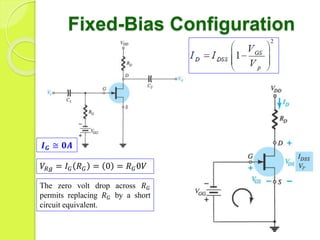
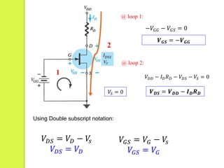
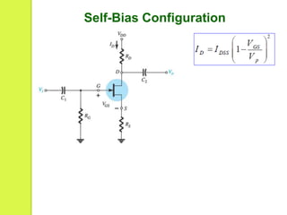
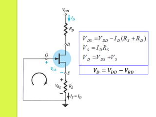
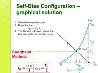
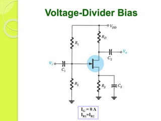
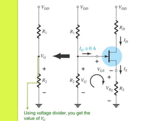
FET
Biasing
Engr. Jesus Rangcasajo
ECE 321 Instructor
jesusrangcasajo@gmail.com
Basic Current Relationships
Things to ponder!
Fixed-Bias Configuration
𝑰 𝑮 ≅ 𝟎𝑨
𝑉𝑅𝑔 = 𝐼 𝐺 𝑅 𝐺 = 0 = 𝑅 𝐺0𝑉
The zero volt drop across 𝑅 𝐺
permits replacing 𝑅 𝐺 by a short
circuit equivalent.
1
@ loop 1:
𝑽 𝑮𝑺 = −𝑽 𝑮𝑮
−𝑉𝐺𝐺 − 𝑉𝐺𝑆 = 0
2
@ loop 2:
𝑉𝐷𝐷 − 𝐼 𝐷 𝑅 𝐷 − 𝑉𝐷𝑆 − 𝑉𝑆 = 0
𝑽 𝑫𝑺 = 𝑽 𝑫𝑫 − 𝑰 𝑫 𝑹 𝑫𝑉𝑆 = 0
Using Double subscript notation:
𝑉𝐷𝑆 = 𝑉𝐷 − 𝑉𝑠
𝑉𝐷𝑆 = 𝑉𝐷
𝑉𝐺𝑆 = 𝑉𝐺 − 𝑉𝑠
𝑉𝐺𝑆 = 𝑉𝐺
For
Example: Find:
Self-Bias Configuration
1
@ loop 1:
−𝑉𝐺𝑆 − 𝑉𝑅𝑠 = 0
𝑽 𝑮𝑺 = −𝑽 𝑹𝒔 = −𝐼 𝐷 𝑅 𝑠
Note that the
current through 𝑅 𝑠
is the source
current, 𝐼𝑆
But
𝐼 𝐷 = 𝐼𝑆
𝑉𝑅𝑠 = 𝐼 𝐷 𝑅 𝑠
𝑉𝐷 = 𝑉𝐷𝐷 − 𝑉𝑅𝐷
Self-Bias Configuration –
graphical solution
1. Sketch the transfer curve
2. Draw the line
𝑽 𝑮𝑺= −𝐼 𝐷 𝑅 𝑠
3. The Q-point is located where the
line intersects the transfer curve.
Shorthand
Method:
𝐼 𝐷 =
𝐼 𝐷𝑆𝑆
4
𝑉𝐺𝑆 =
𝑉𝑝
2
Voltage-Divider Bias
Using voltage divider, you get the
value of 𝑉𝐺
For Example:
Source:
Electronic Devices and Circuit
Theory, 10th Ed., R. Boylestad &
L. Nashelsky, Copyright ©2009
by PEARSON Education, Inc.

Field Effect Transistor Biasing and Configuration