Download as PDF, PPTX
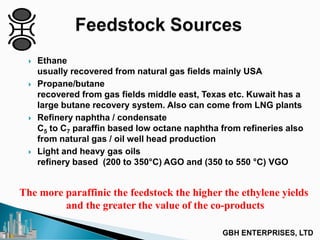

![Ethylene Selectivity :
% SC2H4 = 100 - % SC2H6 - % SC4+ - % SC6+
% SC2H6 is the ethane selectivity :
% SC2H6 = {[(C2H6)out –(C2H6)in]/[(C2H2)in-(C2H2)out ]}x 100
% SC4+ is the total C4 selectivity formed (i.e. Cis- and
trans-but-2-enes, but-1-ene and buta-1,3-diene), :
% SC4+ = {[2x(C4'sformed)]/[(C2H2)in-(C2H2)out]} x 100
(2 moles C2H2 1 mole C4’s)
% SC6+ is the total C6 selectivity formed,:
% SC6+ = {[3x(C6'sformed)]/ [(C2H2)in-(C2H2)out]} x 100
(3 moles C2H2 1 mole C6’s)
Important to ask customer his definition, many variations](https://image.slidesharecdn.com/ethyleneplantdesignconsiderations-130803103220-phpapp02/85/Ethylene-Plant-Design-Considerations-14-320.jpg)


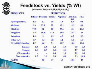
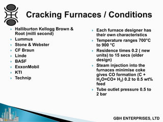
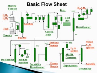
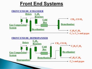
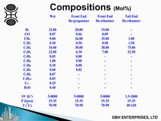
The document provides an in-depth overview of c2pt catalyst process technology, focusing on the design, operation, and various feedstocks such as ethane, propane-butane, and naphtha, primarily recovered from natural gas fields and refinery processes. It analyzes the importance of feedstock composition for maximizing ethylene yields and outlines the operational parameters and challenges of different furnace designs and catalysts used in the process. Additionally, the document discusses product separation and purification techniques that ensure high-quality output from the catalytic processes.


![Natural Gas to Olefins, Symposium[2]](https://cdn.slidesharecdn.com/ss_thumbnails/0b411131-d6a1-4822-ad58-dbcc1933154c-150612193624-lva1-app6891-thumbnail.jpg?width=640&height=640&fit=bounds)


![5G Explained! A High Level Overview [Introduction]](https://cdn.slidesharecdn.com/ss_thumbnails/5gexplainedahighleveloverview-260119165306-cc137a3e-thumbnail.jpg?width=640&height=640&fit=bounds)


