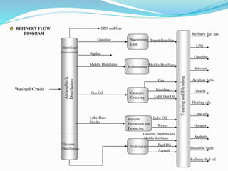
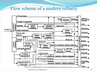
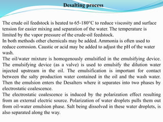
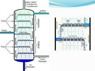
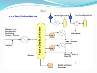
 After desalting and dehydration, crude is separated
into fractions by distillation.
 The distilled fractions cannot be used directly.
 The reason for such a complex set of processes is the
difference between the crude oil properties and the
needs of the market.
 Another reason for complexity is environmental.
Legislation demands cleaner products and is the major
drive for process improvement and development of
novel processes.
Physical
Chemical
Thermal Catalytic
Desalting/dehydration
Visbreaking
Hydrotreating (e.g.,
Hydrodesulfurization)
Distillation Delayed coking Catalytic reforming
Solvent extraction Flexicoking Catalytic cracking
Propane deasphalting Hydrocracking
Solvent dewaxing Catalytic dewaxing
Blending Alkylation
Polymerization
Isomerization
Typical Physical and Chemical processes in a
Petroleum Refinery
INDUSTRIAL PROCESSES IN THE PETROLEUM REFINING INDUSTRY
The process of oil refining involves five major processes which are briefly described:
SEPARATION PROCESSES
These processes involve separating
the different fractions of hydrocarbon
compounds that make up crude oil
base on their boiling point differences.
Additional processing of these
fractions is usually needed to produce
final products to be sold within the
market.
• Atmospheric distillation
• Vacuum distillation
• Light ends recovery (gas processing)
SEPARATION CONVERSION TREATING BLENDING AUXILIARY
ASSOCIATED OPERATIONS
SEPARATION CONVERSION TREATING BLENDING AUXILIARY
ASSOCIATED OPERATIONS
Include processes used to break down
large longer chain molecules into smaller
ones by heating using catalysts. change
the size and/or structure of hydrocarbon
molecules. These processes include:
Decomposition (dividing) by thermal and
catalytic cracking;
Unification (combining) through
alkylation and polymerization; and
Alteration (rearranging) with
isomerization and catalytic reforming.
• Cracking (thermal and catalytic)
• Reforming
• Alkylation
• Polymerization
• Isomerization
• Coking
• Visbreaking
CONVERSION PROCESSES
INDUSTRIAL PROCESSES IN THE PETROLEUM REFINING INDUSTRY
SEPARATION CONVERSION TREATING BLENDING AUXILIARY
ASSOCIATED OPERATIONS
TREATING PROCESSES
Petroleum-treating processes are used
to separate the undesirable
components and impurities such as
sulfur, nitrogen and heavy metals from
the products.
• Hydrodesulfurization
• Hydrotreating
• Chemical sweetening
• Acid gas removal
• Deasphalting
INDUSTRIAL PROCESSES IN THE PETROLEUM REFINING INDUSTRY
SEPARATION CONVERSION TREATING BLENDING AUXILIARY
ASSOCIATED OPERATIONS
BLENDING/COMBINATION PROCESSES
Is the process of mixing and combining
hydrocarbon fractions, additives, and other
components to produce finished products
with specific performance properties. Some
examples of this are lubricating oils, asphalt,
or gasoline with different octane ratings.
• Storage
• Blending
• Loading
• Unloading
INDUSTRIAL PROCESSES IN THE PETROLEUM REFINING INDUSTRY
SEPARATION CONVERSION TREATING BLENDING AUXILIARY
ASSOCIATED OPERATIONS
AUXILIARY PROCESSES
Processes that are vital to operations
by providing power, waste treatment
and other utility services. Products
from these facilities are usually
recycled and used in other processes
within the refinery and are also
important in regards to minimizing
water and air pollution.
• Boilers
• Waste water treatment
• Hydrogen production
• Sulfur recovery plant
INDUSTRIAL PROCESSES IN THE PETROLEUM REFINING INDUSTRY
Stabilizer
Vacuum
Distillation
Sweetening
Unit
Visbreaker
Hydrotreating
Catalytic
Cracking
Solvent
Extraction and
Dewaxing
LPH and Gas
Gasoline
Naphta
Middle Distillates
Gas Oil
Lube-Base
Stocks
Sweet Gasoline
Middle Distillates
Gas
Gasoline
Light Gas Oil
Lube Oil
Waxes
Gasoline, Naphtha and
Middle distillates
Fuel Oil
Asphalt
TreatingandBlending
Refinery fuel gas
Refinery fuel oil
Industrial fuels
Asphalts
Greases
Lube oils
Aviation fuels
Diesels
Heating oils
LPG
Gasoline
Solvents
Washed Crude
REFINERY FLOW
DIAGRAM
Flow scheme of a modern refinery
REFINING TECHNOLOGY 10
Desalting/dehydration
Crude oil often contains water, inorganic salts, suspended solids, and water
‐soluble trace metals.
• First step in the refining process is to remove these contaminants so as to
reduce corrosion, plugging, and fouling of equipment and to prevent poisoning
catalysts in processing units.
• The two most typical methods of crude ‐oil desalting are chemical and
electrostatic separation, and both use hot water as the extraction agent.
• In chemical desalting, water and chemical surfactant (demulsifiers) are added
to the crude, which is heated so that salts and other impurities dissolve or attach
to the water, then held in a tank to settle out.
• Electrical desalting is the application of high ‐voltage electrostatic charges to
concentrate suspended water globules in the bottom of the settling tank.
Surfactants are added only when the crude has a large amount of suspended
solids.
• A third (and rare) process filters hot crude using diatomaceous earth.
The crude oil feedstock is heated to 65‐180°C to reduce viscosity and surface
tension for easier mixing and separation of the water. The temperature is
limited by the vapor pressure of the crude‐oil feedstock.
In both methods other chemicals may be added. Ammonia is often used to
reduce corrosion. Caustic or acid may be added to adjust the pH of the water
wash.
The oil/water mixture is homogenously emulsified in the emulsifying device.
The emulsifying device (as a valve) is used to emulsify the dilution water
injected upstream in the oil. The emulsification is important for contact
between the salty production water contained in the oil and the wash water.
Then the emulsion enters the Desalters where it separates into two phases by
electrostatic coalescence.
The electrostatic coalescence is induced by the polarization effect resulting
from an external electric source. Polarization of water droplets pulls them out
from oil-water emulsion phase. Salt being dissolved in these water droplets, is
also separated along the way.
Desalting process
Crude Desalting (typical operating conditions)
oAPI Water Wash,
vol%
Temp. oF (oC)
>40 3-4 240-260 (115-125)
30-40 4-7 260-280 (125-140)
<30 7-10 280-330 (140-150)
Crude Distillation Unit
Crude Desalting
 Depending on the amount of salt in
crudes, several stages are required
in the desalting process (e.g. if the
amount of salt is greater than 20 lb
salt/1000 bbl (expressed as NaCl),
two-stage desalting is required)
Crude Desalting
 In order to promote the separation, a high-potential electrical field is
applied across the settling vessel to coalesce the droplets of salty
water more rapidly (electrostatic precipitator).
 Either AC or DC fields may be used and potentials from 12,000 –
35,000 volts are used to promote coalescence.
 For single-stage desalting units 90-95% efficiencies are obtained and
two-stage processes achieve 99% or better efficiency.
Distillation Column
Distillation is defined as: – a process in which a liquid or vapour mixture of
two or more substances is separated into its component fractions of desired
purity, by the application and removal of heat.
Distillation columns are classified by the manner in which they are operated:
1. Batch, in which the feed to the column is introduced batch‐wise. That is,
the column is charged with a 'batch' and then the distillation process is
carried out. When the desired task is achieved, a next batch of feed is
introduced.
2. Continuous columns process a continuous feed stream. No interruptions
occur unless there is a problem with the column or surrounding process
units. They are capable of handling high throughputs and are the most
common of the two types.
Continuous distillation columns
Classified according to:
1. Nature of the feed that they are processing:
– binary column ‐ feed contains only two components;
– multi‐component column ‐ feed contains more than two components.
2. Number of product streams they have:
– multi‐product column ‐ column has more than two product streams.
3. Where extra feed exits when used to help with the separation:
– extractive distillation ‐ where the extra feed appears in the bottom
product stream;
– azeotropic distillation ‐ where the extra feed appears at the top product
stream.
4. Type of column internals:
– tray column ‐ trays of various designs used to hold up the liquid to provide
better contact between vapour and liquid;
– packed column ‐ packings are used to enhance vapour‐liquid contact.
Main Components of Distillation Columns
• A vertical shell where separation of
liquid components is done.
• Column internals e.g. trays/plates
and/or packings which are used to
enhance component separations.
• A reboiler to provide the necessary
vaporization for the distillation process.
• A condenser to cool and condense the
vapour leaving the top of the column.
• A reflux drum to hold the condensed
vapour from the top of the column so
that liquid (reflux) can be recycled back
to the column.
Trays and plates
Bubble cap trays
A riser or chimney is fitted
over each hole, and a cap
covers the riser. The cap is
mounted with a space to
allow vapour to rise through
the chimney and be directed
downward by the cap, finally
discharging through slots in
the cap, and bubbling through
the liquid on the tray.
Valve trays
Perforations are covered by caps lifted by vapour,
which creates a flow area and directs the vapour
horizontally into the liquid.
Sieve trays
Sieve trays are simply metal plates with holes in
them. Vapour passes straight upward through the
liquid on the plate. The arrangement, number and
size of the holes are design parameters.
Packings
 Packings are passive devices designed to increase the interfacial
area for vapour-liquid contact.
 They do not cause excessive pressure-drop across a packed
section, which is important because a high pressure drop would
mean that more energy is required to drive the vapour up the
distillation column.
 Packed columns are called continuous-contact columns while
trayed columns are called staged-contact columns because of the
manner in which vapour and liquid are contacted.
Basic operation
 The feed is introduced somewhere near
the middle of the column to a tray known
as the feed tray.
 The feed tray divides the column into a
top (enriching or rectification) and a
bottom (stripping) section.
 The feed flows down the column where
it is collected in the reboiler.
 Heat (usually as steam) is supplied to the
reboiler to generate vapour.
 The vapour from the reboiler is re-
introduced into the unit at the bottom of
the column.
 The liquid removed from the reboiler is
known as the bottoms product or simply,
bottoms.
• Vapour moves up the column, exits the top, and is cooled in a condenser. The
condensed liquid is stored in a holding vessel known as the reflux drum. Some
of this liquid is recycled back to the top of the column and this is called the
reflux. The condensed liquid that is removed from the system is known as the
distillate or top product.
• Thus, there are internal flows of vapour and liquid within the column as well
as external flows of feeds and product streams, into and out of the column.
Pumpback and pumparound
 Reflux is provided by condensing the tower
overhead vapors and returning a portion of
the liquid to the top of the tower, and also
by pump-around and pumpback streams
lower in the tower.
 Each of the sidestreams products removed
from the tower decreases the amount of
reflux below the point of drawoff.
 If maximum reflux and fractionation is
obtained by removing all the heat at the top
of the tower, this will result in an inverted
cone-type liquid loading, which requires a
very large diameter at the top of the tower.
 To reduce the top diameter of the tower and
to provide uniform liquid loading over the
length of the tower, pumpback and
pumparound is introduced to the tower
operation.
Pumpback and pumparound
 In pumpback or pumparound,
liquid is removed from the
tower, cooled by a heat
exchanger, and returned to
the tower.
 Alternatively, a portion of the
cooled sidestream may be
returned to the tower.
 This cold stream condenses
more of the vapors coming
from the lower tower section
and thereby increases the
reflux below that point.
Sidestripping columns
 The liquid sidestream withdrawn from the
tower will contain low-boiling
components which lower the flashpoint
(because the lighter products pass through
the heavier products and are in
equilibrium on every tray).
 These light ends are stripped from each
sidestream in a separate small stripping
tower containing four to ten trays with
steam introduced under the bottom tray.
 The steam and stripped light ends are
vented back into the vapor zone of the
main column above the corresponding
side-draw tray.
Tower bottom
 Although crude towers do not
normally use reboilers, several
trays are generally incorporated
below the flash zone.
 Steam is introduced below the
bottom tray to strip any
remaining gas oil from the liquid
in the flash zone and to produce
a high flash-point bottoms.
 Moreover, the steam reduces the
partial pressure of the
hydrocarbons and thus lowers
the required vaporization
temperature.
Crude Distillation Unit (CDU)
Process Description (CDU)
 Crude oil is pumped from the storage to be heated by exchange
against hot overhead and product side streams in the Crude
Unit.
 At a preheat temperature of about 200-250 °F (93-121oC),
water is injected into the crude to dissolve salt that is usually
present.
 The mixture enters a desalter drum to remove salt water.
 The crude oil leaves the desalter drum and enters a surge drum.
Some of the light ends and any entrained water are flashed off
and routed directly to the distillation tower flash zone (they do
not pass through to the heater).
 On leaving the remaining heat exchanger train after the surge
drum, the crude oil is heated in a fired heater to cause
vaporization of all products withdrawn above the flash zone
plus 10-20% of the bottom product (overflash).
Process Description (CDU)
 The desalted crude feedstock is preheated using recovered process heat. The
feedstock then flows to a direct‐fired crude charge heater then into the vertical
distillation column just above the bottom, at pressures slightly above atmospheric
and at temperatures ranging from 340‐400°C (above these temperatures undesirable
thermal cracking may occur). All but the heaviest fractions flash into vapor.
 The unvaporized portion of the crude leaves the bottom of the tower via a steam
stripper section.
 Distillate products are removed from the selected trays (draw-off trays) in this
sections of the tower (steam stripped and sent to storage).
 The full naphtha vapor is allowed to leave the top of the tower to be condensed and
collected in the overhead drum. A portion of this stream is returned to the tower as
reflux.
 The side stream distillates:
 Heavy gas oil (has the highest boiling point)
 Light gas oil (will be come Diesel)
 Kerosene (will become Jet Fuel)
 Atmospheric column with pre flash
Vacuum distillation
• To further distill the residuum or topped crude from the atmospheric
tower without thermal cracking, reduced pressure is required.
• The process takes place in one or more vacuum distillation towers.
• The principles of vacuum distillation resemble those of fractional
distillation except that larger diameter columns are used to maintain
comparable vapor velocities at the reduced pressures. The internal designs
of some vacuum towers are different from atmospheric towers in that
random packing and demister pads are used instead of trays.
• A typical first‐phase vacuum tower may produce gas oils, lubricating‐
oil base stocks, and heavy residual for propane deasphalting.
• A second‐phase tower operating at lower vacuum may distill surplus
residuum from the atmospheric tower, which is not used for lube‐stock
processing, and surplus residuum from the first vacuum tower not used for
deasphalting.
• Vacuum towers are typically used to separate catalytic cracking feedstock
from surplus residuum.
 Simplified flow scheme of an oil refinery with possible
locations of desulphurization units
Desulphurization Process
Hydrodesulfurization (HDS) is a catalytic chemical process widely used to
remove sulfur (S) from natural gas and from refined petroleum products, such as
gasoline or petrol, jet fuel, kerosene, diesel fuel, and fuel oil. The purpose of removing
the sulfur is to reduce the sulfur dioxide (SO2) emissions that result from using those
fuels in automotive vehicles, aircraft, railroad locomotives, ships, gas or oil burning
power plants, residential and industrial furnaces, and other forms of fuel combustion.
Another important reason for removing sulfur from the naphtha streams within a
petroleum refinery is that sulfur, even in extremely low concentrations, poisons the
noble metal catalysts (platinum and rhenium) in the catalytic reforming units that are
subsequently used to upgrade the octane rating of the naphtha streams.
The industrial hydrodesulfurization processes include facilities for the capture and
removal of the resulting hydrogen sulfide (H2S) gas. In petroleum refineries, the
hydrogen sulfide gas is then subsequently converted into byproduct elemental sulfur
or sulfuric acid (H2SO4).
An HDS unit in the petroleum refining industry is also often referred to as a
hydrotreater.
 Hydrogenation is a class of chemical reactions in which the net result is the
addition of hydrogen (H). Hydrogenolysis is a type of hydrogenation and
results in the cleavage of the C-X chemical bond, where C is a carbon atom
and X is a sulfur (S), nitrogen (N) or oxygen (O) atom. The net result of a
hydrogenolysis reaction is the formation of C-H and H-X chemical bonds.
Thus, hydrodesulfurization is a hydrogenolysis reaction. Using ethanethiol
(C2H5SH), a sulfur compound present in some petroleum products, as an
example, the hydrodesulfurization reaction can be simply expressed as:
 Ethanethiol + Hydrogen → Ethane + Hydrogen sulfide
C2H5SH + H2 → C2H6 + H2S
Process description
 In an industrial hydrodesulfurization unit, such as in a refinery, the
hydrodesulfurization reaction takes place in a fixed-bed reactor at elevated
temperatures ranging from 300 to 400 °C and elevated pressures ranging
from 30 to 130 atmospheres of absolute pressure, typically in the presence
of a catalyst consisting of an alumina base impregnated with cobalt and
molybdenum, CoMo/Al2O3 (usually called a CoMo catalyst). Occasionally,
a combination of nickel and molybdenum, NiMo/Al2O3(called NiMo) is
used, in addition to the CoMo catalyst, for specific difficult-to-treat feed
stocks, such as those containing a high level of chemically bound nitrogen.
 The image below is a schematic depiction of the equipment and the process
flow streams in a typical refinery HDS unit.
Hydrodesulfurization Plant
 The liquid feed (at the bottom left in the diagram) is pumped up to the
required elevated pressure and is joined by a stream of hydrogen-rich recycle
gas. The resulting liquid-gas mixture is preheated by flowing through a heat
exchanger. The preheated feed then flows through a fired heater where the
feed mixture is totally vaporized and heated to the required elevated
temperature before entering the reactor and flowing through a fixed-bed of
catalyst where the hydrodesulfurization reaction takes place.
 The hot reaction products are partially cooled by flowing through the heat
exchanger where the reactor feed was preheated and then flows through a
water-cooled heat exchanger before it flows through the pressure controller
(PC) and undergoes a pressure reduction down to about 3 to 5 atmospheres.
The resulting mixture of liquid and gas enters the gas separator vessel at about
35 °C and 3 to 5 atmospheres of absolute pressure.
 Most of the hydrogen-rich gas from the gas separator vessel is
recycle gas, which is routed through an amine contactor for removal
of the reaction product H2S that it contains. The H2S-free hydrogen-
rich gas is then recycled back for reuse in the reactor section. Any
excess gas from the gas separator vessel joins the sour gas from the
stripping of the reaction product liquid.
 The liquid from the gas separator vessel is routed through a reboiled
stripper distillation tower. The bottoms product from the stripper is
the final desulfurized liquid product from hydrodesulfurization unit.
 The overhead sour gas from the stripper contains hydrogen, methane,
ethane, hydrogen sulfide, propane, and, perhaps, some butane and
heavier components. That sour gas is sent to the refinery's central gas
processing plant for removal of the hydrogen sulfide in the refinery's
main amine gas treating unit and through a series of distillation towers
for recovery of propane, butane and pentane or heavier components.
The residual hydrogen, methane, ethane, and some propane is used as
refinery fuel gas. The hydrogen sulfide removed and recovered by the
amine gas treating unit is subsequently converted to elemental sulfur in
a Claus process unit or to sulfuric acid in a wet sulfuric acid process or
in the conventional Contact Process.

Chapter 2 crude_oil_processing2

  • 2.
     After desaltingand dehydration, crude is separated into fractions by distillation.  The distilled fractions cannot be used directly.  The reason for such a complex set of processes is the difference between the crude oil properties and the needs of the market.  Another reason for complexity is environmental. Legislation demands cleaner products and is the major drive for process improvement and development of novel processes.
  • 3.
    Physical Chemical Thermal Catalytic Desalting/dehydration Visbreaking Hydrotreating (e.g., Hydrodesulfurization) DistillationDelayed coking Catalytic reforming Solvent extraction Flexicoking Catalytic cracking Propane deasphalting Hydrocracking Solvent dewaxing Catalytic dewaxing Blending Alkylation Polymerization Isomerization Typical Physical and Chemical processes in a Petroleum Refinery
  • 4.
    INDUSTRIAL PROCESSES INTHE PETROLEUM REFINING INDUSTRY The process of oil refining involves five major processes which are briefly described: SEPARATION PROCESSES These processes involve separating the different fractions of hydrocarbon compounds that make up crude oil base on their boiling point differences. Additional processing of these fractions is usually needed to produce final products to be sold within the market. • Atmospheric distillation • Vacuum distillation • Light ends recovery (gas processing) SEPARATION CONVERSION TREATING BLENDING AUXILIARY ASSOCIATED OPERATIONS
  • 5.
    SEPARATION CONVERSION TREATINGBLENDING AUXILIARY ASSOCIATED OPERATIONS Include processes used to break down large longer chain molecules into smaller ones by heating using catalysts. change the size and/or structure of hydrocarbon molecules. These processes include: Decomposition (dividing) by thermal and catalytic cracking; Unification (combining) through alkylation and polymerization; and Alteration (rearranging) with isomerization and catalytic reforming. • Cracking (thermal and catalytic) • Reforming • Alkylation • Polymerization • Isomerization • Coking • Visbreaking CONVERSION PROCESSES INDUSTRIAL PROCESSES IN THE PETROLEUM REFINING INDUSTRY
  • 6.
    SEPARATION CONVERSION TREATINGBLENDING AUXILIARY ASSOCIATED OPERATIONS TREATING PROCESSES Petroleum-treating processes are used to separate the undesirable components and impurities such as sulfur, nitrogen and heavy metals from the products. • Hydrodesulfurization • Hydrotreating • Chemical sweetening • Acid gas removal • Deasphalting INDUSTRIAL PROCESSES IN THE PETROLEUM REFINING INDUSTRY
  • 7.
    SEPARATION CONVERSION TREATINGBLENDING AUXILIARY ASSOCIATED OPERATIONS BLENDING/COMBINATION PROCESSES Is the process of mixing and combining hydrocarbon fractions, additives, and other components to produce finished products with specific performance properties. Some examples of this are lubricating oils, asphalt, or gasoline with different octane ratings. • Storage • Blending • Loading • Unloading INDUSTRIAL PROCESSES IN THE PETROLEUM REFINING INDUSTRY
  • 8.
    SEPARATION CONVERSION TREATINGBLENDING AUXILIARY ASSOCIATED OPERATIONS AUXILIARY PROCESSES Processes that are vital to operations by providing power, waste treatment and other utility services. Products from these facilities are usually recycled and used in other processes within the refinery and are also important in regards to minimizing water and air pollution. • Boilers • Waste water treatment • Hydrogen production • Sulfur recovery plant INDUSTRIAL PROCESSES IN THE PETROLEUM REFINING INDUSTRY
  • 9.
    Stabilizer Vacuum Distillation Sweetening Unit Visbreaker Hydrotreating Catalytic Cracking Solvent Extraction and Dewaxing LPH andGas Gasoline Naphta Middle Distillates Gas Oil Lube-Base Stocks Sweet Gasoline Middle Distillates Gas Gasoline Light Gas Oil Lube Oil Waxes Gasoline, Naphtha and Middle distillates Fuel Oil Asphalt TreatingandBlending Refinery fuel gas Refinery fuel oil Industrial fuels Asphalts Greases Lube oils Aviation fuels Diesels Heating oils LPG Gasoline Solvents Washed Crude REFINERY FLOW DIAGRAM
  • 10.
    Flow scheme ofa modern refinery REFINING TECHNOLOGY 10
  • 11.
    Desalting/dehydration Crude oil oftencontains water, inorganic salts, suspended solids, and water ‐soluble trace metals. • First step in the refining process is to remove these contaminants so as to reduce corrosion, plugging, and fouling of equipment and to prevent poisoning catalysts in processing units. • The two most typical methods of crude ‐oil desalting are chemical and electrostatic separation, and both use hot water as the extraction agent. • In chemical desalting, water and chemical surfactant (demulsifiers) are added to the crude, which is heated so that salts and other impurities dissolve or attach to the water, then held in a tank to settle out. • Electrical desalting is the application of high ‐voltage electrostatic charges to concentrate suspended water globules in the bottom of the settling tank. Surfactants are added only when the crude has a large amount of suspended solids. • A third (and rare) process filters hot crude using diatomaceous earth.
  • 12.
    The crude oilfeedstock is heated to 65‐180°C to reduce viscosity and surface tension for easier mixing and separation of the water. The temperature is limited by the vapor pressure of the crude‐oil feedstock. In both methods other chemicals may be added. Ammonia is often used to reduce corrosion. Caustic or acid may be added to adjust the pH of the water wash. The oil/water mixture is homogenously emulsified in the emulsifying device. The emulsifying device (as a valve) is used to emulsify the dilution water injected upstream in the oil. The emulsification is important for contact between the salty production water contained in the oil and the wash water. Then the emulsion enters the Desalters where it separates into two phases by electrostatic coalescence. The electrostatic coalescence is induced by the polarization effect resulting from an external electric source. Polarization of water droplets pulls them out from oil-water emulsion phase. Salt being dissolved in these water droplets, is also separated along the way. Desalting process
  • 13.
    Crude Desalting (typicaloperating conditions) oAPI Water Wash, vol% Temp. oF (oC) >40 3-4 240-260 (115-125) 30-40 4-7 260-280 (125-140) <30 7-10 280-330 (140-150)
  • 15.
  • 16.
    Crude Desalting  Dependingon the amount of salt in crudes, several stages are required in the desalting process (e.g. if the amount of salt is greater than 20 lb salt/1000 bbl (expressed as NaCl), two-stage desalting is required)
  • 17.
    Crude Desalting  Inorder to promote the separation, a high-potential electrical field is applied across the settling vessel to coalesce the droplets of salty water more rapidly (electrostatic precipitator).  Either AC or DC fields may be used and potentials from 12,000 – 35,000 volts are used to promote coalescence.  For single-stage desalting units 90-95% efficiencies are obtained and two-stage processes achieve 99% or better efficiency.
  • 18.
    Distillation Column Distillation isdefined as: – a process in which a liquid or vapour mixture of two or more substances is separated into its component fractions of desired purity, by the application and removal of heat. Distillation columns are classified by the manner in which they are operated: 1. Batch, in which the feed to the column is introduced batch‐wise. That is, the column is charged with a 'batch' and then the distillation process is carried out. When the desired task is achieved, a next batch of feed is introduced. 2. Continuous columns process a continuous feed stream. No interruptions occur unless there is a problem with the column or surrounding process units. They are capable of handling high throughputs and are the most common of the two types.
  • 19.
    Continuous distillation columns Classifiedaccording to: 1. Nature of the feed that they are processing: – binary column ‐ feed contains only two components; – multi‐component column ‐ feed contains more than two components. 2. Number of product streams they have: – multi‐product column ‐ column has more than two product streams. 3. Where extra feed exits when used to help with the separation: – extractive distillation ‐ where the extra feed appears in the bottom product stream; – azeotropic distillation ‐ where the extra feed appears at the top product stream. 4. Type of column internals: – tray column ‐ trays of various designs used to hold up the liquid to provide better contact between vapour and liquid; – packed column ‐ packings are used to enhance vapour‐liquid contact.
  • 20.
    Main Components ofDistillation Columns • A vertical shell where separation of liquid components is done. • Column internals e.g. trays/plates and/or packings which are used to enhance component separations. • A reboiler to provide the necessary vaporization for the distillation process. • A condenser to cool and condense the vapour leaving the top of the column. • A reflux drum to hold the condensed vapour from the top of the column so that liquid (reflux) can be recycled back to the column.
  • 21.
    Trays and plates Bubblecap trays A riser or chimney is fitted over each hole, and a cap covers the riser. The cap is mounted with a space to allow vapour to rise through the chimney and be directed downward by the cap, finally discharging through slots in the cap, and bubbling through the liquid on the tray.
  • 22.
    Valve trays Perforations arecovered by caps lifted by vapour, which creates a flow area and directs the vapour horizontally into the liquid.
  • 23.
    Sieve trays Sieve traysare simply metal plates with holes in them. Vapour passes straight upward through the liquid on the plate. The arrangement, number and size of the holes are design parameters.
  • 24.
    Packings  Packings arepassive devices designed to increase the interfacial area for vapour-liquid contact.  They do not cause excessive pressure-drop across a packed section, which is important because a high pressure drop would mean that more energy is required to drive the vapour up the distillation column.  Packed columns are called continuous-contact columns while trayed columns are called staged-contact columns because of the manner in which vapour and liquid are contacted.
  • 27.
    Basic operation  Thefeed is introduced somewhere near the middle of the column to a tray known as the feed tray.  The feed tray divides the column into a top (enriching or rectification) and a bottom (stripping) section.  The feed flows down the column where it is collected in the reboiler.  Heat (usually as steam) is supplied to the reboiler to generate vapour.  The vapour from the reboiler is re- introduced into the unit at the bottom of the column.  The liquid removed from the reboiler is known as the bottoms product or simply, bottoms.
  • 28.
    • Vapour movesup the column, exits the top, and is cooled in a condenser. The condensed liquid is stored in a holding vessel known as the reflux drum. Some of this liquid is recycled back to the top of the column and this is called the reflux. The condensed liquid that is removed from the system is known as the distillate or top product. • Thus, there are internal flows of vapour and liquid within the column as well as external flows of feeds and product streams, into and out of the column.
  • 29.
    Pumpback and pumparound Reflux is provided by condensing the tower overhead vapors and returning a portion of the liquid to the top of the tower, and also by pump-around and pumpback streams lower in the tower.  Each of the sidestreams products removed from the tower decreases the amount of reflux below the point of drawoff.  If maximum reflux and fractionation is obtained by removing all the heat at the top of the tower, this will result in an inverted cone-type liquid loading, which requires a very large diameter at the top of the tower.  To reduce the top diameter of the tower and to provide uniform liquid loading over the length of the tower, pumpback and pumparound is introduced to the tower operation.
  • 30.
    Pumpback and pumparound In pumpback or pumparound, liquid is removed from the tower, cooled by a heat exchanger, and returned to the tower.  Alternatively, a portion of the cooled sidestream may be returned to the tower.  This cold stream condenses more of the vapors coming from the lower tower section and thereby increases the reflux below that point.
  • 32.
    Sidestripping columns  Theliquid sidestream withdrawn from the tower will contain low-boiling components which lower the flashpoint (because the lighter products pass through the heavier products and are in equilibrium on every tray).  These light ends are stripped from each sidestream in a separate small stripping tower containing four to ten trays with steam introduced under the bottom tray.  The steam and stripped light ends are vented back into the vapor zone of the main column above the corresponding side-draw tray.
  • 33.
    Tower bottom  Althoughcrude towers do not normally use reboilers, several trays are generally incorporated below the flash zone.  Steam is introduced below the bottom tray to strip any remaining gas oil from the liquid in the flash zone and to produce a high flash-point bottoms.  Moreover, the steam reduces the partial pressure of the hydrocarbons and thus lowers the required vaporization temperature.
  • 35.
  • 36.
    Process Description (CDU) Crude oil is pumped from the storage to be heated by exchange against hot overhead and product side streams in the Crude Unit.  At a preheat temperature of about 200-250 °F (93-121oC), water is injected into the crude to dissolve salt that is usually present.  The mixture enters a desalter drum to remove salt water.  The crude oil leaves the desalter drum and enters a surge drum. Some of the light ends and any entrained water are flashed off and routed directly to the distillation tower flash zone (they do not pass through to the heater).  On leaving the remaining heat exchanger train after the surge drum, the crude oil is heated in a fired heater to cause vaporization of all products withdrawn above the flash zone plus 10-20% of the bottom product (overflash).
  • 37.
    Process Description (CDU) The desalted crude feedstock is preheated using recovered process heat. The feedstock then flows to a direct‐fired crude charge heater then into the vertical distillation column just above the bottom, at pressures slightly above atmospheric and at temperatures ranging from 340‐400°C (above these temperatures undesirable thermal cracking may occur). All but the heaviest fractions flash into vapor.  The unvaporized portion of the crude leaves the bottom of the tower via a steam stripper section.  Distillate products are removed from the selected trays (draw-off trays) in this sections of the tower (steam stripped and sent to storage).  The full naphtha vapor is allowed to leave the top of the tower to be condensed and collected in the overhead drum. A portion of this stream is returned to the tower as reflux.  The side stream distillates:  Heavy gas oil (has the highest boiling point)  Light gas oil (will be come Diesel)  Kerosene (will become Jet Fuel)
  • 38.
     Atmospheric columnwith pre flash
  • 39.
    Vacuum distillation • Tofurther distill the residuum or topped crude from the atmospheric tower without thermal cracking, reduced pressure is required. • The process takes place in one or more vacuum distillation towers. • The principles of vacuum distillation resemble those of fractional distillation except that larger diameter columns are used to maintain comparable vapor velocities at the reduced pressures. The internal designs of some vacuum towers are different from atmospheric towers in that random packing and demister pads are used instead of trays. • A typical first‐phase vacuum tower may produce gas oils, lubricating‐ oil base stocks, and heavy residual for propane deasphalting. • A second‐phase tower operating at lower vacuum may distill surplus residuum from the atmospheric tower, which is not used for lube‐stock processing, and surplus residuum from the first vacuum tower not used for deasphalting. • Vacuum towers are typically used to separate catalytic cracking feedstock from surplus residuum.
  • 42.
     Simplified flowscheme of an oil refinery with possible locations of desulphurization units Desulphurization Process
  • 43.
    Hydrodesulfurization (HDS) isa catalytic chemical process widely used to remove sulfur (S) from natural gas and from refined petroleum products, such as gasoline or petrol, jet fuel, kerosene, diesel fuel, and fuel oil. The purpose of removing the sulfur is to reduce the sulfur dioxide (SO2) emissions that result from using those fuels in automotive vehicles, aircraft, railroad locomotives, ships, gas or oil burning power plants, residential and industrial furnaces, and other forms of fuel combustion. Another important reason for removing sulfur from the naphtha streams within a petroleum refinery is that sulfur, even in extremely low concentrations, poisons the noble metal catalysts (platinum and rhenium) in the catalytic reforming units that are subsequently used to upgrade the octane rating of the naphtha streams. The industrial hydrodesulfurization processes include facilities for the capture and removal of the resulting hydrogen sulfide (H2S) gas. In petroleum refineries, the hydrogen sulfide gas is then subsequently converted into byproduct elemental sulfur or sulfuric acid (H2SO4). An HDS unit in the petroleum refining industry is also often referred to as a hydrotreater.
  • 44.
     Hydrogenation isa class of chemical reactions in which the net result is the addition of hydrogen (H). Hydrogenolysis is a type of hydrogenation and results in the cleavage of the C-X chemical bond, where C is a carbon atom and X is a sulfur (S), nitrogen (N) or oxygen (O) atom. The net result of a hydrogenolysis reaction is the formation of C-H and H-X chemical bonds. Thus, hydrodesulfurization is a hydrogenolysis reaction. Using ethanethiol (C2H5SH), a sulfur compound present in some petroleum products, as an example, the hydrodesulfurization reaction can be simply expressed as:  Ethanethiol + Hydrogen → Ethane + Hydrogen sulfide C2H5SH + H2 → C2H6 + H2S
  • 45.
    Process description  Inan industrial hydrodesulfurization unit, such as in a refinery, the hydrodesulfurization reaction takes place in a fixed-bed reactor at elevated temperatures ranging from 300 to 400 °C and elevated pressures ranging from 30 to 130 atmospheres of absolute pressure, typically in the presence of a catalyst consisting of an alumina base impregnated with cobalt and molybdenum, CoMo/Al2O3 (usually called a CoMo catalyst). Occasionally, a combination of nickel and molybdenum, NiMo/Al2O3(called NiMo) is used, in addition to the CoMo catalyst, for specific difficult-to-treat feed stocks, such as those containing a high level of chemically bound nitrogen.  The image below is a schematic depiction of the equipment and the process flow streams in a typical refinery HDS unit.
  • 46.
  • 47.
     The liquidfeed (at the bottom left in the diagram) is pumped up to the required elevated pressure and is joined by a stream of hydrogen-rich recycle gas. The resulting liquid-gas mixture is preheated by flowing through a heat exchanger. The preheated feed then flows through a fired heater where the feed mixture is totally vaporized and heated to the required elevated temperature before entering the reactor and flowing through a fixed-bed of catalyst where the hydrodesulfurization reaction takes place.  The hot reaction products are partially cooled by flowing through the heat exchanger where the reactor feed was preheated and then flows through a water-cooled heat exchanger before it flows through the pressure controller (PC) and undergoes a pressure reduction down to about 3 to 5 atmospheres. The resulting mixture of liquid and gas enters the gas separator vessel at about 35 °C and 3 to 5 atmospheres of absolute pressure.
  • 48.
     Most ofthe hydrogen-rich gas from the gas separator vessel is recycle gas, which is routed through an amine contactor for removal of the reaction product H2S that it contains. The H2S-free hydrogen- rich gas is then recycled back for reuse in the reactor section. Any excess gas from the gas separator vessel joins the sour gas from the stripping of the reaction product liquid.  The liquid from the gas separator vessel is routed through a reboiled stripper distillation tower. The bottoms product from the stripper is the final desulfurized liquid product from hydrodesulfurization unit.
  • 49.
     The overheadsour gas from the stripper contains hydrogen, methane, ethane, hydrogen sulfide, propane, and, perhaps, some butane and heavier components. That sour gas is sent to the refinery's central gas processing plant for removal of the hydrogen sulfide in the refinery's main amine gas treating unit and through a series of distillation towers for recovery of propane, butane and pentane or heavier components. The residual hydrogen, methane, ethane, and some propane is used as refinery fuel gas. The hydrogen sulfide removed and recovered by the amine gas treating unit is subsequently converted to elemental sulfur in a Claus process unit or to sulfuric acid in a wet sulfuric acid process or in the conventional Contact Process.