Download to read offline
![Akanksha Yadav Int. Journal of Engineering Research and Applications www.ijera.com
ISSN : 2248-9622, Vol. 4, Issue 11(Version - 6), November 2014, pp.37-41
www.ijera.com 37 | P a g e
High Speed Memory Efficient Multiplier-less 1-D 9/7 Wavelet Filters Based NEDA Technique Akanksha Yadav1, Anushree2
Hindustan College Of Science & Technology Farah Mathura (India) ABSTRACT— Conventional distributed arithmetic (DA) is popular in field programmable gate array (FPGA) design, and it features on-chip ROM to achieve high speed and regularity. In this paper, we describe high speed area efficient 1-D discrete wavelet transform (DWT) using 9/7 filter based new efficient distributed arithmetic (NEDA) Technique. Being area efficient architecture free of ROM, multiplication, and subtraction, NEDA can also expose the redundancy existing in the adder array consisting of entries of 0 and 1. This architecture supports any size of image pixel value and any level of decomposition. The parallel structure has 100% hardware utilization efficiency.
Keywords: - 1-D Discrete Wavelet Transform (DWT), NEDA, Low Pass Filter, High Pass Filter, Xilinx Simulation.
I. INTRODUCTION
The well-known image coding standards, namely, MPEG-4 and JPEG2000 have adopted 1-D DWT as the transform coder due to its remarkable advantages over the other transforms. For lossy and lossless compression, Daubechies 9/7 orthogonal filter is used as the default wavelet filter in JPEG 2000. Efficient implementation of 1-D DWT using 9/7 filters in resource-constrained hand-held devices with capability for real-time processing of the computation-intensive multimedia applications is, therefore, a necessary challenge. Multiplier-less hardware implementation approach provides a kind of solution to this problem due to its scope for lower hardware-complexity and higher throughput of computation. Several parallel and pipeline systems that meet the computational requirements of the discrete wavelet transform have been proposed. Some of them need multiprocessor to implement it and the system is complex, time consuming, and costly [1]. The Field programmable gate array (FPGA) provides us a new way to digital signal processing [2]. Several designs have been proposed for the multiplier, multiplier-less implementation of 1-D DWT based on the principle of multiplier based design (MBD) distributed arithmetic (DA) canonic signed digit (CSD), [1]–[3]. The structure of distributes the bits of the fixed coefficients instead of the bits of input samples. Consequently, the adder- complexity of the structure of depends on the DA- matrix of the fixed coefficients [2]. Canonic signed digit (CSD) are popular for representing a number with fewest number of non- zero digit. The CSD representation of a number
contains the minimum possible number of nonzero bits, thus the name canonic. The CSD representation of a number is unique and CSD numbers cover the range (-4/3, 4/3), out of which the value in the range {-1, 1} are of greatest interest. Martina et al [5] have approximated the 9/7 filter coefficients and performance of a hardware implementation of the 9/7 filter bank depends on the accuracy of coefficients representation. By that approach, they have significantly reduced the adder- complexity of the 9/7 DWT. Gourav et al [7] have suggested an LUT-less DA-based design for the implementation of 1-D DWT. They have eliminated the ROM cells required by the DA-based structures at the cost of additional adders and multiplexors. Some of them need Rom to implement it and the system is complex, time consuming, and costly [4] The adder-complexity of this structure is significantly higher than the other multiplier-less structures. In this paper, we have proposed an efficient scheme to derive NEDA-based bit-parallel structures, for low- hardware and high-speed computation DWT using 9/7 filters [4]. The remainder of the paper is organized as follows: New efficient distributed arithmetic based computation of 1-D DWT using 9/7 filter is presented in Section II. The proposed structures are presented in Section III. Hardware and time complexity of the proposed structures are discussed and compared with the existing structures in Section IV. Conclusion is presented in Section V.
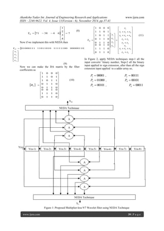
II. NEW EFFICIENT DISTRIBUTED ARITHMETRIC (NEDA) Let us consider the following sum of products [4]:
RESEARCH ARTICLE OPEN ACCESS](https://image.slidesharecdn.com/f0411063741-141212224706-conversion-gate01/85/High-Speed-Memory-Efficient-Multiplier-less-1-D-9-7-Wavelet-Filters-Based-NEDA-Technique-1-320.jpg)
![Akanksha Yadav Int. Journal of Engineering Research and Applications www.ijera.com
ISSN : 2248-9622, Vol. 4, Issue 11(Version - 6), November 2014, pp.37-41
www.ijera.com 38 | P a g e
k
L
k
k Y X R 1
(1)
Where k X are fixed coefficients and they k Y are the
input data words. Equation (1) can be expressed in
the form of a matrix product as:
L
L
Y
Y
Y
R X X X
.
... 2
1
1 2
(2)
Both k X and k Y are in two’s complement format.
The two’s complement representation of k X may be
expressed as
1
2 2
M
i N
i i
k
M M
k k X X X (3)
Where i
k X 0 or 1, and i N, N+1… M
and
M
k X is the sign bit and
N
k X is the least significant
bit (LSB).
Equation (3) can be expressed in matrix form as:
M
k
N
k
N
k
N N M
k
X
X
X
X
.
2 2 ... 2
1
1
(4)
Similarly k Y can be represented in two’s
complemented format as:
1
2 2
X
i W
i i
k
X X
k k Y Y Y (5)
Where i
k Y 0 or 1, and i W, W+1, …,X
and
M
k Y is the sign bit and
N
k Y is the least significant
bit (LSB).
Now on combining equations (1) and (3), we get-
1
( .2 ) ( .2 )
M
i N
M M i i R R R (6)
Where
L
k
k
i
k
i R X Y
1
, i N, N+1… M
III. PROPOSED ARCHITECTURE
In this paper, we have proposed a high speed
area efficient multiplier-less 1-D 9/7 wavelet filters
based NEDA technique. 9/7 wavelet filters
coefficient i.e. 9 low-pass and 7 high-pass wavelet
filters coefficient are given in table1. We multiply the
filter coefficients by 128 for simplification. The
mathematical calculation for 1-D high pass filter
output is explained by an example.
Table 1: Show high-pass and low-pass wavelet filters
coefficient.
Wavelet filters
coefficients
Multiplied
by 128
8 bit binary
representation
with 2’s
complement
of negative no.
0 h 0.60294901823 77 01001101
1 h 0.26686441184 34 00100010
2 h -0.07822326652 -10 11110110
3 h -0.01686411844 -2 11111110
4 h 0.026748757410 3 00000011
0 g 0.55754352622 71 01000111
1 g -0.29563588155 -38 01011010
2 g -0.02877176311 -4 11111100
3 g 0.045635881557 6 00000110
Where 0 h , 1 h , 2 h , 3 h , 4 h are the Low pass filter
coefficients and 0 g , 1 g , 2 g , 3 g are the High pass
filter coefficients.
If we take the high pass coefficients 0 g , 1 g , 2 g and
3 g multiply by 1 r , 2 r , 3 r and 4 r then we get the High
pass output H Y of the 9/7 filter as [6]:
4
3
2
1
0 1 2 3
r
r
r
r
Y g g g g H (7)
Where
( ) ( 6) 1 r Y n Y n
( 1) ( 5) 2 r Y n Y n
( 2) ( 4) 3 r Y n Y n
( 3) 4 r Y n
Let 1 r =1, 2 r =2, 3 r =3, 4 r =4 then](https://image.slidesharecdn.com/f0411063741-141212224706-conversion-gate01/85/High-Speed-Memory-Efficient-Multiplier-less-1-D-9-7-Wavelet-Filters-Based-NEDA-Technique-2-320.jpg)
![Akanksha Yadav Int. Journal of Engineering Research and Applications www.ijera.com
ISSN : 2248-9622, Vol. 4, Issue 11(Version - 6), November 2014, pp.37-41
www.ijera.com 41 | P a g e
= 1 1011 + 1000000000111 Total output YP (7) = 000000000111 = 7 Carry is rejected.
IV. SIMULATION RESULT
The proposed architecture has very low hardware complexity compared to DA based structures, because DA requires ROM.In the proposed architecture, calculate the high-pass and low-pass wavelet filter output using NEDA scheme. NEDA does not require ROM. Proposed structure consist only 33 adders, zero mux and 29 registers. In the proposed architecture is better than other architecture in shown the Table 2. Table 2: Comparison of proposed with existing architectures Arch.: Architecture, MUL: Multiplier MUX: Multiplex, REG: Register, CP: Cyclic Period
Arch.
MUL
Adder
MUX
Rom
REG
CP
Alam et al. [2]
0
43
9
4
8
12 TA
Martina et al [5]
0
36
5
4
8
9 TA
Martina et al. [6]
0
36
4
4
8
6 TA
Gaurav et al. [7]
0
30
1
4
8
6 TA
Proposed
0
30
1
0
8
6 TA
V. CONCLUSION We propose a novel distributed arithmetic paradigm named NEDA for VLSI implementation of digital signal processing (DSP) algorithms involving inner product of vectors and vector-matrix multiplication. Mathematical proof is given for the validity of the NEDA scheme. We demonstrate that NEDA is a very efficient architecture with adders as the main component and free of ROM (free memory), multiplication, and subtraction. For the adder array, a systematic approach is introduced to remove the potential redundancy so that minimum additions are necessary. NEDA is an accuracy preserving scheme and capable of maintaining a satisfactory performance even at low DA precision. REFERENCES
[1] S.G. Mallat, ―A Theory for Multiresolution Signal Decomposition: The Wavelet Representation‖, IEEE Trans. on Pattern
Analysis on Machine Intelligence, 110. July1989, pp. 674-693.
[2] M. Alam, C. A. Rahman, and G. Jullian, ‖Efficient distributed arithmetic based DWT architectures for multimedia applications,‖ in Proc. IEEE Workshop on SoC for real-time applications, pp. 333 336, 2003.
[3] X. Cao, Q. Xie, C. Peng, Q. Wang and D. Yu, ‖An efficient VLSI implementation of distributed architecture for DWT,‖ in Proc. IEEE Workshop on Multimedia and Signal Process., pp. 364-367, 2006.
[4] Archana Chidanandan and Magdy Bayoumi, “AREA-EFFICIENT NEDA ARCHITECTURE FOR THE 1-D DCT/IDCT,‖ ICASSP 2006.
[5] M. Martina, and G. Masera, ‖Low- complexity, efficient 9/7 wavelet filters VLSI implementation,‖ IEEE Trans. on Circuits and Syst. II, Express Brief vol. 53, no. 11, pp. 1289-1293, Nov. 2006.
[6] M. Martina, and G. Masera, ‖Multiplierless, folded 9/7-5/3 wavelet VLSI architecture,‖ IEEE Trans. on Circuits and syst. II, Express Brief vol. 54, no. 9, pp. 770-774, Sep. 2007.
[7] Gaurav Tewari, Santu Sardar, K. A. Babu, ‖ High-Speed & Memory Efficient 2-D DWT on Xilinx Spartan3A DSP using scalable Polyphase Structure with DA for JPEG2000 Standard,‖ 978-1-4244-8679-3/11/$26.00 ©2011 IEEE.
[8] B. K. Mohanty and P. K. Meher, ―Memory Efficient Modular VLSI Architecture for Highthroughput and Low-Latency Implementation of Multilevel Lifting 2-D DWT‖, IEEE TRANSACTIONS ON SIGNAL PROCESSING, VOL. 59, NO. 5, MAY 2011.
[9] B. K. Mohanty and P. K. Meher, ―Memory- Efficient High-Speed Convolution-based Generic Structure for Multilevel 2-D DWT‖, IEEE TRANSACTIONS ON CIRCUITS SYSTEMS FOR VIDEO TECHNOLOGY.
[10] B. K. Mohanty and P. K. Meher, ―Efficient Multiplierless Designs for 1-D DWT using 9/7 Filters Based on Distributed Arithmetic‖, ISIC 2009.](https://image.slidesharecdn.com/f0411063741-141212224706-conversion-gate01/85/High-Speed-Memory-Efficient-Multiplier-less-1-D-9-7-Wavelet-Filters-Based-NEDA-Technique-5-320.jpg)

This document proposes a new efficient distributed arithmetic (NEDA) technique for implementing high-speed memory-efficient 1-D 9/7 wavelet filters. NEDA is an area-efficient architecture that does not require ROM, multiplication, or subtraction. It can expose redundancy in adder arrays consisting of entries of 0 and 1. The document describes how NEDA can be used to compute the high pass filter output of a 1-D discrete wavelet transform using 9/7 filters through an example. It also shows the proposed NEDA architecture and processing steps to obtain the low pass and high pass filter outputs with just additions and shifts.