Download to read offline
![International Research Journal of Engineering and Technology (IRJET) e-ISSN: 2395-0056
Volume: 07 Issue: 02 | Feb 2020 www.irjet.net p-ISSN: 2395-0072
© 2020, IRJET | Impact Factor value: 7.34 | ISO 9001:2008 Certified Journal | Page 3018
DISTRIBUTED ARITHMETIC METHOD FOR COMPLEX MULTIPLICATION
C.V. Thejashwini1, Dr. A. Sumathi2
1P.G Student, Department of Electronics and communication Engineering, Adhiyamaan College of Engineering,
Tamilnadu, India
2Professor, Department of Electronics and communication Engineering, Adhiyamaan College of Engineering,
Tamilnadu, India
---------------------------------------------------------------------***---------------------------------------------------------------------
Abstract –In today’s technology, delay, power and area are
the crucial parameters to outline any kind of the algorithmon
FPGA. FFT plays a vital role in acquiring the signal
characteristics with the least use of carrying out parameters.
Speed multipliers are fundamental parts of DSP systems.
Multipliers are complex process and consumes more time. In
order to lower the complexity multiplication, various
multiplier less method are introduced. Weplannedanefficient
DA based complex multiplier inplace of regular multiplier.
Coding is done using Verilog language. Using Xilinx 14.5i tool
with Spartan 6 kit, Simulation can be achieved.
Key Words: FFT, DA algorithm, SDF, complex multiplier.
1. INTRODUCTION
Currently, FFT has got the great prominence in the fields of
biomedical applications and communication to analyze the
signal features. The conversion of original domain in to a
frequency domain signal called FFT. To make full use of
hardware resources, algorithm of FFT is exposed. This FFT
algorithm plays a important role in the communication field.
Arithmeticoperationswithcomplex numbersarerequiredin
many DSP algorithms, e.g. FFT. The complex multiplication
operation is upscale and the most superior factor in
computing the speed. If both the inputs are variables, better
to use regular multiplier architecture. In case, one of the
input is constant i.e. twiddle factors, so we use DA based
multiplication. This can be proven that it is faster than
conventional multiplier. Figure 1 shows the basic
multiplication technique. Each black dot be regarded as a
single digit.
Fig -1: Basic multiplication
1.1 RADIX-2 FFT ALGORITHM
Cooley and Tukey presented thefirstFFTalgorithm,whichis
Radix-2 algorithm. The DFT of a given resultant X[n] can be
estimated using the formula.
1
0
( ) ( )
N
nk
N
n
X k x n W
(1)
Where Wn is twiddle factor.
1( ) (2 )mX r X (2)
2 ( ) (2 1)mX r X
Then, the N-point DFT becomes
1 1
( ) 0 ( ) 0
( ) ( ) ( )
N N
nk nk
N N
n even n odd
X K x n W x n W
( /2) 1 ( /2) 1
0 0
1(2 ) 2(2 1)
N N
nk nk nk
N N N
m m
x m W W x m W
Properties of twiddle factors are used. They are symmetry
and periodicity.
1 2[ ] ( ) ( )k
NX k X k W X k
1 2[ / 2] ( ). ( )k
NX k N X k W X k (3)
Fig -2: Basic butterfly unit.
The above figure 2 shows the basic butterfly structure.
1.2 RADIX-2 SDF
SDF FFT architecture has the most efficient utilization
memory for pipelined FFT processor. The first half data
input is saved in memory. So, the delayed input processed](https://image.slidesharecdn.com/irjet-v7i2648-201128045754/85/IRJET-Distributed-Arithmetic-Method-for-Complex-Multiplication-1-320.jpg)
![International Research Journal of Engineering and Technology (IRJET) e-ISSN: 2395-0056
Volume: 07 Issue: 02 | Feb 2020 www.irjet.net p-ISSN: 2395-0072
© 2020, IRJET | Impact Factor value: 7.34 | ISO 9001:2008 Certified Journal | Page 3018
DISTRIBUTED ARITHMETIC METHOD FOR COMPLEX MULTIPLICATION
C.V. Thejashwini1, Dr. A. Sumathi2
1P.G Student, Department of Electronics and communication Engineering, Adhiyamaan College of Engineering,
Tamilnadu, India
2Professor, Department of Electronics and communication Engineering, Adhiyamaan College of Engineering,
Tamilnadu, India
---------------------------------------------------------------------***---------------------------------------------------------------------
Abstract –In today’s technology, delay, power and area are
the crucial parameters to outline any kind of the algorithmon
FPGA. FFT plays a vital role in acquiring the signal
characteristics with the least use of carrying out parameters.
Speed multipliers are fundamental parts of DSP systems.
Multipliers are complex process and consumes more time. In
order to lower the complexity multiplication, various
multiplier less method are introduced. Weplannedanefficient
DA based complex multiplier inplace of regular multiplier.
Coding is done using Verilog language. Using Xilinx 14.5i tool
with Spartan 6 kit, Simulation can be achieved.
Key Words: FFT, DA algorithm, SDF, complex multiplier.
1. INTRODUCTION
Currently, FFT has got the great prominence in the fields of
biomedical applications and communication to analyze the
signal features. The conversion of original domain in to a
frequency domain signal called FFT. To make full use of
hardware resources, algorithm of FFT is exposed. This FFT
algorithm plays a important role in the communication field.
Arithmeticoperationswithcomplex numbersarerequiredin
many DSP algorithms, e.g. FFT. The complex multiplication
operation is upscale and the most superior factor in
computing the speed. If both the inputs are variables, better
to use regular multiplier architecture. In case, one of the
input is constant i.e. twiddle factors, so we use DA based
multiplication. This can be proven that it is faster than
conventional multiplier. Figure 1 shows the basic
multiplication technique. Each black dot be regarded as a
single digit.
Fig -1: Basic multiplication
1.1 RADIX-2 FFT ALGORITHM
Cooley and Tukey presented thefirstFFTalgorithm,whichis
Radix-2 algorithm. The DFT of a given resultant X[n] can be
estimated using the formula.
1
0
( ) ( )
N
nk
N
n
X k x n W
(1)
Where Wn is twiddle factor.
1( ) (2 )mX r X (2)
2 ( ) (2 1)mX r X
Then, the N-point DFT becomes
1 1
( ) 0 ( ) 0
( ) ( ) ( )
N N
nk nk
N N
n even n odd
X K x n W x n W
( /2) 1 ( /2) 1
0 0
1(2 ) 2(2 1)
N N
nk nk nk
N N N
m m
x m W W x m W
Properties of twiddle factors are used. They are symmetry
and periodicity.
1 2[ ] ( ) ( )k
NX k X k W X k
1 2[ / 2] ( ). ( )k
NX k N X k W X k (3)
Fig -2: Basic butterfly unit.
The above figure 2 shows the basic butterfly structure.
1.2 RADIX-2 SDF
SDF FFT architecture has the most efficient utilization
memory for pipelined FFT processor. The first half data
input is saved in memory. So, the delayed input processed](https://image.slidesharecdn.com/irjet-v7i2648-201128045754/75/IRJET-Distributed-Arithmetic-Method-for-Complex-Multiplication-1-2048.jpg)
![International Research Journal of Engineering and Technology (IRJET) e-ISSN: 2395-0056
Volume: 07 Issue: 02 | Feb 2020 www.irjet.net p-ISSN: 2395-0072
© 2020, IRJET | Impact Factor value: 7.34 | ISO 9001:2008 Certified Journal | Page 3019
with the remaining input in butterfly unit. The output data
fed back to input of butterfly unit through buffer for further
processing.
SDF has a great advantage that it requires less memory
space. Especially for applications like low power design,this
SDF offers several advantage. This is the reason SDF is
adopted. SDF block reduces the complex adder by 50% and
also produce the output in normal order. The utilization of
multiplier remains 50%. The SDF block is used to share
delay elements between butterfly inputs and outputs to
improve efficiency of hardware. The figure 3 describes the
SDF architecture.
Fig -3: Radix-2 SDF architecture
2. RELATED WORK
Kavitha. M .V et.al [1] Radix-8 booth multiplier will be
implemented as a complex multiplier for inplace FFT
architecture. This multiplier operates in parallel and
requires less adders. Using this multiplier, power is reduced
and time requirement also very less. To diminish power
dissipation and area, CSLA is used. Overall delay, area and
power consumption will be minimized in the proposed
method with the support of CSLA adder.
Laguri, Nisha et.al [2] has introduced an efficient split-radix
FFT based on DA. To reduce the multipliers, DA isused. With
the Radix-split FFT, few number of additions and
multiplications were achieved but itintroducestheoverflow
issue.
Anumol B .Chennattucherry et.al [3] in this paperstatedthat
FIR Filter developed with DA is phenomenal of all regular
multipliers. The multiply and accumulate operation is
translated in to shift and add operation When this
Distributed Arithmetic algorithm is directly applied to
realize FIR Filter. Due to this, speed is optimized. Pipeline
architecture can achieve a low latencyanda highthroughput
which are suitable for real time applications. In pipelineFFT
architecture, we made use of SDC. This SDF pipeline FFT
architecture is exceptional because it requires less memory
space. Especially for the application like DSP or low power
design, SDF has a great advantage. SDF is selectedduetothis
reasons.
P.Sritha et.al [4] this paper has presented several DA based
filter techniques. But modified DA technique has requires
only lower area. Various DA technique proven that these
techniques were effective in reduction of area requirement.
3. COMPLEX MULTIPLIER
The complex multiplication is a very expensive operation, to
minimize the multiplicative complexity of the twiddle factor
inside of the butterfly unit by calculating the only real
multiplications, additions, and subtractions.
The twiddle factor multiplication,
A+ j B = (Y+ j Z) (C+ j S) (1)
The complex multiplications can be simplified as
A=(C-S) Y+X (2)
B=(C+S) Z-X (3)
Where X=C(Y-Z). S, C are preempted and stored in a
memory. C+S, C-S and C are the three coefficients. Figure 4
shows the signal flow graph.
Fig -4: Signal flow graph
A complex multiplier consists of 2 regular adder and 4
regular multiplier. Instead of using the actual multiplier and
adder blocks, we introduce a multiplier and adder less
complex multiplier using the concept of Distributed
Arithmetic (DA). Figure 5 represents the complex multiplier
which is shown below.
Fig -5: Complex Multiplier](https://image.slidesharecdn.com/irjet-v7i2648-201128045754/85/IRJET-Distributed-Arithmetic-Method-for-Complex-Multiplication-2-320.jpg)
![International Research Journal of Engineering and Technology (IRJET) e-ISSN: 2395-0056
Volume: 07 Issue: 02 | Feb 2020 www.irjet.net p-ISSN: 2395-0072
© 2020, IRJET | Impact Factor value: 7.34 | ISO 9001:2008 Certified Journal | Page 3021
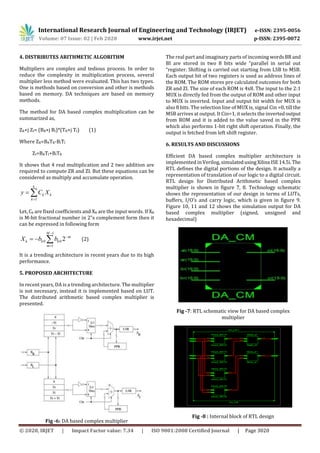
Fig -9: Technology schematic view for DA based complex
multiplier
Fig -10: Simulation output for DA based complex
multiplier(signed number)
Fig -11: Simulation output for DA based complex
multiplier(unsigned number)
Fig -12: Simulation output for DA based complex
multiplier(hexadecimal)
Table 1 shows the performance comparison of multipliers. .
It is clear from the Table I that the LUTs is less than regular
mutiplier. The total number of LUTs and delay is reduced.
Table -I: Comparison of Multipliers
MULTIPLIER TYPE NO.OF.L
UTs
DELAY(ns)
WALLACE MULTIPLIER 43 15.195
BOOTH MULTIPLIER 35 12.783
PROPOSED DISTRIBUTED
ARITHMETIC BASED
COMPLEX MULTIPLIER
26 11.249
7. CONCLUSION
In this paper, distributed arithmetic based complex
multiplier has been proposed. Parameters like area and
delay are considered for performance evaluation needed by
the SDF FFT. DA based complex multiplierhasbeenusedasa
complex multiplier for proposed model. The replacement of
booth multiplication, Wallace multiplier with DA based
complex multiplier offers great advantage. This shows that
our proposed system reducestheoverall area anddelaythan
conventional multipliers.Theproposedarchitecturecan also
be adapted to high point FFT applications with lowersizeoff
twiddle factor ROM’s. DA based multipliers are used in FIR
filters.
REFERENCES
[1] S,Ranjitha, S.G.Hiremath, Kavitha M.V, Suresh H.N,”A
Novel RTL Architecture for FPGA Implementationof32-
point FFT for High Speed Applications” IOSR-
JCE,ISSN:2278-0661, Volume 19, Issue 2, Ver.II(Mar
2017).](https://image.slidesharecdn.com/irjet-v7i2648-201128045754/85/IRJET-Distributed-Arithmetic-Method-for-Complex-Multiplication-4-320.jpg)
![International Research Journal of Engineering and Technology (IRJET) e-ISSN: 2395-0056
Volume: 07 Issue: 02 | Feb 2020 www.irjet.net p-ISSN: 2395-0072
© 2020, IRJET | Impact Factor value: 7.34 | ISO 9001:2008 Certified Journal | Page 3022
[2] Laguri, visha and K,Bahnusudha, “DA based VLSI radix-
split FFT ”ICGCCEE, International Conference, pp:1-
5,IEEE,2014.
[3] Anumol B. Chennattucherry, Diego James” A Novel
Approach to lessen power and area for FFT
Implemention”, IJAREEIE, ISSN: 2278-8875. Vol. 2,
Special issue 1, Dec 2013.
[4] P. Srinivas, M.Suhasini “performance estimation and
design of multiplier with DA algorithm”, ISSN: 2231-
0371, Vol.3, Issue- 4, 2012.](https://image.slidesharecdn.com/irjet-v7i2648-201128045754/85/IRJET-Distributed-Arithmetic-Method-for-Complex-Multiplication-5-320.jpg)

This document describes a distributed arithmetic method for complex multiplication that reduces complexity compared to a regular multiplier. It presents a distributed arithmetic based complex multiplier architecture that uses lookup tables instead of actual multipliers and adders. The architecture stores pre-calculated outcomes for the real and imaginary parts of the complex multiplication in ROMs. It shifts the inputs and uses the output bits as addresses for the ROMs to perform the multiplication with less components than a traditional design. The proposed architecture is implemented in Verilog and simulated using Xilinx tools to verify its functionality for signed, unsigned and hexadecimal numbers.