Download to read offline
![IOSR Journal of VLSI and Signal Processing (IOSR-JVSP)
ISSN: 2319 – 4200, ISBN No. : 2319 – 4197 Volume 1, Issue 4 (Nov. - Dec. 2012), PP 37-41
www.iosrjournals.org
www.iosrjournals.org 37 | Page
Performance analysis of High Speed ADC using SR F/F
Ajay Vishwakarma, Sweta Sahu, Vijay Vishwakarma , Richa Soni
(School Of Electronics Engineering[SENSE],VLSI Division, VIT University, India)
Abstract: This paper present a new design of comparator for flash ADC . The flash ADC is the fastest
Application ADC that requires the high speed comparator. The new design consist of sense amplifier and SR
Latch ,the combining configuration of design have the considerable stable output which helps in high speed
and resolution. The use of SR symmetric latch makes stable output as compared to the conventional SR latch
moreover the design has high resolution. This paper has been done in 180 nm and 90nm gpdk in CADENCE
VIRTUOSO. For low power application. There are many issues in the design of the comparator, we will discuss
those design issues in this paper.
I. Introduction
The design of comparator is the most critical part in the flash ADC, since the speed and the resolution
is determined by the comparator. The dual tail current sense amplifier based comparator can run faster with
lower supply voltage than the normal one, and the kick back effect is also better than the normal one. The
symmetric S-R latch provides shorter delay time and stable time than the normal S-R latch. Combing the sense
amplifier based comparator and the symmetric S-R latch, the whole block can run faster and the output signal is
more stable than the normal structure. This design of comparator is for 2GSample/sec flash ADC. Based on
IEEE 802.15.3a WPAN UWB applications, the signals using multi-band orthogonal frequency division
multiplexing (MB-OFDM) occupy a bandwidth of 528MHz for every band. It requires the conversion rate at
least higher than 1.06GSample/sec.
1.1. The Analysis Of The Traditional Sense Amplifier Based Comparator And Sr Latch:
In the analysis of any comparator there are 2 stages in which operation is divided, one is reset phase
and other is regeneration phase. In this sense amplifier based comparator sense amplifier connects positive
feedback with the resistive input as shown in fig.1.Now during reset phase when clock is low, the nodes of
inverters (M1-M4) are charged to Vdd, through transistor M7 and M8. Again on regeneration phase when clock
is high Nmos transistor M9 is turned on which is a part of differential pair M5 and M6. Current flowing through
this pair controls the latch circuit and small changes between differential pair cause large output change. And
this differential pair discharge the node Ni, and later difference of the input voltage will built charge it. When Ni
come to Vth voltage then inverter M1,M3 turns on and this wil start the positive feedback. After Ni comes to
2Vth below Vdd transistor M2,M4 are turn on. Now with the help of strong positive feedback small input
converted to full differential output.
For the generation of output there is very short period of time in sense amplifier when its gain is
good.so switch M11 ,M12 is added to increase the integration time. In the conventional sense amplifier, it is
better to add a reset switch (M11, M12) connecting the Vdd and the Di so as to increase the integration time . In
the sense amplifier there is only a very short time in which the differential pair actually have the gain. Actually
the differential pair comes to triode region during Ni drop to Vth. This reset transistor also increase the active
time of differential pair and decrease the offset effect in coming signals.
Fig.1: Conventional Sense Amplifier Based Comparator](https://image.slidesharecdn.com/f0143741-140511234832-phpapp02/85/Performance-analysis-of-High-Speed-ADC-using-SR-F-F-1-320.jpg)
![IOSR Journal of VLSI and Signal Processing (IOSR-JVSP)
ISSN: 2319 – 4200, ISBN No. : 2319 – 4197 Volume 1, Issue 4 (Nov. - Dec. 2012), PP 37-41
www.iosrjournals.org
www.iosrjournals.org 37 | Page
Performance analysis of High Speed ADC using SR F/F
Ajay Vishwakarma, Sweta Sahu, Vijay Vishwakarma , Richa Soni
(School Of Electronics Engineering[SENSE],VLSI Division, VIT University, India)
Abstract: This paper present a new design of comparator for flash ADC . The flash ADC is the fastest
Application ADC that requires the high speed comparator. The new design consist of sense amplifier and SR
Latch ,the combining configuration of design have the considerable stable output which helps in high speed
and resolution. The use of SR symmetric latch makes stable output as compared to the conventional SR latch
moreover the design has high resolution. This paper has been done in 180 nm and 90nm gpdk in CADENCE
VIRTUOSO. For low power application. There are many issues in the design of the comparator, we will discuss
those design issues in this paper.
I. Introduction
The design of comparator is the most critical part in the flash ADC, since the speed and the resolution
is determined by the comparator. The dual tail current sense amplifier based comparator can run faster with
lower supply voltage than the normal one, and the kick back effect is also better than the normal one. The
symmetric S-R latch provides shorter delay time and stable time than the normal S-R latch. Combing the sense
amplifier based comparator and the symmetric S-R latch, the whole block can run faster and the output signal is
more stable than the normal structure. This design of comparator is for 2GSample/sec flash ADC. Based on
IEEE 802.15.3a WPAN UWB applications, the signals using multi-band orthogonal frequency division
multiplexing (MB-OFDM) occupy a bandwidth of 528MHz for every band. It requires the conversion rate at
least higher than 1.06GSample/sec.
1.1. The Analysis Of The Traditional Sense Amplifier Based Comparator And Sr Latch:
In the analysis of any comparator there are 2 stages in which operation is divided, one is reset phase
and other is regeneration phase. In this sense amplifier based comparator sense amplifier connects positive
feedback with the resistive input as shown in fig.1.Now during reset phase when clock is low, the nodes of
inverters (M1-M4) are charged to Vdd, through transistor M7 and M8. Again on regeneration phase when clock
is high Nmos transistor M9 is turned on which is a part of differential pair M5 and M6. Current flowing through
this pair controls the latch circuit and small changes between differential pair cause large output change. And
this differential pair discharge the node Ni, and later difference of the input voltage will built charge it. When Ni
come to Vth voltage then inverter M1,M3 turns on and this wil start the positive feedback. After Ni comes to
2Vth below Vdd transistor M2,M4 are turn on. Now with the help of strong positive feedback small input
converted to full differential output.
For the generation of output there is very short period of time in sense amplifier when its gain is
good.so switch M11 ,M12 is added to increase the integration time. In the conventional sense amplifier, it is
better to add a reset switch (M11, M12) connecting the Vdd and the Di so as to increase the integration time . In
the sense amplifier there is only a very short time in which the differential pair actually have the gain. Actually
the differential pair comes to triode region during Ni drop to Vth. This reset transistor also increase the active
time of differential pair and decrease the offset effect in coming signals.
Fig.1: Conventional Sense Amplifier Based Comparator](https://image.slidesharecdn.com/f0143741-140511234832-phpapp02/75/Performance-analysis-of-High-Speed-ADC-using-SR-F-F-1-2048.jpg)
![Performance analysis of High Speed ADC using SR F/F
www.iosrjournals.org 38 | Page
Fig.2: Conventional S-R Latch
M10 is added to prevent output signal to becomes floating. From the above analysis it is found out that there is a
trade of between integration time and regeneration time.
To get stable output S-R latch is inserted after the comparator.S-R latch is made up of two NOR gates in which
while R is high then its output Q become low and /Q becomes high and vise-versa. And when S is high Q will
be high and /Q is low. Hence one of the output is always delayed with the other and both output Q and /Q
depends on each other,shown in fig.3.
Fig.3: Delay between Q and /Q of SR Latch
1.2. Double Tail Current Sense Amplifier Based Comparator With Symmetric Sr Latch:
1.2.1. Double Tail Current Sense Amplifier Based Comparator[1]:-
The circuit of double tail current sense amplifier is based on division of tail current. All the limitation
amplifier of sense is trade off in tail current .The tail current of transistor M9 in fig 1 is divided in to M9 and
M10 for performance enhancement.
Operation :
During the reset phase (CLK = 0V )
Transistor M7 and M8 pre-charge the Di nodes to Vdd, which in turn causes M11 and M12 to
discharge the output nodes to ground, and because of the discharge function of M11 and M12, there is no need
to add an additional reset switch between the output nodes.
After the reset phase:
The tail current transistor M9 and M10 turn on when CLK = V dd. At the common mode voltage at the
nodes Di is dropped at the rate of the I M9/C Di, and the difference input voltage caused difference nodes
voltage is build up at the nodes Di by integration onto the capacitance at the Di nodes. The intermediate stage
formed by M11 and M12 passes VDi to the cross-coupled inverters. The cross coupled inverters starts to
regenerate the voltage difference as soon as the common-mode voltage at the Di is not strong enough to clamp
the outputs to ground. Compared with the traditional sense amplifier, the intermediate stage add one more stage
isolation, so as provides additional shielding between input and output. Because the effective amplification
factor equals the integrator gain, GM5,M6/CDi, times the integration time, proportional to CDi/Itail. It is better
to use the small transistor as the tail current and the large input differential pair.
The delay of the improved sense amplifier based comparator is consists of two parts. First is the
integration time or sampling interval of the input differential pair. The second part of the delay is from the
latch regeneration time. The first part of the delay have the relation to the actually gain of the input differential
pair and to the offset of the whole comparator, the second one has the relation to the speed of the latch, and both
of them is controlled by the tail current. Because the integration time and the latch regeneration time is
controlled by the different tail current, the totally delay can be optimized so as to have the maxim performance.
Maxim the first delay, the integration time, and minim the second delay. The most important contribution to the](https://image.slidesharecdn.com/f0143741-140511234832-phpapp02/85/Performance-analysis-of-High-Speed-ADC-using-SR-F-F-2-320.jpg)
![Performance analysis of High Speed ADC using SR F/F
www.iosrjournals.org 39 | Page
offset in the improved sense amplifier based comparator is come from the input differential pair, M5 and M6. In
order to decrease the offset effect from the M5 and M6, we want to use the bigger sized transistor. The input
offset of the comparator and the preamplifier is 7.3mV.
Fig.4: Double tail Current sense Amplifier Based Comparator
1.2.2. Symmetric S-R Latch:-
The main problem comes from the non-symmetry of the SR latch structure . In order to overcome the
non-symmetric problem, we can modify the structure. First do the simplicity of the expression, Q represent the
present, Q+ represents the next state. From the Karnaugh map for Q+ = f(S,R,Q), we can separate the logic
description of the S-R latch.
Q+ = S + R · Q (1)
Q+ = R + S · Q (2)
The Equ.{1,2} is applied to the NMOS and PMOS network. And the whole Karnaugh map is divided into „0‟
and „1‟ which is achieved separately by NMOS and PMOS. And, finally the result is achieved by combing
Equ.1 Equ.2 only. The circuit is shown in the Fig.5. Because of the symmetric design flow of the S-R latch, we
can use the small keeper transistor since only one transistor is active in the each branch when changing the state.
And, because we divided the whole Karnaugh map into two part, that is 1 and 0 or true and complementary
trees, the delay of the S-R latch is the same in this structure. Further, we can divided the whole structure into the
keeper transistor ({M8,M9,M11,M12},{M2,M3,M5,M6})and the driver transistor ({M1,M7,M4,M10}). In each
transition, the keeper transistor should change the state fast so the size of them should be small, and the driving
transistors should be bigger compare with the keeper transistor so as to drive the load. The divide of the S-R
latch make the design and optimization straightforward.
Fig.5: Symmetric S-R Latch
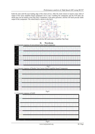
1.2.3. Double Tail Comparator with the Symmetric S-R Latch[2][3]:-
Combing the Sense Amplifier based Comparator and the S-R latch forms the Sense Amplifier Flip Flop
(SAFF). In the Flip Flop, the comparator used as the pulse generator and the S-R latch is the slave latch. As a
result of the change in the clock and date, the comparator generate a pulse and this pulse in turn sets the slave
latch. The sense amplifier based comparator provide monotonic transitions from one to zero logic level on the
outputs, following the leading clock edge. Any subsequent change of the data during the active clock interval
will not affect the output of the sense amplifier based comparator. The S-R latch captures the transition and](https://image.slidesharecdn.com/f0143741-140511234832-phpapp02/85/Performance-analysis-of-High-Speed-ADC-using-SR-F-F-3-320.jpg)
![Performance analysis of High Speed ADC using SR F/F
www.iosrjournals.org 41 | Page
1.6. Transient response of SR latch
Fig. 10
1.7. Transient response of symmetric SR latch
Fig.11
III. Results
Table 1.
S.NO DESIGN DELAY in
180 nm
DELAY
in 90nm
1. Conventional sense amplifier comparator 0.22ns 0.15ns
2. Double tail sense amplifier based comparator 0.17ns 0.106ns
3. Double tail sense amplifier based comparator with SR latch
(SAFF) ,delay between the Q and Q_b
0.029ns 0.011ns
4. Conventional SR latch ,delay between the Q and Q_b 0.082ns 0.044ns
5. Symmetric SR latch ,delay between the Q and Q_b 0.035 ns 0.019ns
The average power dissipated in conventional sense amp is 63.6 pW(180nm),36.9pW(90nm) and in
SAFF it is 42.1 pW. in 180 nm and 24.01 pW in 90nm
IV. Conclusion
1) The output of conventional sense based amp has been found to unstable and having delay.
2) The double tail current sense based comparator has fast response but unstable output.
3) The double tail current sense based comparator with symmetric SR latch(saff) has fast response and stable
output.
4) The design has less delay and less power dissipation in 90 nm technology.
REFERENCES
[1] T. N. B. Wicht and D. Schmitt-Landsiedel, “Yield and Speed Optimization a Latch-Type Voltage Sense Amplifier,”Solid-State
Circuits, IEEE Journal of, vol. 39, pp. 1148–1158, July 2004.
[2] E. A. v. T. D. Schinkel, E. Mensink and B. A. Nauta, “A Double-Tail Latch-Type Voltage Sense Amplifier with 18ps Setup+Hold
Time,” Solid- State Circuits Conference, 2007. ISSCC 2007. Digest of Technical Papers. IEEE International.
[3] V. S. W. J. J. K. C. B. Nikolic, V. G. Oklobdzija and M. Leung, “Improved sense-amplifier-based flip-flop: Design and
measurements,” Solid-State Circuits, IEEE Journal of, vol. 35, pp. 876–884, June 2000.
[4] Reference /text book ken-martin.](https://image.slidesharecdn.com/f0143741-140511234832-phpapp02/85/Performance-analysis-of-High-Speed-ADC-using-SR-F-F-5-320.jpg)

This document analyzes the performance of a high-speed analog-to-digital converter (ADC) using a sense amplifier flip-flop (SAFF). It describes the design of a double tail current sense amplifier-based comparator combined with a symmetric set-reset (SR) latch. This design offers faster response and more stable output compared to conventional designs. Simulation results in 180nm and 90nm show the proposed SAFF has lower delay between outputs and lower power dissipation. Specifically, the delay between outputs is 0.029ns in 180nm and 0.011ns in 90nm for the proposed design, providing faster and more stable operation for high-speed ADCs compared to traditional comparator and latch designs.


![Analysis and design_of_a_low-voltage_low-power[1]](https://cdn.slidesharecdn.com/ss_thumbnails/analysisanddesignofalow-voltagelow-power1-140802050345-phpapp02-thumbnail.jpg?width=640&height=640&fit=bounds)


