Downloaded 754 times


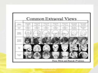
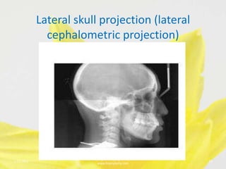
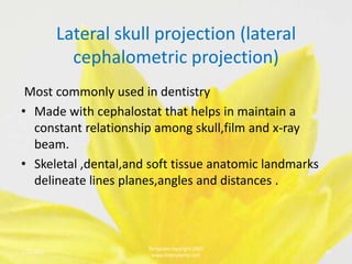


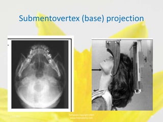


This document discusses various extraoral radiographic techniques used in dentistry. It provides details on patient and image receptor positioning, location of the central x-ray beam, and landmarks visualized for lateral skull projections, submentovertex projections, Waters projections, posterioanterior skull projections, and reverse Towne projections. Proper positioning is important to obtain diagnostic images and visualize anatomic structures symmetrically.


