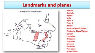
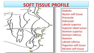
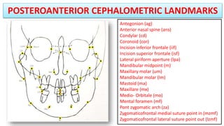
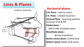
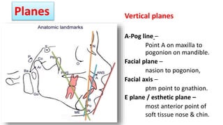
Cephalometrics in Orthodontics
Dr. Shweta Kolhe
BDS, MDS(Orthodontist)
• The Assessment of cranio-facial structure forms a
part of orthodontic diagnosis.
• Earliest method – artistic standards, harmony,
symmetry and beauty.
• Now, using standardized skull radiograph –
facial, dental and skeletal relationships as well as
airway analysis
Introduction
• Roentgen 1895 – Discover X-ray.
• Paccini 1922 – standerdized radiographic head
images at 2meterfrom X-ray tube.
• Boardbent 1931 USA & Hofrath in Germany –
standerdizzed cephalometric technique.
History
• CEPHLO means head , METRIC means measurement.
• Cephalometric Analysis - a collection of data intended to
compress as much of information from the cephalogram into a
usable form for diagnosis, treatment planning and/or
assessment of treatment effects.
• According to Moyer, cephalometrics is a radiographic technique
for abstracting the human head into a geometric shape.
DEFINITION
Types of cephalograms
1) Lateral Cephalogram
• Lateral view of skull
• X-ray beam perpendicular to the patient's sagittal plane
2) Frontal Cephalogram
• Anteroposterior view of skull
• X-ray beam perpendicular to the patient’s coronal plane
Uses of cephalograms
• In orthodontic diagnosis and treatment planning.
– Assesment of horizontal/vertical skeletal relationship, incisor
position/inclination, soft tissue profile
– Orthognathic surgery
• Helps in classification of skeletal and dental abnormalities.
• Helps in evaluation of treatment results.
– Post-functional to assess skeletal/dental relationship
– Plan retention and monitor post retention phase
• Helps in predicting growth related changes.
• Research purpose
Technical Aspects
• Collimated X-ray source - 5 feet from mid-sagittal plane of patient
• Cephalostat - head positioner(with 2 ear rods and forehead clamp)
• Aluminium wedge/ Barium paste - increases soft tissue definition
• Film - placed 1.5-1.8 foot behind mid-sagittal plane of patient with
rare earth metal intensifying screen
Cephalostat
Ear rods
Forehead clamp
Positioning of the patient
• Frankfurt Horizontal plane should
be parallel to floor.
• Ear rods stabilize the patient on the
horizontal plane.
• Forehead clamp should be fixed for
vertical plane stabilization of
patient.
• Patient is made to close the mouth
in centric occlusion.
Evaluation of Cephalometric Radiograph
• Digitizing
– Specialized software used to produce tracing
• Hand Tracing
– Carried out in a darkened room with (X-ray viewer)
– Acetate sheets used as transparency facilitates landmark
identification and secured using masking tape
– Sharp pencil used ( 0.3mm leaded propelling pencil)
– Bilateral landmarks, unless directly super imposed, an
average of two should be taken
Cephalometry Tracing
Hand tracing Digital tracing
TRACING EQUIPMENTS
1. A lateral cephalogram, the usual dimensions of 8x10 inches.
2. Acetate matte tracing paper (0.003 inches thick, 8x10 inches).
3. A sharp 3H drawing pencil or a very fine felt-tipped pen.
4. Masking tape.
5. View box.
6. A protractor.
A landmark is a point serving as a guide for measurement. An ideal landmark is
located reliably on the skull and behaves consistently during growth.
The reliability (reproducibility, dependability) of a landmark is affected by:
1. The quality of the cephalogram
2. The experience of the tracer
3. Confusion with other anatomic shadows.
The validity (correctness or use as proof) of the landmark is determined largely by
the way the landmark is used.
Cephalometric Landmarks
Cephalometric landmarks and measure points should have the
following attributes
1. Landmarks should be easily seen, uniform in outline, easily
reproducible.
2. Lines and planes should have significant relationship to the vectors
of growth of specific areas of the skull.
3. Landmark should permit valid measurements of lines and angles
projected.
4. Measurements should be amenable to statistical analyses.
1. Anatomic landmarks – actual
anatomic structure.
2. Implants
3. Derived landmarks –obtained
secondarily from anatomic structure.
a. External points
b. Intersections of edges of
regression
c. Intersections of constructed lines
POINTS AND LANDMARKS—CLASSIFIED
1. Soft tissue landmark
2. Hard tissue landmark
1. Points/landmarks
2. Planes/line
a. Horizontal plane
b. Vertical plane
• Implants are artificially inserted radio-opaque markers.
• They are "private points" and their position can vary.
• They may be located more precisely than traditional points and provide precise
super positioning
• Ideal for longitudinal studies on the same subject.
• Anatomic "points" are really small regions,
• Each point has its own scale and its own uncertainty in one or two dimensions.
Examples - the anterior nasal spine (ANS). Infradentale (ID) and Nasion (Na).
TRUE ANATOMIC POINTS
IMPLANTS
Derived or created for the purpose of comparison or calculations of the
cephalograms.
These are of the following three types.
a. External Points
• These points are extremes of curvature, e.g. incision superius (Is)
• Points whose coordinates are largest or smallest of all points on a specific
outline, (e.g. "A point", "B Point". Gnathion (Gn), or Condylion (Co)
• These points have less precision of location than true anatomic points.
Derived Points
b. Intersection of Edges of Regression as "Points"
• "Points" defined as the intersection of images
• For instance, articulare (Ar) and -Pterygomaxillary fissure (PTM)
• Such "points" exist only in projections and are dependent on subject
positioning.
c. Intersection of Constructed Lines
• Intersection of constructed lines are used as points.
• e.g. Gonion sometimes is defined as the intersection of the ramal and
mandibular lines.
Landmarks and planes
Nasion
Orbitale
Porion
Sella
Point A
Point B
Basion
Anterior Nasal Spine
Posterior Nasal Spine
Gonion
Condylion
Articulare
Pogonion
Menton
Gnathion
Ptm point
Bolton Point
Landmarks
SOFT TISSUE PROFILE
Glabella
Nasion soft tissue
Pronasale
Subnasale
Labrale superius
Superior labial sulcus
Stomion superius
Stomion inferius
Stomion
Labrale inferius
Pogonion soft tissue
Menton soft tissue
SOFT TISSUE PROFILE
• G (glabella) - Most prominent point in the midsagittal plane of forehead
• ILS (inferior labial sulcus) - Point of greatest concavity in the midline of the lower lip
• Li ( labrale inferius)- Median point in the lower margin of lower membranous lip
• Ls (labrale superius)- Median point in the upper margin of the upper membranous lip
• Ms (menton soft tissue)- Constructed point of intersection of a vertical coordinate from
menton and the inferior soft tissue contour of the chin
• Ns (nasion soft tissue)- Point of deepest concavity of the soft tissue contour of the root of
the nose
• Pn (pronasale)- Most prominent point on the nose
• Pos (pogonion soft tissue)- Most prominent point on the soft tissue contour of the chin
• Sls (superior labial sulcus)- Point of greatest concavity in the midline of upper lip
• Sn (subnasale)- Point where the lower border of the nose meets the outer contour of
upper lip
• St (stomion)- Midpoint between stomion superioris and stomion inferius
• Sti (stomion inferius)- Highest point on lower lip
• Sts (stomion superioris)- Lowest point on upper lip.
POSTEROANTERIOR CEPHALOMETRIC LANDMARKS
Antegonion (ag)
Anterior nasal spine (ans)
Condylar (cd)
Coronoid (cor)
Incision inferior frontale (iif)
Incision superior frontale (isf)
Lateral piriform aperture (lpa)
Mandibular midpoint (m)
Maxillary molar (um)
Mandibular molar (lm)
Mastoid (ma)
Maxillare (mx)
Medio- Orbitale (mo)
Mental foramen (mf)
Pont zygomatic arch (za)
Zygomaticofrontal medial suture point in (mzmf)
Zygomaticofrontal lateral suture point out (lzmf)
Horizontal planes
S.N. Plane – sella to nasion.
F.H. Plane – orbitale to porion.
Occlusal Plane – bisecting posterior
occlusion of M & PM
Palatal plane –
ANS to PNS of palatine bone.
Mandibular plane –
gonion to gnathion.
Basion-nasion plane / Cranial base
Bolton’s plane- Bolton pt & nasion
Lines & Planes
Bo
Vertical planes
A-Pog line –
Point A on maxilla to
pogonion on mandible.
Facial plane –
nasion to pogonion,
Facial axis –
ptm point to gnathion.
E plane / esthetic plane –
most anterior point of
soft tissue nose & chin.
Planes

Cephalometrics

  • 1.
    Cephalometrics in Orthodontics Dr.Shweta Kolhe BDS, MDS(Orthodontist)
  • 2.
    • The Assessmentof cranio-facial structure forms a part of orthodontic diagnosis. • Earliest method – artistic standards, harmony, symmetry and beauty. • Now, using standardized skull radiograph – facial, dental and skeletal relationships as well as airway analysis Introduction
  • 3.
    • Roentgen 1895– Discover X-ray. • Paccini 1922 – standerdized radiographic head images at 2meterfrom X-ray tube. • Boardbent 1931 USA & Hofrath in Germany – standerdizzed cephalometric technique. History
  • 4.
    • CEPHLO meanshead , METRIC means measurement. • Cephalometric Analysis - a collection of data intended to compress as much of information from the cephalogram into a usable form for diagnosis, treatment planning and/or assessment of treatment effects. • According to Moyer, cephalometrics is a radiographic technique for abstracting the human head into a geometric shape. DEFINITION
  • 5.
    Types of cephalograms 1)Lateral Cephalogram • Lateral view of skull • X-ray beam perpendicular to the patient's sagittal plane 2) Frontal Cephalogram • Anteroposterior view of skull • X-ray beam perpendicular to the patient’s coronal plane
  • 6.
    Uses of cephalograms •In orthodontic diagnosis and treatment planning. – Assesment of horizontal/vertical skeletal relationship, incisor position/inclination, soft tissue profile – Orthognathic surgery • Helps in classification of skeletal and dental abnormalities. • Helps in evaluation of treatment results. – Post-functional to assess skeletal/dental relationship – Plan retention and monitor post retention phase • Helps in predicting growth related changes. • Research purpose
  • 7.
    Technical Aspects • CollimatedX-ray source - 5 feet from mid-sagittal plane of patient • Cephalostat - head positioner(with 2 ear rods and forehead clamp) • Aluminium wedge/ Barium paste - increases soft tissue definition • Film - placed 1.5-1.8 foot behind mid-sagittal plane of patient with rare earth metal intensifying screen
  • 8.
  • 9.
    Positioning of thepatient • Frankfurt Horizontal plane should be parallel to floor. • Ear rods stabilize the patient on the horizontal plane. • Forehead clamp should be fixed for vertical plane stabilization of patient. • Patient is made to close the mouth in centric occlusion.
  • 10.
    Evaluation of CephalometricRadiograph • Digitizing – Specialized software used to produce tracing • Hand Tracing – Carried out in a darkened room with (X-ray viewer) – Acetate sheets used as transparency facilitates landmark identification and secured using masking tape – Sharp pencil used ( 0.3mm leaded propelling pencil) – Bilateral landmarks, unless directly super imposed, an average of two should be taken
  • 11.
  • 12.
    TRACING EQUIPMENTS 1. Alateral cephalogram, the usual dimensions of 8x10 inches. 2. Acetate matte tracing paper (0.003 inches thick, 8x10 inches). 3. A sharp 3H drawing pencil or a very fine felt-tipped pen. 4. Masking tape. 5. View box. 6. A protractor.
  • 13.
    A landmark isa point serving as a guide for measurement. An ideal landmark is located reliably on the skull and behaves consistently during growth. The reliability (reproducibility, dependability) of a landmark is affected by: 1. The quality of the cephalogram 2. The experience of the tracer 3. Confusion with other anatomic shadows. The validity (correctness or use as proof) of the landmark is determined largely by the way the landmark is used. Cephalometric Landmarks
  • 14.
    Cephalometric landmarks andmeasure points should have the following attributes 1. Landmarks should be easily seen, uniform in outline, easily reproducible. 2. Lines and planes should have significant relationship to the vectors of growth of specific areas of the skull. 3. Landmark should permit valid measurements of lines and angles projected. 4. Measurements should be amenable to statistical analyses.
  • 15.
    1. Anatomic landmarks– actual anatomic structure. 2. Implants 3. Derived landmarks –obtained secondarily from anatomic structure. a. External points b. Intersections of edges of regression c. Intersections of constructed lines POINTS AND LANDMARKS—CLASSIFIED 1. Soft tissue landmark 2. Hard tissue landmark 1. Points/landmarks 2. Planes/line a. Horizontal plane b. Vertical plane
  • 16.
    • Implants areartificially inserted radio-opaque markers. • They are "private points" and their position can vary. • They may be located more precisely than traditional points and provide precise super positioning • Ideal for longitudinal studies on the same subject. • Anatomic "points" are really small regions, • Each point has its own scale and its own uncertainty in one or two dimensions. Examples - the anterior nasal spine (ANS). Infradentale (ID) and Nasion (Na). TRUE ANATOMIC POINTS IMPLANTS
  • 17.
    Derived or createdfor the purpose of comparison or calculations of the cephalograms. These are of the following three types. a. External Points • These points are extremes of curvature, e.g. incision superius (Is) • Points whose coordinates are largest or smallest of all points on a specific outline, (e.g. "A point", "B Point". Gnathion (Gn), or Condylion (Co) • These points have less precision of location than true anatomic points. Derived Points
  • 18.
    b. Intersection ofEdges of Regression as "Points" • "Points" defined as the intersection of images • For instance, articulare (Ar) and -Pterygomaxillary fissure (PTM) • Such "points" exist only in projections and are dependent on subject positioning. c. Intersection of Constructed Lines • Intersection of constructed lines are used as points. • e.g. Gonion sometimes is defined as the intersection of the ramal and mandibular lines.
  • 19.
    Landmarks and planes Nasion Orbitale Porion Sella PointA Point B Basion Anterior Nasal Spine Posterior Nasal Spine Gonion Condylion Articulare Pogonion Menton Gnathion Ptm point Bolton Point
  • 20.
  • 21.
    SOFT TISSUE PROFILE Glabella Nasionsoft tissue Pronasale Subnasale Labrale superius Superior labial sulcus Stomion superius Stomion inferius Stomion Labrale inferius Pogonion soft tissue Menton soft tissue
  • 22.
    SOFT TISSUE PROFILE •G (glabella) - Most prominent point in the midsagittal plane of forehead • ILS (inferior labial sulcus) - Point of greatest concavity in the midline of the lower lip • Li ( labrale inferius)- Median point in the lower margin of lower membranous lip • Ls (labrale superius)- Median point in the upper margin of the upper membranous lip • Ms (menton soft tissue)- Constructed point of intersection of a vertical coordinate from menton and the inferior soft tissue contour of the chin • Ns (nasion soft tissue)- Point of deepest concavity of the soft tissue contour of the root of the nose • Pn (pronasale)- Most prominent point on the nose • Pos (pogonion soft tissue)- Most prominent point on the soft tissue contour of the chin • Sls (superior labial sulcus)- Point of greatest concavity in the midline of upper lip • Sn (subnasale)- Point where the lower border of the nose meets the outer contour of upper lip • St (stomion)- Midpoint between stomion superioris and stomion inferius • Sti (stomion inferius)- Highest point on lower lip • Sts (stomion superioris)- Lowest point on upper lip.
  • 23.
    POSTEROANTERIOR CEPHALOMETRIC LANDMARKS Antegonion(ag) Anterior nasal spine (ans) Condylar (cd) Coronoid (cor) Incision inferior frontale (iif) Incision superior frontale (isf) Lateral piriform aperture (lpa) Mandibular midpoint (m) Maxillary molar (um) Mandibular molar (lm) Mastoid (ma) Maxillare (mx) Medio- Orbitale (mo) Mental foramen (mf) Pont zygomatic arch (za) Zygomaticofrontal medial suture point in (mzmf) Zygomaticofrontal lateral suture point out (lzmf)
  • 25.
    Horizontal planes S.N. Plane– sella to nasion. F.H. Plane – orbitale to porion. Occlusal Plane – bisecting posterior occlusion of M & PM Palatal plane – ANS to PNS of palatine bone. Mandibular plane – gonion to gnathion. Basion-nasion plane / Cranial base Bolton’s plane- Bolton pt & nasion Lines & Planes Bo
  • 26.
    Vertical planes A-Pog line– Point A on maxilla to pogonion on mandible. Facial plane – nasion to pogonion, Facial axis – ptm point to gnathion. E plane / esthetic plane – most anterior point of soft tissue nose & chin. Planes