Downloaded 624 times
![IS : 1343 - 1980
( Continued from page 1 )
Members Representing
SHRI S. K. LAHA The Institution of Engineers (India), Calcutta
SHRI B. T. UNWALLA ( Alternate )
DR MOHAN RAI Central Building Research Institute (CSIR), Roorkee
DR S. S. REHSI ( Alternate )
SHRI K. K. NAMBIAR In personal capacity ( ‘Ramanalaya’ 11 First Crescent
Park Road, Gandhi Nagar, Adyar, Madras )
SHRI H. S. PASRICHA Hindustan Prefab Ltd, New Delhi
SHRI C. S. MISHRA ( Alternate )
DR M. RAMAIAH Structural Engineering Research Centre (CSIR),
Roorkee
DR N. S. BHAL ( Alternate )
SHRI G. RAMDAS Directorate General of Supplies and Disposals, New
Delhi
DR A. V. R. RAO National Buildings Organization, New Delhi
SHRI J. SEN GUPTA ( Alternate )
SHRI R. V. CHALAPATHI RAO Geological Survey of India, Calcutta
SHRI S. ROY ( Alternate )
SHRI T. N. S. RAO Gammon India Ltd, Bombay
SHRI S. R. PINHEIRO ( Alternate )
SHRI ARJUN RIJHSINGHANI Cement Corporation of India Ltd, New Delhi
SHRI K. VITHAL RAO ( Alternate )
SECRETARY Central Board of Irrigation and Power, New Delhi
DEPUTY SECRETARY (I) ( Alternate )
SHRI N. SIVAGURU Roads Wing, Ministry of Shipping and Transport,
New Delhi
SHRI R. L. KAPOOR ( Alternate )
SHRI K. A. SUBRAMANIAM The India Cements Ltd, Madras
SHRI P. S. RAMACHANDRAN ( Alternate )
SUPERINTENDING ENGINEER Public Works Department, Government of Tamil
(DESIGNS) Nadu, Madras
EXECUTIVE ENGINEER (SM & R
DIVISION) ( Alternate )
SHRI L. SWAROOP Dalmia Cement (Bharat) Ltd, New Delhi
SHRI A. V. RAMANA ( Alternate )
SHRI B. T. UNWALLA The Concrete Association of India, Bombay
SHRI Y. K. MEHTA ( Alternate )
SHRI D. AJITHA SIMHA,
Deputy Director General
[Former Director (Civ Engg)] Director General, ISI ( Ex-officio Member )
SHRI G. RAMAN,
Director (Civ Engg)
Former Secretary
SHRI D. AJITHA SIMHA
Deputy Director General
[Former Director (Civ Engg)], ISI
Secretary
SHRI M. N. NEELAKANDHAN
Assistant Director (Civ Engg), ISI
( Continued on page 61 )
2](https://image.slidesharecdn.com/26678635-is-code-1343-for-pre-stressed-concrete-120530161353-phpapp02/85/26678635-is-code-1343-for-pre-stressed-concrete-3-320.jpg)
![IS : 1343 - 1980
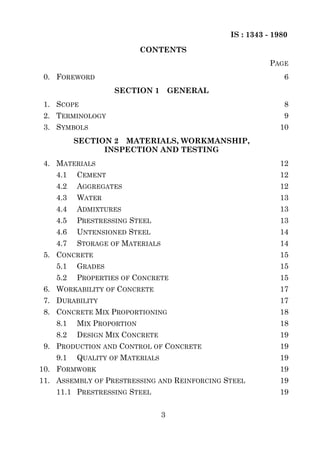
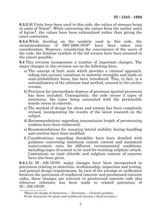
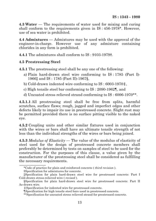
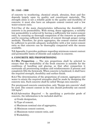
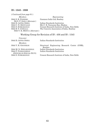
4.5.3.1 Where it is not possible to ascertain the modulus of elasticity
by test or from the manufacturer of the steel, the following values may
be adopted:
Type of Steel Modulus of Elasticity,
E, kN/mm2
Plain cold-drawn wires [conforming to 210
IS : 1785 (Part I)-1966*, IS : 1785
(Part II)-1967† and IS : 6003-1970‡]
High tensile steel bars rolled or 200
heat-treated (conforming to IS : 2090-
1962§)
Strands (conforming to IS : 6006-1970|
|) 195
4.6 Untensioned Steel — Reinforcement used as untensioned steel
shall be any of the following:
a) Mild steel and medium tensile steel bars conforming to IS : 432
(Part I)-1966¶,
b) Hot-rolled deformed bars conforming to IS : 1139-1966**,
c) Cold-twisted bars conforming to IS : 1786-1979††, and
d) Hard-drawn steel wire fabric conforming to IS : 1566-1967‡‡.
4.7 Storage of Materials — Storage of materials shall be as per
IS : 4082-1978§§.
*Specification for plain hard-drawn steel wire for prestressed concrete: Part I Cold
drawn stress-relieved wire ( revised ).
†Specification for plain hard drawn steel wire for prestressed concrete: Part II As-
drawn wire.
‡Specification for indented wire for prestressed concrete.
§Specification for high tensile steel bars used in prestressed concrete.
|
|Specification for uncoated stress relieved strand for prestressed concrete.
¶Specification for mild steel and medium tensile steel bars and hard drawn steel wire
for concrete reinforcement: Part I Mild steel and medium tensile steel bars ( second
revision ).
**Specification for hot rolled mild steel, medium tensile steel and high yield strength
steel deformed bars for concrete reinforcement ( revised ).
††Specification for cold-worked steel high strength deformed bars for concrete
reinforcement ( second revision ).
‡‡Specification for hard-drawn steel wire fabric for concrete reinforcement ( first
revision ).
§§Recommendations on stacking and storage of construction materials at site.
14](https://image.slidesharecdn.com/26678635-is-code-1343-for-pre-stressed-concrete-120530161353-phpapp02/85/26678635-is-code-1343-for-pre-stressed-concrete-15-320.jpg)
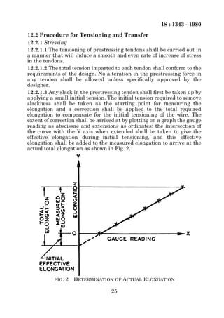
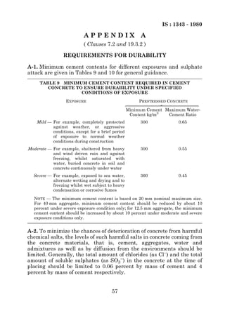
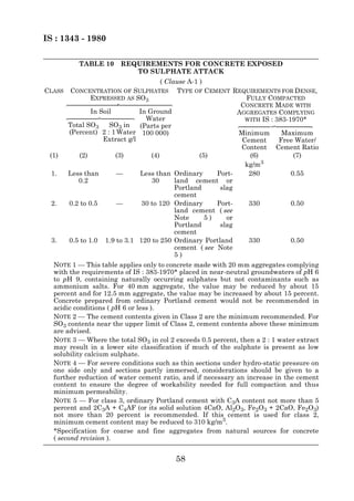
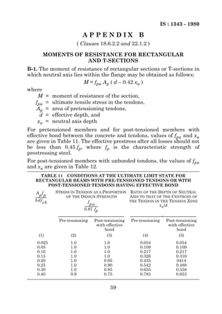
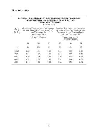

This document is the Indian Standard Code of Practice for Prestressed Concrete (First Revision). It provides guidelines for the structural use of prestressed concrete, covering both on-site work and precast prestressed concrete units. The code contains four sections dealing with general provisions, materials/workmanship/testing, general design requirements, and structural design using the limit state method. It incorporates changes from the previous version to unify prestressed and reinforced concrete provisions and introduce limit state design concepts.