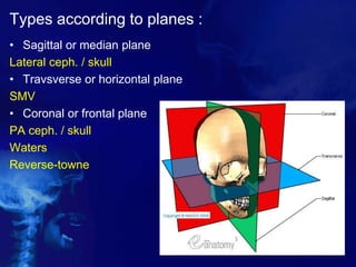
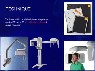
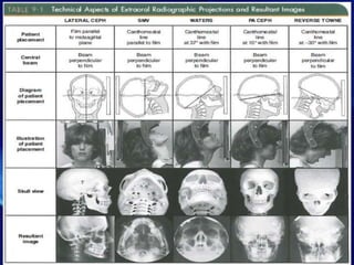
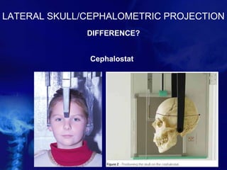
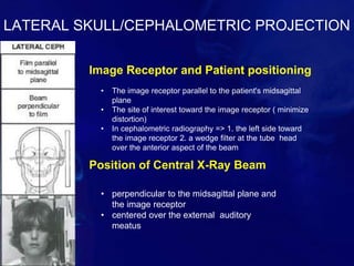
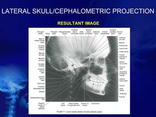
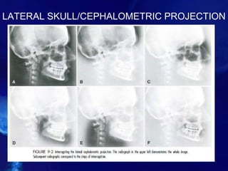
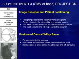
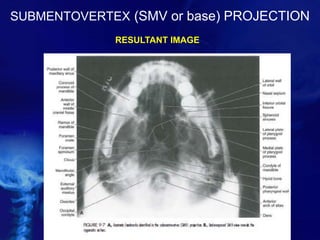
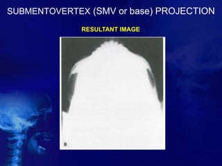
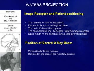
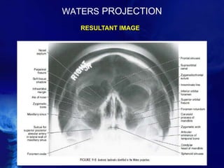
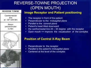
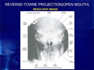
In The Name Of God
Extraoral projections
Chapter 9 white
Present by :
dr. Maedeh Aminian
dr. Maryam Ghazizadeh
Types according to planes :
• Sagittal or median plane
Lateral ceph. / skull
• Travsverse or horizontal plane
SMV
• Coronal or frontal plane
PA ceph. / skull
Waters
Reverse-towne
Selection criteria:
 To examine areas not fully covered by intraoral
films
 To evaluate the cranium, face (including the
maxilla and mandible), or cervical
 To evaluate the relationship between various oro-
facial and dental structures, growth and
development of the face, or treatment progression
• First step in obtaining and interpreting a radiograph
=> Selecting the appropriate extraoral
radiographic examination
• For spatially localizing pathology, usually at least
two radiographs taken at right angles to each
another are obtained
TECHNIQUE
Cephalometric and skull views require at
least a 20 cm x 25 cm (8 inch x 10 inch)
image receptor
The proper Exposure parameters
depend on:
• the patient's size, Anatomy & head
orientation
• image receptor speed
• x-ray source to receptor distance
• grids +/-
Patient kV mA
Hand Wrist 60 2
Child(6 and under) 64 5
Adult Female / Small Male 66 5
Adult Male 68 5
Large Adult 70 5
Grids
 reduce scattered radiation
 improve contrast and resolution
 higher patient exposure
 improve the radiographic appearance of fine
structures, such as trabecular architecture
 aid in the diagnosis of disease
 Cephalometry does not require the use of grids
Proper positioning
Main Anatomic landmark:
Cantho-meatal line =
Orbito-meatal line =
radiographic baseline
EVALUATION OF THE IMAGE
Extraoral images should first be evaluated for
overall quality
The first step in the interpretation of
radiographic images is the identification of
anatomy
EVALUATION OF THE IMAGE
LATERAL SKULL/CEPHALOMETRIC PROJECTION
DIFFERENCE?
Cephalostat
LATERAL SKULL/CEPHALOMETRIC PROJECTION
Image Receptor and Patient positioning
Position of Central X-Ray Beam
• The image receptor parallel to the patient's midsagittal
plane
• The site of interest toward the image receptor ( minimize
distortion)
• In cephalometric radiography => 1. the left side toward
the image receptor 2. a wedge filter at the tube head
over the anterior aspect of the beam
• perpendicular to the midsagittal plane and
the image receptor
• centered over the external auditory
meatus
LATERAL SKULL/CEPHALOMETRIC PROJECTION
RESULTANT IMAGE
LATERAL SKULL/CEPHALOMETRIC PROJECTION
PA SKULL/CEPHALOMETRIC PROJECTION
PA Cephalogram
=> mainly used for evaluation of
facial asymmetries and for
assessment of orthognathic surgery
outcomes involving the patient's
midline or mandibular-maxillary
relationship
PA SKULL/CEPHALOMETRIC PROJECTION
Image Receptor and Patient positioning
Position of Central X-Ray Beam
• Image receptor => in front of the patient / perpendicular to the
midsagittal plane / parallel to the coronal plane
• PA cephalometric => the Canthomeatal line 9-degree with the
horizontal plane/ The Frankfurt plane perpendicular to receptor
• standard PA skull => the canthomeatal line perpendicular to
receptor
• perpendicular to the receptor from the post. to the ant.
• parallel to the patient's midsagittal plane
• centered at the level of the bridge of the nose
PA SKULL/CEPHALOMETRIC PROJECTION
RESULTANT IMAGE
PA SKULL/CEPHALOMETRIC PROJECTION
INTERPRETATION
SUBMENTOVERTEX (SMV or base) PROJECTION
Image Receptor and Patient positioning
Position of Central X-Ray Beam
• Receptor parallel to the patient's transverse plane
• Perpendicular to the midsagittal and coronal planes
• The patient's neck extended as far backward as possible
• The canthomeatal line 10-degree with the receptor
• Perpendicular to the receptor
• from below the mandible toward the vertex of the skull
• 2 cm anterior to a line connecting the right and left condyles
SUBMENTOVERTEX (SMV or base) PROJECTION
RESULTANT IMAGE
SUBMENTOVERTEX (SMV or base) PROJECTION
RESULTANT IMAGE
WATERS PROJECTION
Image Receptor and Patient positioning
Position of Central X-Ray Beam
• The receptor in front of the patient
• Perpendicular to the midsagittal plane
• The patient's head tilted upward
• The canthomeatal line 37-degree with the image receptor
• Open mouth => the sphenoid sinus seen over the palate
• Perpendicular to the receptor
• Centered in the area of the maxillary sinuses
WATERS PROJECTION
RESULTANT IMAGE
REVERSE-TOWNE PROJECTION
(OPEN MOUTH)
Image Receptor and Patient positioning
Position of Central X-Ray Beam
• The receptor in front of the patient
• Perpendicular to the midsagittal plane
• Parallel to the coronal plane
• Patient's head tilted downward
• the canthomeatal line 25 – 30 degree with the receptor
• Open mouth => improve the visualization of the condyles
• Perpendicular to the receptor
• Parallel to the patient's midsagittal plane
• Centered at the level of the condyles
REVERSE-TOWNE PROJECTION(OPEN MOUTH)
RESULTANT IMAGE
Thanks for
your
attention

Extraoral radiography

  • 1.
  • 2.
    Extraoral projections Chapter 9white Present by : dr. Maedeh Aminian dr. Maryam Ghazizadeh
  • 3.
    Types according toplanes : • Sagittal or median plane Lateral ceph. / skull • Travsverse or horizontal plane SMV • Coronal or frontal plane PA ceph. / skull Waters Reverse-towne
  • 4.
    Selection criteria:  Toexamine areas not fully covered by intraoral films  To evaluate the cranium, face (including the maxilla and mandible), or cervical  To evaluate the relationship between various oro- facial and dental structures, growth and development of the face, or treatment progression • First step in obtaining and interpreting a radiograph => Selecting the appropriate extraoral radiographic examination • For spatially localizing pathology, usually at least two radiographs taken at right angles to each another are obtained
  • 5.
    TECHNIQUE Cephalometric and skullviews require at least a 20 cm x 25 cm (8 inch x 10 inch) image receptor
  • 6.
    The proper Exposureparameters depend on: • the patient's size, Anatomy & head orientation • image receptor speed • x-ray source to receptor distance • grids +/- Patient kV mA Hand Wrist 60 2 Child(6 and under) 64 5 Adult Female / Small Male 66 5 Adult Male 68 5 Large Adult 70 5
  • 7.
    Grids  reduce scatteredradiation  improve contrast and resolution  higher patient exposure  improve the radiographic appearance of fine structures, such as trabecular architecture  aid in the diagnosis of disease  Cephalometry does not require the use of grids
  • 8.
    Proper positioning Main Anatomiclandmark: Cantho-meatal line = Orbito-meatal line = radiographic baseline
  • 10.
    EVALUATION OF THEIMAGE Extraoral images should first be evaluated for overall quality The first step in the interpretation of radiographic images is the identification of anatomy
  • 11.
  • 12.
  • 13.
    LATERAL SKULL/CEPHALOMETRIC PROJECTION ImageReceptor and Patient positioning Position of Central X-Ray Beam • The image receptor parallel to the patient's midsagittal plane • The site of interest toward the image receptor ( minimize distortion) • In cephalometric radiography => 1. the left side toward the image receptor 2. a wedge filter at the tube head over the anterior aspect of the beam • perpendicular to the midsagittal plane and the image receptor • centered over the external auditory meatus
  • 14.
  • 15.
  • 16.
  • 17.
  • 18.
  • 19.
    PA SKULL/CEPHALOMETRIC PROJECTION PACephalogram => mainly used for evaluation of facial asymmetries and for assessment of orthognathic surgery outcomes involving the patient's midline or mandibular-maxillary relationship
  • 20.
    PA SKULL/CEPHALOMETRIC PROJECTION ImageReceptor and Patient positioning Position of Central X-Ray Beam • Image receptor => in front of the patient / perpendicular to the midsagittal plane / parallel to the coronal plane • PA cephalometric => the Canthomeatal line 9-degree with the horizontal plane/ The Frankfurt plane perpendicular to receptor • standard PA skull => the canthomeatal line perpendicular to receptor • perpendicular to the receptor from the post. to the ant. • parallel to the patient's midsagittal plane • centered at the level of the bridge of the nose
  • 21.
  • 22.
  • 23.
    SUBMENTOVERTEX (SMV orbase) PROJECTION Image Receptor and Patient positioning Position of Central X-Ray Beam • Receptor parallel to the patient's transverse plane • Perpendicular to the midsagittal and coronal planes • The patient's neck extended as far backward as possible • The canthomeatal line 10-degree with the receptor • Perpendicular to the receptor • from below the mandible toward the vertex of the skull • 2 cm anterior to a line connecting the right and left condyles
  • 24.
    SUBMENTOVERTEX (SMV orbase) PROJECTION RESULTANT IMAGE
  • 25.
    SUBMENTOVERTEX (SMV orbase) PROJECTION RESULTANT IMAGE
  • 26.
    WATERS PROJECTION Image Receptorand Patient positioning Position of Central X-Ray Beam • The receptor in front of the patient • Perpendicular to the midsagittal plane • The patient's head tilted upward • The canthomeatal line 37-degree with the image receptor • Open mouth => the sphenoid sinus seen over the palate • Perpendicular to the receptor • Centered in the area of the maxillary sinuses
  • 27.
  • 28.
    REVERSE-TOWNE PROJECTION (OPEN MOUTH) ImageReceptor and Patient positioning Position of Central X-Ray Beam • The receptor in front of the patient • Perpendicular to the midsagittal plane • Parallel to the coronal plane • Patient's head tilted downward • the canthomeatal line 25 – 30 degree with the receptor • Open mouth => improve the visualization of the condyles • Perpendicular to the receptor • Parallel to the patient's midsagittal plane • Centered at the level of the condyles
  • 29.
  • 31.