Download to read offline
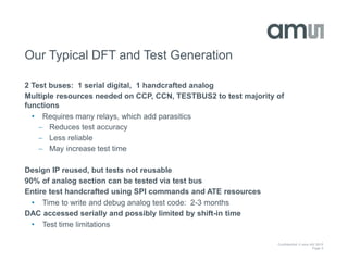

This document summarizes a transition from a traditional DFT and test generation approach to a 1687-based approach for a mixed-signal IC. The traditional flow uses multiple test buses and handcrafted analog tests, requiring months of effort. The 1687 approach aims to streamline testing by accessing analog blocks via scan chains, potentially reducing test time and increasing coverage. While specification coverage would remain the same, defect coverage may increase. Future benefits include reusable test libraries and improved quality for designs using shared IP blocks. A proof of concept simulation showed increased analog defect coverage through improved 1687 access.


![Design for Test [DFT]-1 (1).pdf DESIGN DFT](https://cdn.slidesharecdn.com/ss_thumbnails/designfortestdft-11-231227151941-28a508a3-thumbnail.jpg?width=640&height=640&fit=bounds)


