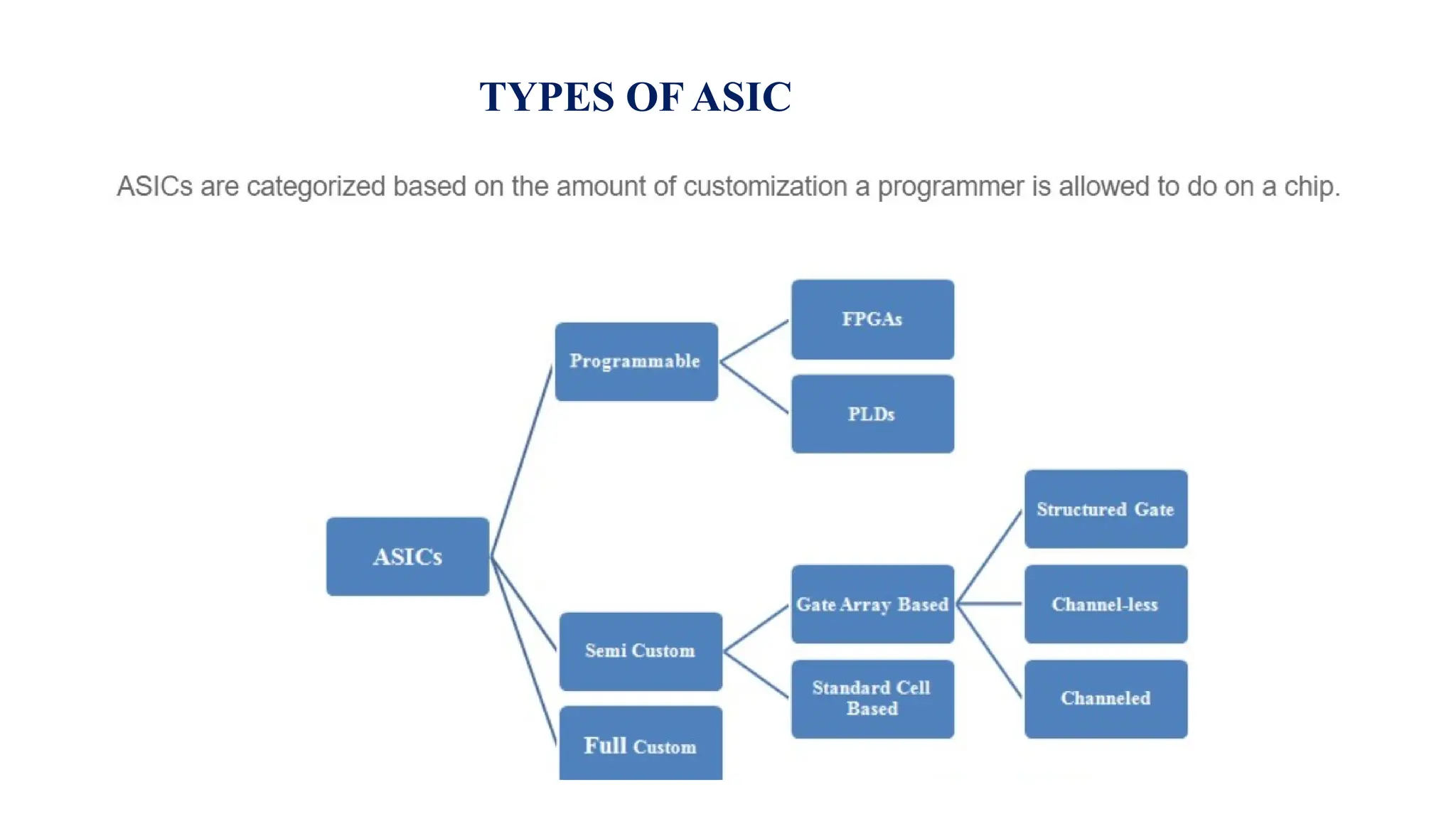
An IC with PGA Package
TYPES OF ASIC
Standard Cell Based ASICS
Layout of a Standard Cell
Routing The Cell-Base IC
Gate Array Based ASICs
1.Channeled Gate-array die
Channel less gate array die
Structured gate array die
Programmable Logic Devices
Field Programmable Gate Array
Design Flow
DATA PATH LOGIC CELLS
INTRODUCTION
DATAPATH ADDER (RCA)
DATAPATH ELEMENTS
SYMBOLS FOR DATA ADDER
ADDERS
CONVENTIONAL RCA IN TERMS OF GENERATE ,PROPAGATE
AND KILL SIGNALS
LOGIC DIAGRAM OF CONVENTIONAL RCA WITH REDUCTION IN THE DELAY BY USING THE GO-FASTER BUBBLE PAIRS
CARRY SAVE ADDER
CONCEPT OF CARRY SAVE ADDER
EQUATIONS AND CONCEPT OF CSA
CSA SYMBOL,DATAPATH ,PIPELINED STRUCTURE
CARRY-BYPASS & CARRY-SKIP ADDERS: CONCEPT,EQUATIONS
LOGIC DIAGRAM
LOOK-AHEAD CARRY ADDER
CARRY - LOOKAHEAD ADDER
BRENT-KUNG CLA
Carry Select Adder
ASIC DESIGN FLOW
FloorPlanning
• The input to floorplanning is a netlist that describes the circuit blocks
and the logic cells within them and their interconnections.
• We should now set aside spaces for interconnections called the
channel.
Floor Planning ---- An Example
The Floorplanning Problem formulation
Goals & Objectives Of floorplanning
Floorplanning inputs
Measurement Of Delay In Floorplanning
Measurement Of Worst Case Interconnect Delay
Example Of Wire Load Table
Floorplanning Tools
Floorplanning Tools
Congestion Analysis
Channel Definition
Channel Routing Order Using a slicing tree
Cyclic Constraints
I/O and Power Planning
Power Planning
Placement
Force Equation
Directed Testing
• Traditionally Direct Tests were used when we had the task of verifying the correctness of
the design.
• We first look at the hardware specifications.
• We then write a verification plan with a list of tests
• Each of these verification tests concentrate on a list of related features
• We then write the stimulus vectors that excersize these features in the DUT
• We then simulate the DUT with these vectors and manually review th eresulting log files
and waveforms to make sure the design does the expected.
• Finally once the test works correctly we verify it wrt the verification plan and move on to
the next test.
• This is incremental approach makes a steady progress.
• It also produces immediate results as little infrastructure is needed to create the
stimulus vector.
• Given ample time and staffing, directed testing is sufficient to verify many designs.
Disadvantages of Directed Testing:
This approach cannot be used when we don’t have the necessary time or resources to carry out directed testing.
When the Design complexity doubles,it takes twice as long to complete or requires twice as many people to implement it.
We cannot use it when we want to find the bugs faster with 100% coverage
Methodology Basics
VLSI LECTURES. of the advanced vlsi module

VLSI LECTURES. of the advanced vlsi module