Download to read offline

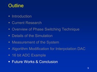

![Confidential © ams AG
Page 18
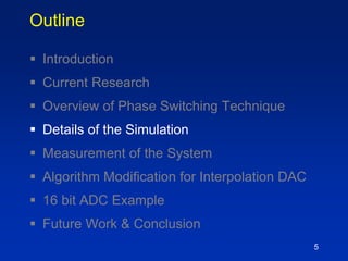
AWG
DAC
CLK
DSP
X XXX
Din
Din
AWG sampling frequency: fs(AWG) = 1/Ts
A
𝐗= Acos(2πfinnTs)
0 0.1 0.2 0.3 0.4 0.5
-300
-200
-100
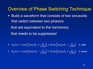
0
Power[dB]
Normalized frequency f/fs
𝐟𝐢𝐧
𝐇𝐃𝟑
In case
Single-tone generation
DAC has 3rd-order distortion
Conventional Signal Generation with
AWG](https://image.slidesharecdn.com/session1a-170425081047/85/A-Technique-for-Dynamic-Range-Improvement-of-Intermodulation-Distortion-Products-for-an-Interpolating-DAC-based-Arbitrary-Waveform-Generator-Using-a-Phase-Switching-Algorithm-18-320.jpg)
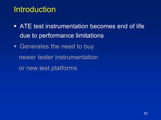
![Confidential © ams AG
Page 19
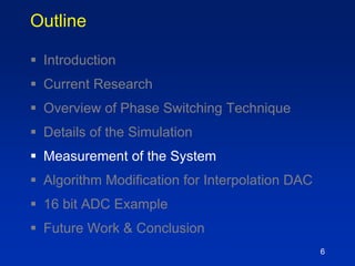
Signal Generation with AWG using
Phase Switching
AWG
DAC
CLK
DSP
X0 X1X0X1
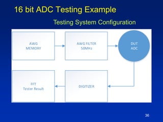
Din
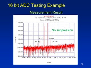
Din
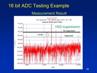
AWG sampling frequency: fs(AWG) = 1/Ts(AWG)
𝐗 𝟎= 1.15Acos(2πfinnTs−π/6)
𝐗 𝟏= 1.15Acos(2πfinnTs+𝜋/6)
0 0.1 0.2 0.3 0.4 0.5
-300
-200
-100
0
𝐟𝐢𝐧
𝐟𝒔/2−𝟑𝐟in
𝐟𝒔/2−𝐟in
Power[dB]
Normalized frequency f/fs
Θ = π/3𝐓𝐬(𝐀𝐖𝐆)
X0
𝐗 𝟏
In case
Single-tone generation
DAC has 3rd-order distortion
HD3 disappears](https://image.slidesharecdn.com/session1a-170425081047/85/A-Technique-for-Dynamic-Range-Improvement-of-Intermodulation-Distortion-Products-for-an-Interpolating-DAC-based-Arbitrary-Waveform-Generator-Using-a-Phase-Switching-Algorithm-19-320.jpg)
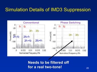
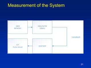
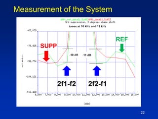
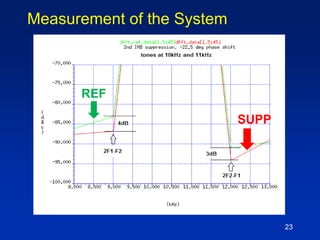
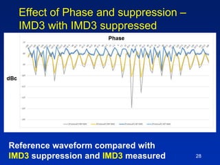
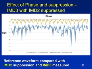
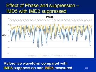
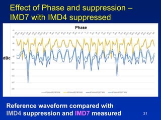
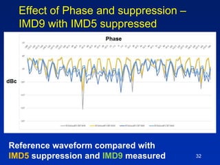
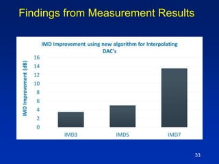
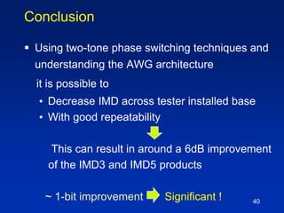


The document presents a technique for improving the dynamic range of intermodulation distortion products in an arbitrary waveform generator using a phase switching algorithm. It discusses the challenges of current test instrumentation limitations and how a simple DSP method can extend performance while driving down testing costs. The findings suggest that this method can yield a significant reduction in IMD levels, which could translate to approximately a 1-bit improvement in ADC performance.

![RF Circuit Design - [Ch1-2] Transmission Line Theory](https://cdn.slidesharecdn.com/ss_thumbnails/ch1-2-150613064349-lva1-app6892-thumbnail.jpg?width=640&height=640&fit=bounds)


![RF Module Design - [Chapter 7] Voltage-Controlled Oscillator](https://cdn.slidesharecdn.com/ss_thumbnails/rfch7-150613070347-lva1-app6892-thumbnail.jpg?width=640&height=640&fit=bounds)


![Multiband Transceivers - [Chapter 1]](https://cdn.slidesharecdn.com/ss_thumbnails/ch1-150613070932-lva1-app6891-thumbnail.jpg?width=640&height=640&fit=bounds)

![RF Module Design - [Chapter 3] Linearity](https://cdn.slidesharecdn.com/ss_thumbnails/rfch3-150613070345-lva1-app6891-thumbnail.jpg?width=640&height=640&fit=bounds)


![RF Circuit Design - [Ch1-1] Sinusoidal Steady-state Analysis](https://cdn.slidesharecdn.com/ss_thumbnails/ch1-1-150613064348-lva1-app6891-thumbnail.jpg?width=640&height=640&fit=bounds)


![RF Circuit Design - [Ch2-1] Resonator and Impedance Matching](https://cdn.slidesharecdn.com/ss_thumbnails/ch2-1-150613064353-lva1-app6892-thumbnail.jpg?width=640&height=640&fit=bounds)
![RF Circuit Design - [Ch3-2] Power Waves and Power-Gain Expressions](https://cdn.slidesharecdn.com/ss_thumbnails/ch3-2-150613064404-lva1-app6891-thumbnail.jpg?width=640&height=640&fit=bounds)
![Circuit Network Analysis - [Chapter2] Sinusoidal Steady-state Analysis](https://cdn.slidesharecdn.com/ss_thumbnails/ch2-150613063856-lva1-app6892-thumbnail.jpg?width=640&height=640&fit=bounds)