Download to read offline
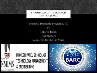
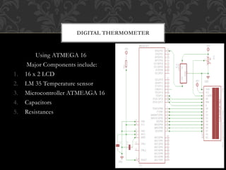
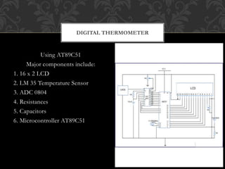
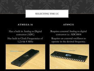
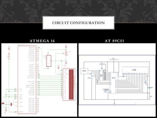
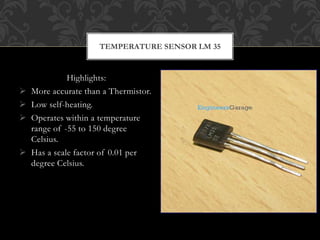
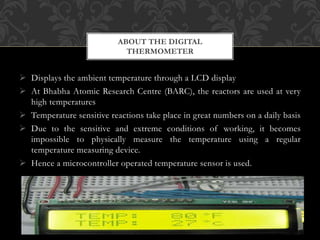
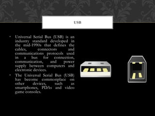
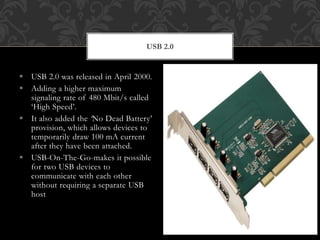


The document summarizes Utkarsh Tiwari's technical internship project at Bhabha Atomic Research Centre. The project involved developing digital thermometers using ATMEGA 16 and AT89C51 microcontrollers. It also studied various fast networking buses including USB, IEEE 1394, JESD 204, PCI Express, JTAG 1149. The document provides details of each microcontroller and networking bus. It concludes that networks are proliferating in industrial automation and it is important to have a strategy to choose from the various options available.