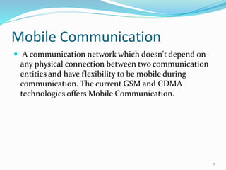
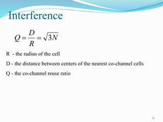
UNIT I
WIRELESS COMMUNICATION
Cellular systems- Frequency Management and Channel Assignment- types of handoff and their characteristics, dropped call rates & their evaluation -MAC – SDMA – FDMA –TDMA – CDMA – Cellular Wireless Networks
Proactive routing protocol
Each node maintain a routing table.
Sequence number is used to update the topology information
Update can be done based on event driven or periodic
Observations
May be energy expensive due to high mobility of the nodes
Delay can be minimized, as path to destination is already known to all nodes.
1: Direct sequence and frequency hopped spread spectrum, spreading sequence and their correlation functions, Acquisition and tracking of spread spectrum signals.
2: Error probability for DS-CDMA, on AWGN channels, DS-CDMA on frequency selective fading, channels, Performance analysis of cellular CDMA.
3: Capacity estimation, Power control, effect of imperfect power control on DS CDMA performance, Soft Handoffs.
4: Spreading /coding tradeoffs, multi-carrier CDMA, IS-95 CDMA system, third generation CDMA systems, multi-user detection.
Cellular network evolved gradually .Generations of computer network like 1st generation (1g) ,second generation (2g) evolved .Then came 3g ,4g, each time with increased speed and security
Ready. Set. Handoff. - Improving the Project Handoff Experience.David Yarde
Project handoffs can get messy but they don't have to be that way. In this presentation we cover the ins and outs of successful project handoffs and how to catch problem areas and improve overall internal project satisfaction.
Gives you the complete knowledge of different channel allocation techniques, reverse and forward CDMA, GSM Frame Structure, GSM channel Types, cellular concepts, handoff strategies, Frequency reuse and GSM call structure.
This PDF provides a in-depth explanation for all the concepts and practices used before.
Presented at the George Washington University 1st GME Retreat. Includes overview of handoff function and content, pitfalls for handoffs, and strategies for safe and effective communication during handoffs, and how to use process improvement techniques to make handoffs safer. Handout includes handoff menu of educational tools to be used by faculty teaching.
This presentation contains the basic of cellular system.
in which direction the cellular system works and how it changes the network from one bast station to another is simply explained.
how Hand-off occur between two base station is shown via figure to understand well.
the cell system in mobile network and the cell spliting, sectoring, microcell zone concept is also explained well.
Please take a look.
may be it is helpfull for you.
Thank you.
Chapter 1 AI is used in Customer Relationship Management (CRM):.pptxfilembarketema
Certainly! Here are some examples of how AI is used in Customer Relationship Management (CRM):
Chatbots: AI-powered chatbots are used in CRM systems to provide automated customer support and assistance. Chatbots can handle a wide range of customer inquiries, answer frequently asked questions, and provide relevant information in real-time. They can engage in natural language conversations, understand customer intent, and provide personalized recommendations or solutions.
Sentiment Analysis: AI algorithms can analyze customer interactions, such as emails, social media posts, and chat transcripts, to determine customer sentiment and emotions. Sentiment analysis helps CRM systems understand customer satisfaction levels, identify potential issues or concerns, and take proactive measures to address them.
Personalization: AI enables CRM systems to deliver personalized experiences to customers. By analyzing customer data, purchase history, browsing behavior, and preferences, AI algorithms can generate personalized product recommendations, targeted marketing campaigns, and customized offers to enhance customer engagement and satisfaction.
Lead Scoring and Qualification: AI can assist in lead scoring and qualification processes. By analyzing historical data and customer behavior patterns, AI algorithms can predict the likelihood of a lead converting into a customer. This helps sales teams prioritize their efforts and allocate resources effectively to high-potential leads, improving conversion rates and sales efficiency.
Predictive Analytics: AI algorithms can analyze customer data and historical patterns to make predictions about customer behavior, such as likelihood to churn or cross-sell/up-sell opportunities. These predictions help CRM systems identify the most effective strategies for customer retention and revenue growth.
Voice and Speech Analytics: AI-powered voice and speech analytics tools can analyze customer calls and extract valuable insights. These tools can identify keywords, sentiment, and speech patterns to understand customer needs, identify common issues, and provide feedback for agent training and process improvement.
Social Media Monitoring: AI algorithms can monitor social media platforms to track brand mentions, customer feedback, and sentiment. This helps CRM systems identify customer concerns, engage in social listening, and respond promptly to customer queries or complaints, improving overall customer satisfaction and brand reputation.
Customer Segmentation: AI can assist in segmenting customers based on various criteria, such as demographics, purchase history, interests, and behavior. This enables CRM systems to tailor marketing campaigns, promotions, and communication strategies to specific customer segments, improving targeting and response rates.
Customer Lifetime Value (CLV) Prediction: This helps CRM
BJT small signal model – Analysis of CE, CB, CC amplifiers- Gain and frequency response – MOSFET small signal model– Analysis of CS and Source follower – Gain and frequency response- High frequency analysis.
Orbits : types of satellites : frequency used link establishment, MA techniques used in satellite communication, earth station; aperture actuators used in satellite – Intelsat and Insat: fibers – types:
sources, detectors used, digital filters, optical link: power line carrier communications: SCADA
AM – Frequency spectrum – vector representation – power relations – generation of AM – DSB, DSB/SC, SSB, VSB AM Transmitter & Receiver; FM and PM – frequency spectrum – power relations : NBFM & WBFM, Generation of FM and DM, Armstrong method & Reactance modulations : FM & PM frequency.
PN junction diode –structure, operation and V-I characteristics, diffusion and transient capacitance - Rectifiers – Half Wave and Full Wave Rectifier,– Display devices- LED, Laser diodes- Zener diodecharacteristics-Zener Reverse characteristics – Zener as regulator,TRANSISTORS, BJT, JFET, MOSFET- structure, operation, characteristics and Biasing UJT, Thyristor and IGBT Structure and characteristics,BJT small signal model – Analysis of CE, CB, CC amplifiers- Gain and frequency response –
MOSFET small signal model– Analysis of CS and Source follower – Gain and frequency response- High frequency analysis,BIMOS cascade amplifier, Differential amplifier – Common mode and Difference mode analysis – FET input stages – Single tuned amplifiers – Gain and frequency response – Neutralization methods, power amplifiers –Types (Qualitative analysis),Advantages of negative feedback – voltage / current, series , Shunt feedback –positive feedback – Condition for oscillations, phase shift – Wien bridge, Hartley, Colpitts and Crystal oscillators.
Multinational Corporations – Environmental Ethics – Computer Ethics – Weapons Development – Engineers as Managers – Consulting Engineers – Engineers as Expert Witnesses and Advisors – Moral Leadership –Code of Conduct – Corporate Social Responsibility
Safety and Risk – Assessment of Safety and Risk – Risk Benefit Analysis and Reducing Risk - Respect for Authority – Collective Bargaining – Confidentiality – Conflicts of Interest – Occupational Crime – Professional Rights – Employee Rights – Intellectual Property Rights (IPR) – Discrimination
Senses of “Engineering Ethics” – Variety of moral issues – Types of inquiry – Moral dilemmas – Moral Autonomy – Kohlberg‟s theory – Gilligan‟s theory – Consensus and Controversy – Models of professional roles - Theories about right action – Self-interest – Customs and Religion – Uses of Ethical Theories
Morals, values and Ethics – Integrity – Work ethic – Service learning – Civic virtue – Respect for others – Living peacefully – Caring – Sharing – Honesty – Courage – Valuing time – Cooperation – Commitment – Empathy – Self confidence – Character – Spirituality – Introduction to Yoga and meditation for professional excellence and stress management.
Trust models for Grid security environment – Authentication and Authorization methods – Grid security infrastructure – Cloud Infrastructure security: network, host and application level – aspects of data security, provider data and its security, Identity and access management architecture, IAM practices in the cloud, SaaS, PaaS, IaaS availability in the cloud, Key privacy issues in the cloud.
Open source grid middleware packages – Globus Toolkit (GT4) Architecture , Configuration – Usage of Globus – Main components and Programming model - Introduction to Hadoop Framework - Mapreduce, Input splitting, map and reduce functions, specifying input and output parameters, configuring and running a job – Design of Hadoop file system, HDFS concepts, command line and java interface, dataflow of File read & File write.
2. UNIT I
WIRELESS COMMUNICATION
Cellular systems- Frequency Management and Channel
Assignment-
types of handoff and their characteristics,
Dropped call rates & their evaluation –
MAC – SDMA – FDMA –TDMA – CDMA –
Cellular Wireless Networks
2
3. Physical Properties of Wireless
• Makes wireless network different from wired
networks.
• Standard ‘wired’ networks are connected together
using copper cables that carry data around the
network in the form of electrical signals.
• In some circumstances laying cables may be
inconvenient or even impossible.
• The answer may be to implement a “wireless”
network to move the data around.
3
4. Wireless = Waves
• Electromagnetic radiation.
• Emitted by sinusoidal current running
through a wire (transmitting antenna).
• Creates propagating sinusoidal magnetic and
electric fields according to Maxwell’s
equations:
• Fields induce current in receiving antenna
4
6. Wireless Communications
Wireless communication is the transfer of information between
two or more points that are not connected by an electrical
conductor. The most common wireless technologies use radio.
Special Note: Wireless can also be interpreted as
“wire-less”, which means to create a network without wires. In
this case, a “wire-less” network may be using infra-red or even
lasers to communicate – this is much rarer than using radio.
6
7. Mobile Communication
A communication network which doesn't depend on
any physical connection between two communication
entities and have flexibility to be mobile during
communication. The current GSM and CDMA
technologies offers Mobile Communication.
7
8. Frequency & Public Use Bands
Propagating sinusoidal wave with
some frequency/wavelength
C (speed of light) = 3x10⁸ m/s
Name 900 Mhz 2.4 Ghz 5 Ghz
Range 902 - 928 2.4 - 2.4835 5.15 - 5.35
Bandwidth 26 Mhz 83.5 Mhz 200 Mhz
Wavelength .33m / 13.1” .125m / 4.9” .06 m / 2.4”
c
f
8
9. Free-space Path-loss
Power of wireless transmission reduces with square of
distance (due to surface area increase of sphere)
Reduction also depends on wavelength
Long wave length (low frequency) has less loss
Short wave length (high frequency) has more loss
2
4
D
PL
9
11. Multi-Path Effect
Multi-path components are delayed depending on path
length (delay spread)
Phase shift causes frequency dependent constructive /
destructive interference
Amplitude
Time
Amplitude
Frequency
11
12. Modulation
Modulation allows the wave to carry information
by adjusting its properties in a time varying way
Amplitude
Frequency
Phase
Digital modulation using discrete “steps” so that
information can be recovered despite
noise/interference
8VSB - US HDTV
BFSK - Mote Sensor Networks
QPSK - 2 Mbps 802.11 & CMDA(IS-95)
12
13. Multi-transmitter Interference
Similar to multi-path
Two transmitting stations will constructively/destructively
interfere with each other at the receiver
Receiver will “hear” the sum of the two signals, which
usually means garbage
13
14. Cellular Network Organization
Use multiple low-power transmitters (100 W or less)
Areas divided into cells
Each served by its own antenna
Served by base station consisting of transmitter, receiver, and
control unit
Band of frequencies allocated
Cells set up such that antennas of all neighbors are equidistant
(hexagonal pattern)
14
16. Frequency Reuse
Adjacent cells assigned different frequencies to avoid
interference or crosstalk
Objective is to reuse frequency in nearby cells
10 to 50 frequencies assigned to each cell
Transmission power controlled to limit power at that frequency
escaping to adjacent cells
The issue is to determine how many cells must intervene
between two cells using the same frequency
16
18. The factor N is called the cluster size and is given
N=i2+ij+j2
A
B
C
A
C
A
C
A
B
C
A F
E
G
D
E
F
D E
18
19. To find the nearest co-channel neighbor of a particular cell,
one must do the following:
move i cells along any chain of hexagons and then
turn 60 degrees counter-clockwise and move j cells.
19
21. Interference
N
R
D
Q 3
R - the radius of the cell
D - the distance between centers of the nearest co-channel cells
Q - the co-channel reuse ratio
21
22. Approaches to Cope with
Increasing Capacity
Adding new channels
Frequency borrowing – frequencies are taken from
adjacent cells by congested cells
Cell splitting – cells in areas of high usage can be split
into smaller cells
Cell sectoring – cells are divided into a number of
wedge-shaped sectors, each with their own set of
channels
Microcells – antennas move to buildings, hills, and
lamp posts
22
24. Cellular Systems Terms
Base Station (BS) – includes an antenna, a controller, and a
number of receivers
Mobile telecommunications switching office (MTSO) –
connects calls between mobile units
Two types of channels available between mobile unit and BS
Control channels – used to exchange information having to
do with setting up and maintaining calls
Traffic channels – carry voice or data connection between
users
24
25. Steps in an MTSO Controlled Call
between Mobile Users
Mobile unit initialization
Mobile-originated call
Paging
Call accepted
Ongoing call
Handoff
25
26. Additional Functions in an MTSO
Controlled Call
Call blocking
Call termination
Call drop-the dropped-call rate (DCR) is the fraction of the telephone
calls which, due to technical reasons, were cut off before the speaking parties had
finished their conversation and before one of them had hung up (dropped calls) This
fraction is usually measured as a percentage of all calls.
Calls to/from fixed and remote mobile subscriber
26
27. Mobile Radio Propagation Effects
Signal strength
Must be strong enough between base station and mobile unit
to maintain signal quality at the receiver
Must not be so strong as to create too much cochannel
interference with channels in another cell using the same
frequency band
Fading
Signal propagation effects may disrupt the signal and cause
errors
27
28. Power Control
Design issues making it desirable to include dynamic
power control in a cellular system
Received power must be sufficiently above the background
noise for effective communication
Desirable to minimize power in the transmitted signal from
the mobile
Reduce cochannel interference, alleviate health concerns, save battery
power
In SS systems using CDMA, it’s desirable to equalize the
received power level from all mobile units at the BS
28
29. Types of Power Control
Open-loop power control
Depends solely on mobile unit
No feedback from BS
Not as accurate as closed-loop, but can react quicker to
fluctuations in signal strength
Closed-loop power control
Adjusts signal strength in reverse channel based on metric
of performance
BS makes power adjustment decision and communicates to
mobile on control channel
29
30. Traffic Engineering
Ideally, available channels would equal number of
subscribers active at one time
In practice, not feasible to have capacity handle all
possible load
For N simultaneous user capacity and L subscribers
L < N – nonblocking system
L > N – blocking system
30
31. Blocking System Performance
Questions
Probability that call request is blocked?
What capacity is needed to achieve a certain upper bound
on probability of blocking?
What is the average delay?
What capacity is needed to achieve a certain average
delay?
31
32. Traffic Intensity
Load presented to a system:
= mean rate of calls attempted per unit time
h = mean holding time per successful call
A = average number of calls arriving during average holding
period, for normalized
hA
32
33. Factors that Determine the Nature
of the Traffic Model
Manner in which blocked calls are handled
Lost calls delayed (LCD) – blocked calls put in a queue
awaiting a free channel
Blocked calls rejected and dropped
Lost calls cleared (LCC) – user waits before another attempt
Lost calls held (LCH) – user repeatedly attempts calling
Number of traffic sources
Whether number of users is assumed to be finite or infinite
33
35. Dropped Call Rate (DCR) is a term in
telecommunications denoting the fraction of the calls
which, due to technical reasons, were cut off before the
speaking parties had finished their conversation and
before one of them had hung up. This fraction is usually
measured as a percentage of all calls.
35
36. Handover or Handoff
Handover basically means changing the point of
connection while communicating.
Old Concept
Whenever Mobile Station is connected to 1 Base
Station and there is a need to change to another
Base Station, it is known as HANDOVER.
37. New Concept
When mobile station switches from one set of radio
resources to another set, HANDOVER is said to have
taken place.
Radio resources
Set I
Radio resources
Set II
HANDOVER
38.
39. Handoff Performance Metrics
Handoff blocking probability – probability that a
handoff cannot be successfully completed
Handoff probability – probability that a handoff occurs
before call termination
Rate of handoff – number of handoffs per unit time
Interruption duration – duration of time during a
handoff in which a mobile is not connected to either
base station
Handoff delay – distance the mobile moves from the
point at which the handoff should occur to the point at
which it does occur
39
40. Handoff Performance Metrics
Cell blocking probability – probability of a new call
being blocked
Call dropping probability – probability that a call is
terminated due to a handoff
Call completion probability – probability that an
admitted call is not dropped before it terminates
Probability of unsuccessful handoff – probability that
a handoff is executed while the reception conditions
are inadequate
40
41. Handoff Strategies Used to
Determine Instant of Handoff
Relative signal strength
Relative signal strength with threshold
Relative signal strength with hysteresis
Relative signal strength with hysteresis and threshold
Prediction techniques
41
42. Handoff- requirement
Mobiles may move out of coverage area of a cell and into
coverage area of a different cell during a call
MSC must identify new BS to handle call
MSC must seamlessly transfer control of call to new BS
MSC must assign call new forward and reverse channels within the
channels of new BS
Some important performance metrics in handoff:
Seamless – user should not know handoff occurring
Minimum unnecessary Handoff due to short time fading
Low probability of blocking new calls in the new cell
Handoff to a good SNR channel so that an admitted call is not
dropped
43. Handoff Main Steps
1. Initiation
2. Resource reservation
3. Execution
4. Completion
Important handoff parameter:
SNRold to initiate handoff based on minimum acceptable
quality
SNRnew of the target channel (SNRnew > SNRold )
D = SNRnew - SNRold dB
If D too small, unnecessary handoffs occur
If D too large, may be insufficient time to complete
handoff before SNRold becomes too weak and signal
is lost
44. HANDOFF DECISIONS
There are numerous methods for performing handoff. From the
decision process point of view, one can find at least three
different kinds of handoff decisions.
Network-Controlled Handoff
Mobile-Assisted Handoff
Mobile-Controlled Handoff
45. Network-Controlled Handoff
• In a network-controlled handoff protocol, the network makes a handoff
decision based on the measurements of the MSs at a number of BSs.
• In general, the handoff process takes 100–200 ms.
• Network-controlled handoff is used in first-generation analog systems such
as AMPS (Advanced Mobile Phone System), TACS(Total Access
Communication System), and NMT (Nordic Mobile Telephone).
Mobile-Assisted Handoff
• In a mobile-assisted handoff process, the MS makes measurements and the
network makes the decision.
• In the circuit-switched GSM (global system mobile), the BS controller (BSC)
is in charge of the radio interface management. This mainly means allocation
and release of radio channels and handoff management.
• The handoff time between handoff decision and execution in a circuit-
switched GSM is approximately 1 second.
46. Mobile-Controlled Handoff
• In mobile-controlled handoff, each MS is completely in control of the
handoff process.
• This type of handoff has a short reaction time (in the order of 0.1 second).
• MS measures the signal strengths from surrounding BSs and interference
levels on all channels.
• A handoff can be initiated if the signal strength of the serving BS is lower
than that of another BS by a certain threshold.
47. TYPES OF HANDOVER
1.Hard handoff - break-before-make
2. Soft handoff- make-before-break
3. Softer handoff- Softer handover is the situation where one base
station receives two user signals from two adjacent sectors it serves.
48. HARD HANDOVER
“BREAK BEFORE MAKE”
• Old connection is broken before a new connection is
activated
• Primarily used in FDMA and TDMA systems (e.g. GSM)
• Different frequency ranges used in adjacent cells to
minimize the interference
49. Mechanism of Hard Handover
The base station BS1 on one cell site hands off the mobile station(MS)’s call
to another cell BS2.
The link to the prior base station, BS1 is terminated before the user is
transferred to the new cell’s base station, BS2. The MS is linked to no more
than one BS at any given time.
50. CHARACTERISTICS
• A Hard handover is relatively cheaper and easier to
implement in comparison to other types of Handover.
• It is primarily used in FDMA (frequency division
multiple access) and TDMA (time division multiple
access), where different frequency ranges are used in
adjacent channels in order to minimize channel
interference.
• It is simpler as phone's hardware does not need to be
capable of receiving two or more channels in parallel.
51. SOFT HANDOVER
“MAKE BEFORE BREAK”
• New connection is activated before the old is broken
• Used in UMTS to improve the signal quality
• Uplink and downlink signals may be combined for
better signal
• A mobile may in UMTS spend a large part of the
connection time in soft handover
• Better connection reliability
• More seamless handover.
53. • The call is first connected to the new base station BS2 and
then it is dropped by the previous base station BS1.
• The call will be established only when a reliable connection
to the target cell is obtained. The MS is linked to two BS for
a brief interval of time. Thus soft handover involves
connection to more than one cell.
54. CHARACTERISTICS
• It offers more reliable access continuity in network connection and less
chances of a call termination during switching of base stations in
comparison to a Hard handoff.
• It is commonly used in CDMA (Code-division multiple access) systems
that enables the overlapping of the repeater coverage zones, so that every
cell phone set is always well within range of at least one of the base
stations.
• Technical implementation of a Soft handoff is more expensive and
complex in comparison to a Hard handoff.
• It is used in sensitive communication services such as videoconferencing.
55. SOFTER HANDOVER
• Softer handover is the situation where one base station
receives two user signals from two adjacent sectors it serves.
• In the case of softer handover the base station receives 2
separated signals through multi-path propagation.
• Due to reflections on buildings or natural barriers the signal
sent from the mobile stations reaches the base station from
two different sectors.
57. INTER-CELL AND INTRA-CELL HANDOVER
•The inter-cell handover switches a call in progress
from one cell to another cell,
• The intra-cell handover switches a call in progress
from one physical channel of a cell to another physical
channel of the same cell.
58. Inter BSC/MSC handoff: This for of GSM handover or GSM handoff occurs when the
mobile moves out of the coverage area of one BTS but into another controlled by the
same BSC/MSC.
Inter system handoff:
If during ongoing call mobile unit moves from one cellular system to a different cellular
system which is controlled by different MTSO, a handoff procedure which is used to avoid
dropping of call is referred as Inter System Handoff.
Intra system handoff:
If during ongoing call mobile unit moves from one cellular system to adjacent cellular
system which is controlled by same MTSO, a handoff procedure which is used to avoid
dropping of call is referred as Intra System Handoff.
Intra carrier handoffs:
CDMA-One carrier frequency to other.
Inter mode handoff:
FDD to TDD
59. HANDOFF FAILURES
• Because frequencies cannot be reused in adjacent cells, when
a user moves from one cell to another, a new frequency must
be allocated for the call.
• If a user moves into a cell when all available channels are in
use, the user’s call must be terminated.
• Problem of signal interference where adjacent cells overpower
each other resulting in receiver desensitization is also there.
60. Dropped Call Rates
• The dropped call is defined as an established call
which leaves the system before it is normally
terminated
• The Dropped Call Rate (DCR) parameter represents
what percentage of all established calls is dropped
during a specified time period
• The DCR and voice quality are inversely proportional
and high DCR may indicate coverage, handoff, or
channels accessibility problems
61. The perception of dropped call rate by the
subscribers can be higher due to:
1. The subscriber unit not functioning properly
(needs repair).
2. The user operating the portable unit in a
vehicle (misused).
3. The user not knowing how to get the best
reception from a portable unit (needs
education).
62. Relationship Among Capacity, Voice
Quality, Dropped Call Rate
Radio Capacity m is expressed as follows:
BT=Available bandwidth
BC= Channel bandwidth
63. FORMULA OF DROPPED CALL RATE
General Formula of Dropped Call Rate
The general formula of dropped call rate P in a whole
system can be expressed as:
Where
And
65. Frequency Management and
Channel Assignment
channel allocation schemes are required to allocate
bandwidth and communication channels to base
stations, access points and terminal equipment.
The objective is to achieve maximum system spectral
efficiency in bit/s/Hz/site by means of frequency
reuse,
It assure a certain grade of service by avoiding co-
channel interference and adjacent channel
interference among nearby cells or networks
65
67. There are two types of strategies
Fixed: FCA, fixed channel allocation: Manually
assigned by the network operator
Dynamic: In which voice channel are not allocated to
cell permanently, instead for every call request base
station request channel from MSC. The channel is
allocated following an algorithm which accounts
likelihood of future blocking within the cell. It requires
the MSC to collect real time data on channel
occupancy
67
69. First-Generation Cellular System
The first generation systems are voice oriented analog
cellular and cordless telephone
Frequency Division Duplex
AMPS,ETACS,NMT900,JATACS.
Frequency modulation
WLAN with ISM bands.
Each band split in two to encourage competition.
Frequency reuse exploited
69
70. Second-Generation Digital Cellular System
Second generation 2G cellular telecom networks were
commercially launched on the GSM standard in 1991.
Three primary benefits of 2G networks over their predecessors
were that phone conversations were digitally encrypted;
2G systems were significantly more efficient on the spectrum
allowing for far greater mobile phone penetration levels; and
2G introduced data services for mobile, starting with SMS text
messages.
2G technologies enabled the various mobile phone networks to
provide the services such as text messages, picture messages
and MMS (multi media messages).
All text messages sent over 2G are digitally encrypted,
allowing for the transfer of data in such a way that only the
intended receiver can receive and read it.
70
71. 3G,The third generation of mobile telecommunications
technology.
This is based on a set of standards used for mobile devices and
mobile telecommunications use services and networks that
comply with the International Mobile Telecommunications-
2000 (IMT-2000)
3G finds application in wireless voice telephony, mobile
Internet access, fixed wireless Internet access, video
calls and mobile TV.
An adaptive interface to the Internet to reflect efficiently the
common asymmetry between inbound and outbound traffic
More efficient use of the available spectrum in general
Support for a wide variety of mobile equipment
Flexibility to allow the introduction of new services and
technologies
Third-Generation Digital Cellular System
71
72. Differences Between First and
Second Generation Systems
Digital traffic channels – first-generation systems are
almost purely analog; second-generation systems are
digital
Encryption – all second generation systems provide
encryption to prevent eavesdropping
Error detection and correction – second-generation
digital traffic allows for detection and correction,
giving clear voice reception
Channel access – second-generation systems allow
channels to be dynamically shared by a number of
users
72
73. ITU’s View of Third-Generation
Capabilities
Voice quality comparable to the public switched
telephone network
144 kbps data rate available to users in high-speed
motor vehicles over large areas
384 kbps available to pedestrians standing or moving
slowly over small areas
Support for 2.048 Mbps for office use
Symmetrical / asymmetrical data transmission rates
Support for both packet switched and circuit switched
data services
73
76. MULTIPLE ACCESS
Multiple Access methods address the problem of how
many users can share the same spectrum resources in an
efficient manner. We distinguish between
Multiple access within one cell, i.e., a fixed assignment of
resources in time or bandwidth to specific users
Random access, i.e., a dynamic assignment of spectrum
resources in time or bandwidth to users, according to their
needs
Frequency reuse, i.e., assignment of spectrum resources
considering the location of users and the attenuation of
radio signals that travel over sufficiently large distances.
76
77. MEDIAACCESS CONTROL(MAC)
A channel-access scheme is also based on a multiple
access protocol and control mechanism, also known as
media access control (MAC). This protocol deals with
issues such as addressing, assigning multiplex
channels to different users, and avoiding collisions.
77
79. Frequency Division Multiple
Access (FDMA)
In an FDMA system, each user has its own
frequency channel. This implies that relatively
narrow filters are needed in each receiver and
transmitter.
Most duplex FDMA systems must transmit and
receive simultaneously. (Frequency Division
Duplex, FDD)
79
81. Time Division Multiple Access (TDMA)
In TDMA, a set of N users share the same radio
channel, but each user only uses the channel during
predetermined slots.
A frame consists of N slots, one for each user. Frames
are repeated continuously
81
83. Spread Spectrum Transmission
In Spread Spectrum communication, the bandwidth
occupancy of a single transmitted signal is much higher
than in systems using conventional modulation methods.
This band-spreading is achieved by selecting appropriate
transmission waveforms with a wide bandwidth.
A very popular method is to multiply the user data signal
with a fast code sequence, which mostly is independent of
the transmitted data message.
In the case that multiple users share the same portion of
the radio spectrum but use different codes to distinguish
their transmissions, we speak of Code Division Multiple
Access (CDMA)
83