Downloaded 105 times
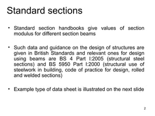
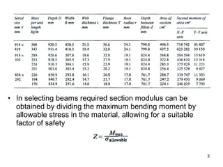
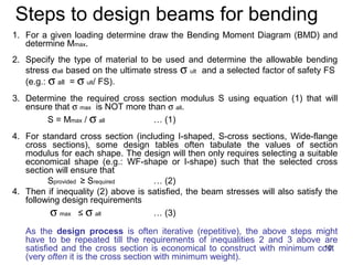
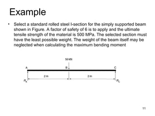
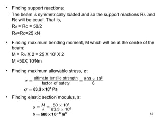
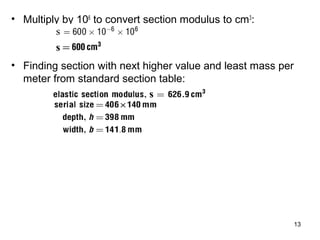

This document discusses the selection and design of standard steel beams and columns. It provides information on: 1) How to select standard steel sections from reference tables that list section properties like elastic section modulus. 2) How to calculate required section modulus based on maximum bending moment and allowable stress. 3) Guidelines for selecting sections, including choosing sections that minimize weight for beams and have slenderness ratios below 180 for columns. 4) An example of designing a simply supported beam by calculating bending moment, allowable stress, and required section modulus.