1. The document discusses various engine auxiliary systems including carburetors, ignition systems, fuel injection systems, and their components and workings.
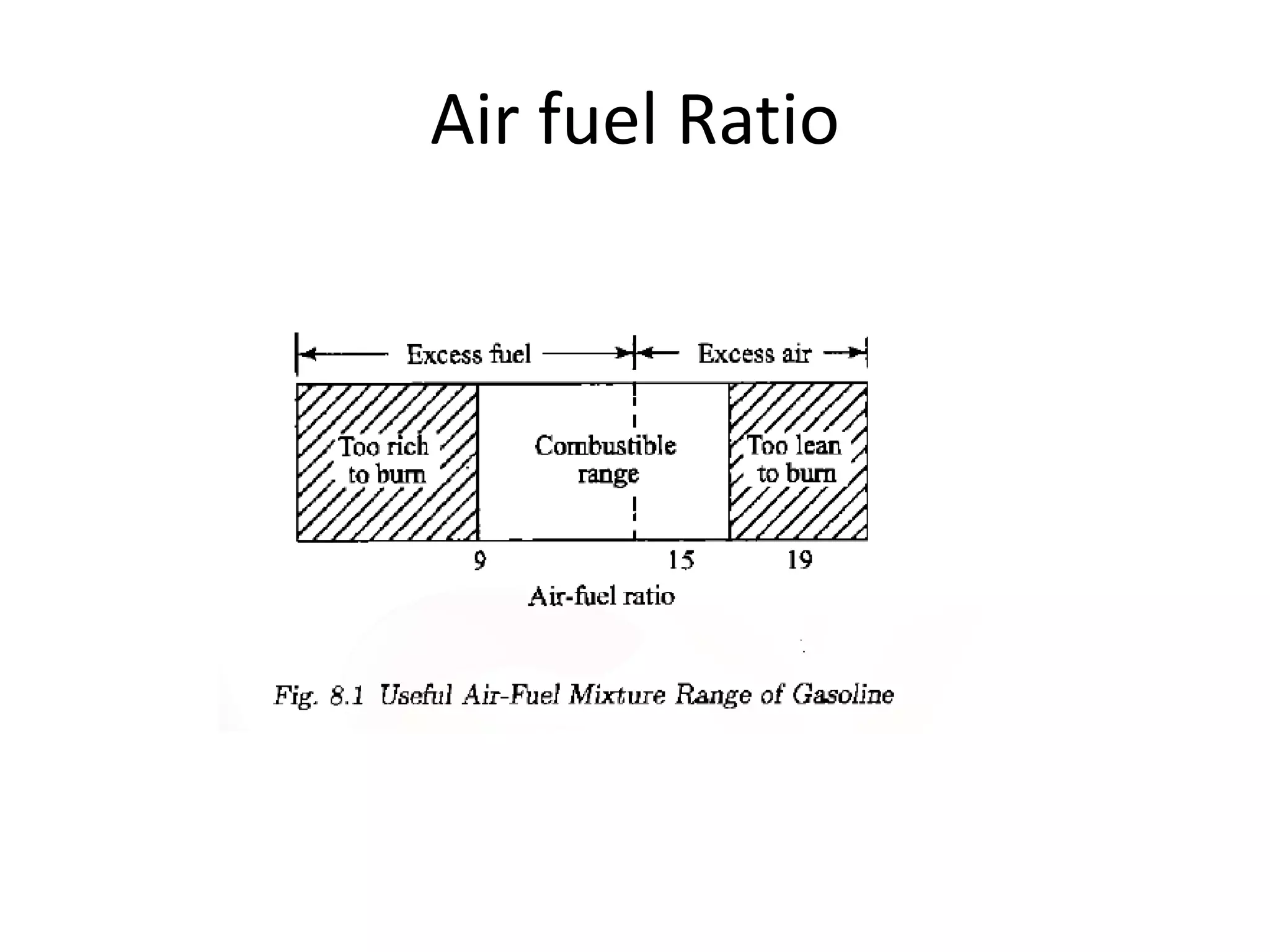
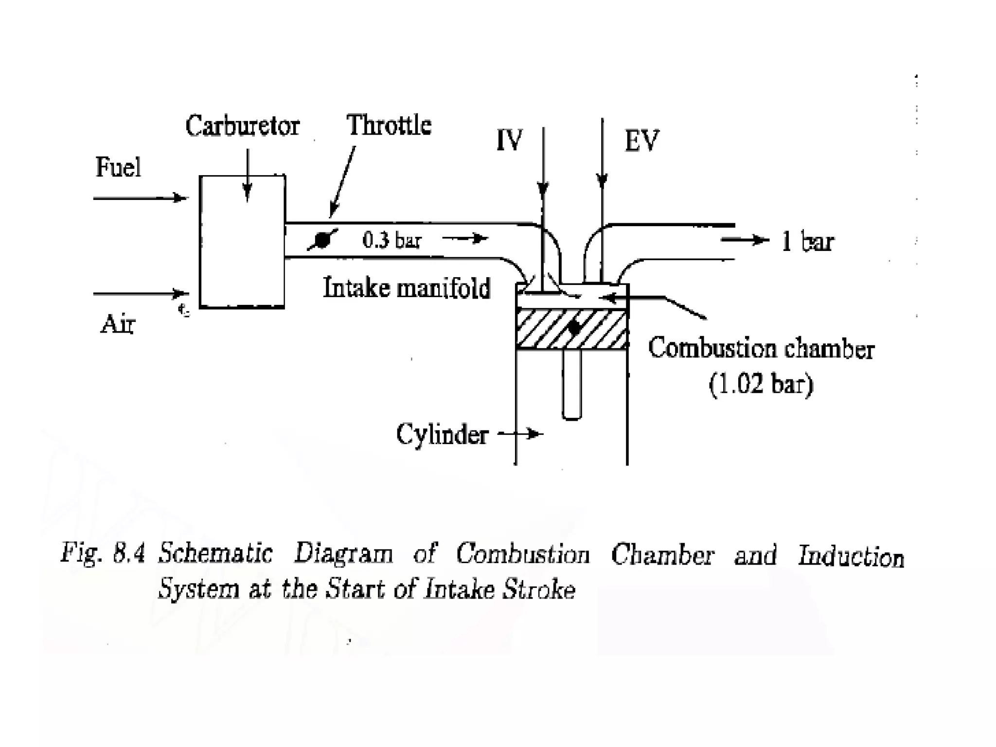
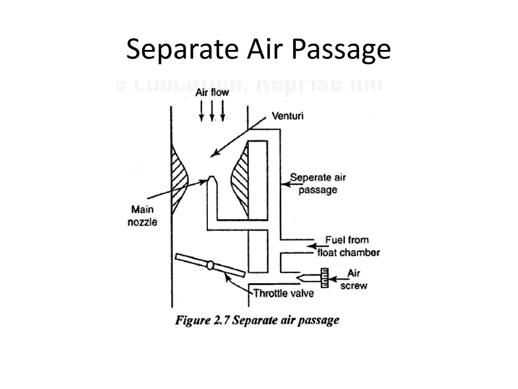
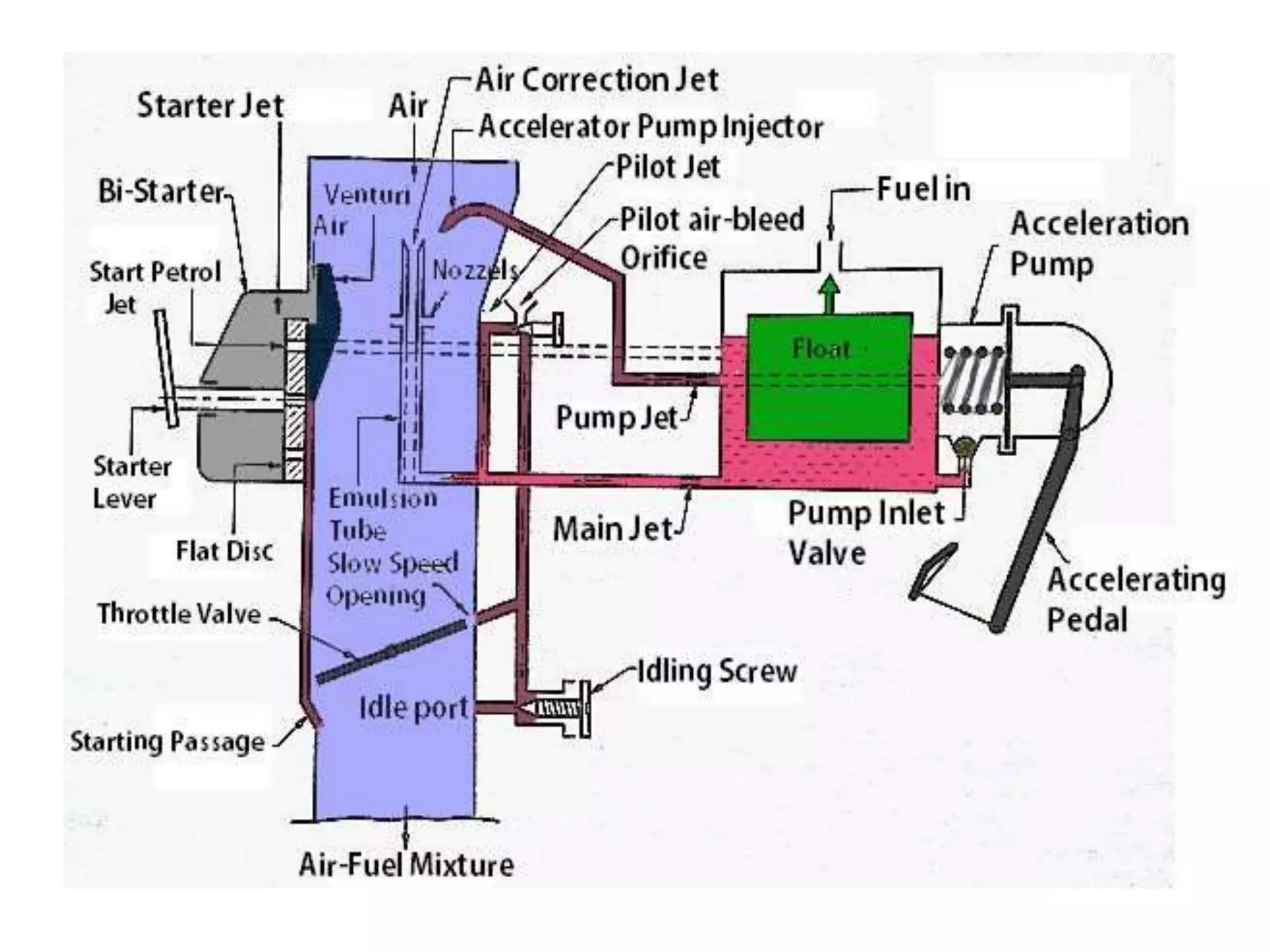
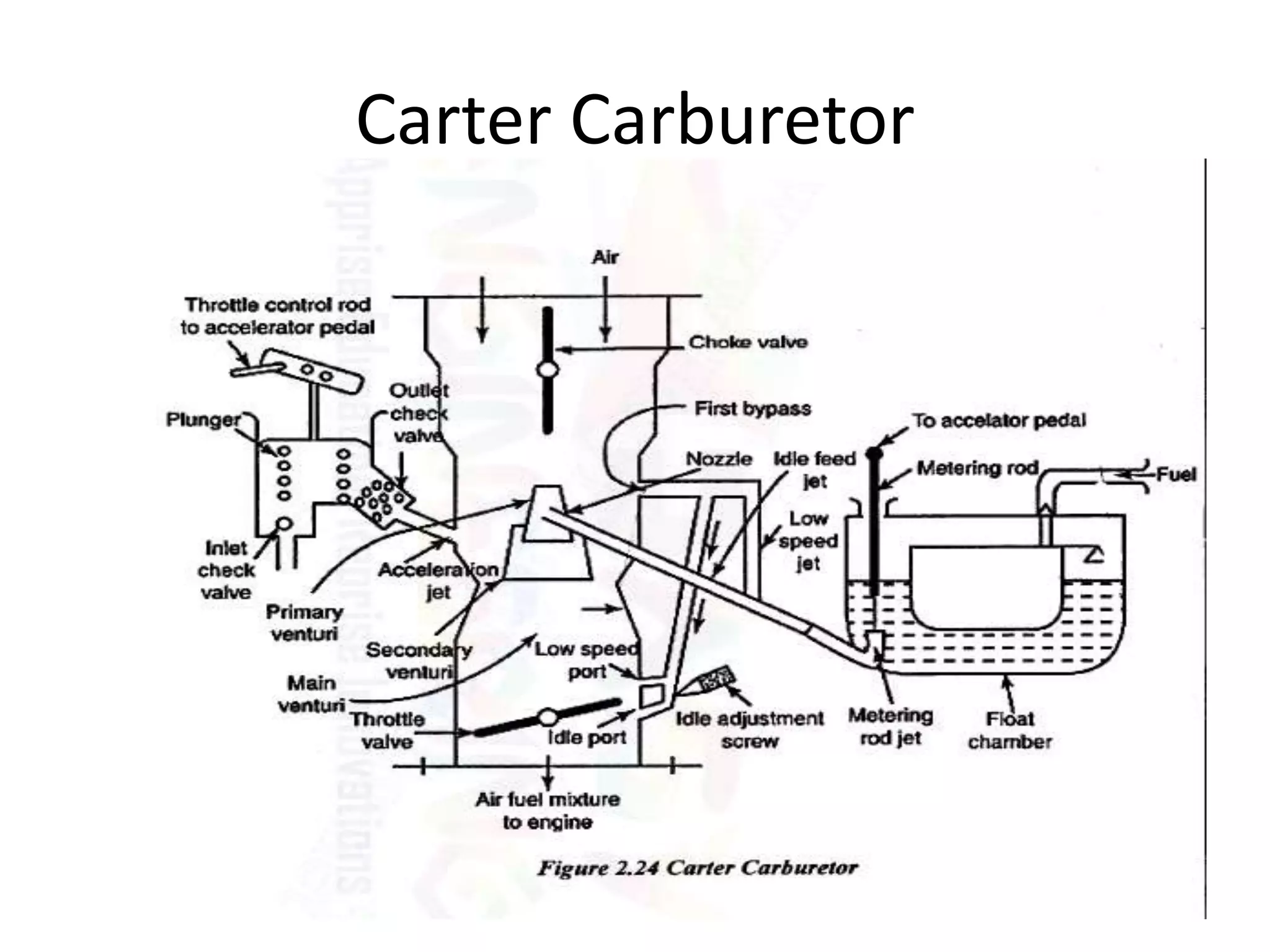
2. It describes the types and parts of carburetors like the float chamber and venturi, as well as defects like improper air-fuel mixtures at different speeds.
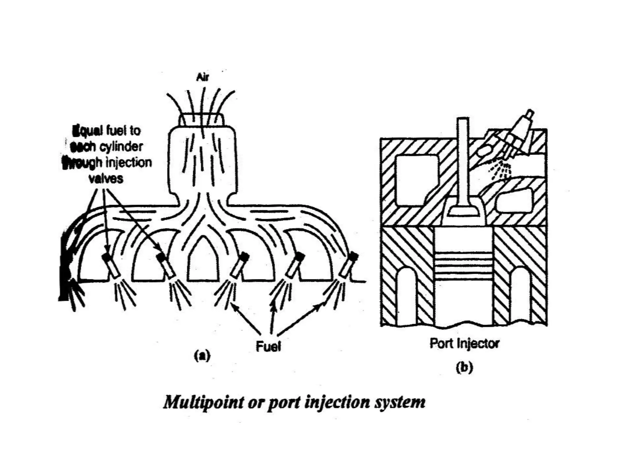
3. Electronic fuel injection systems and their sensors that allow for precise fuel delivery controlled by an electronic control unit are also covered.