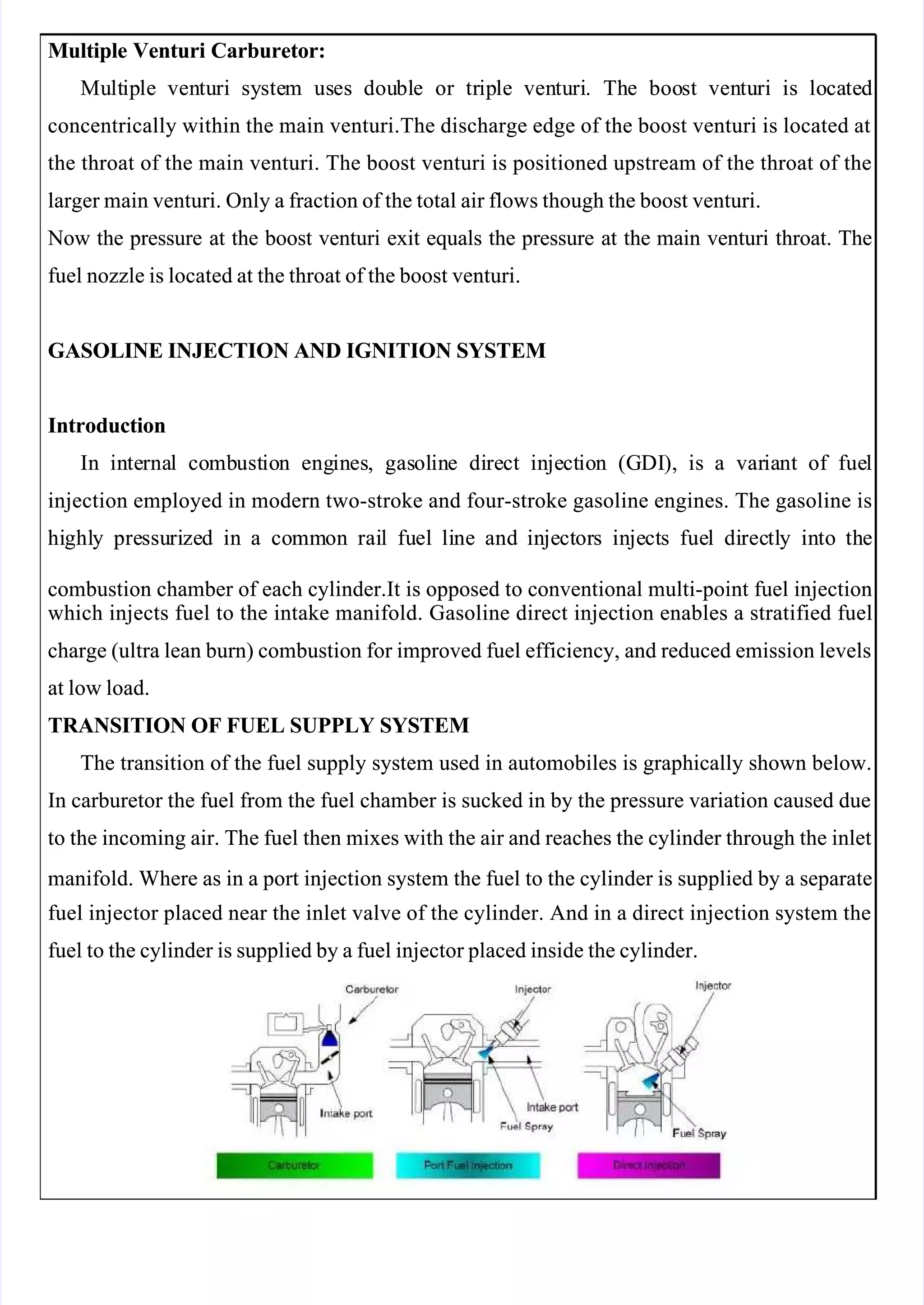
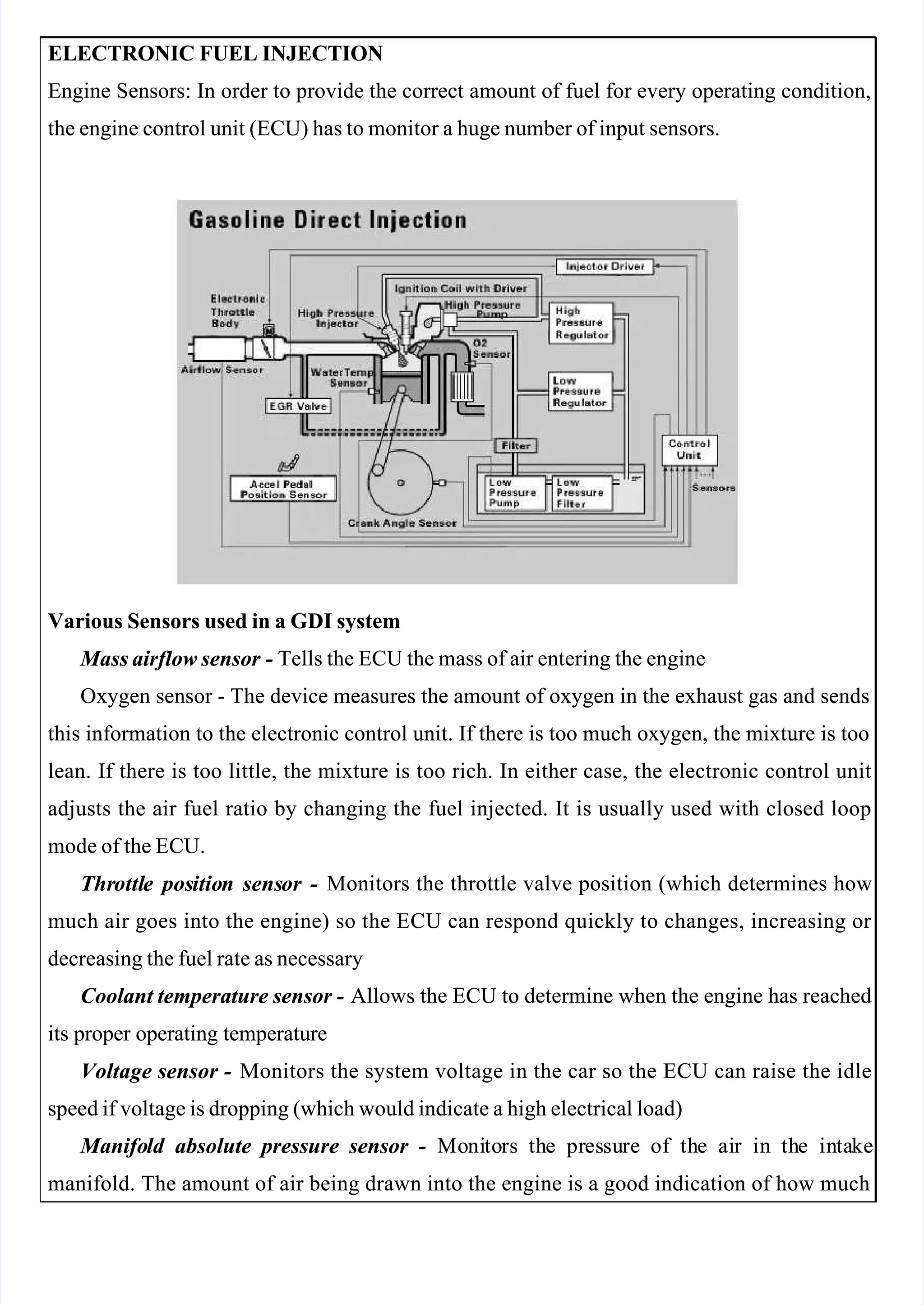
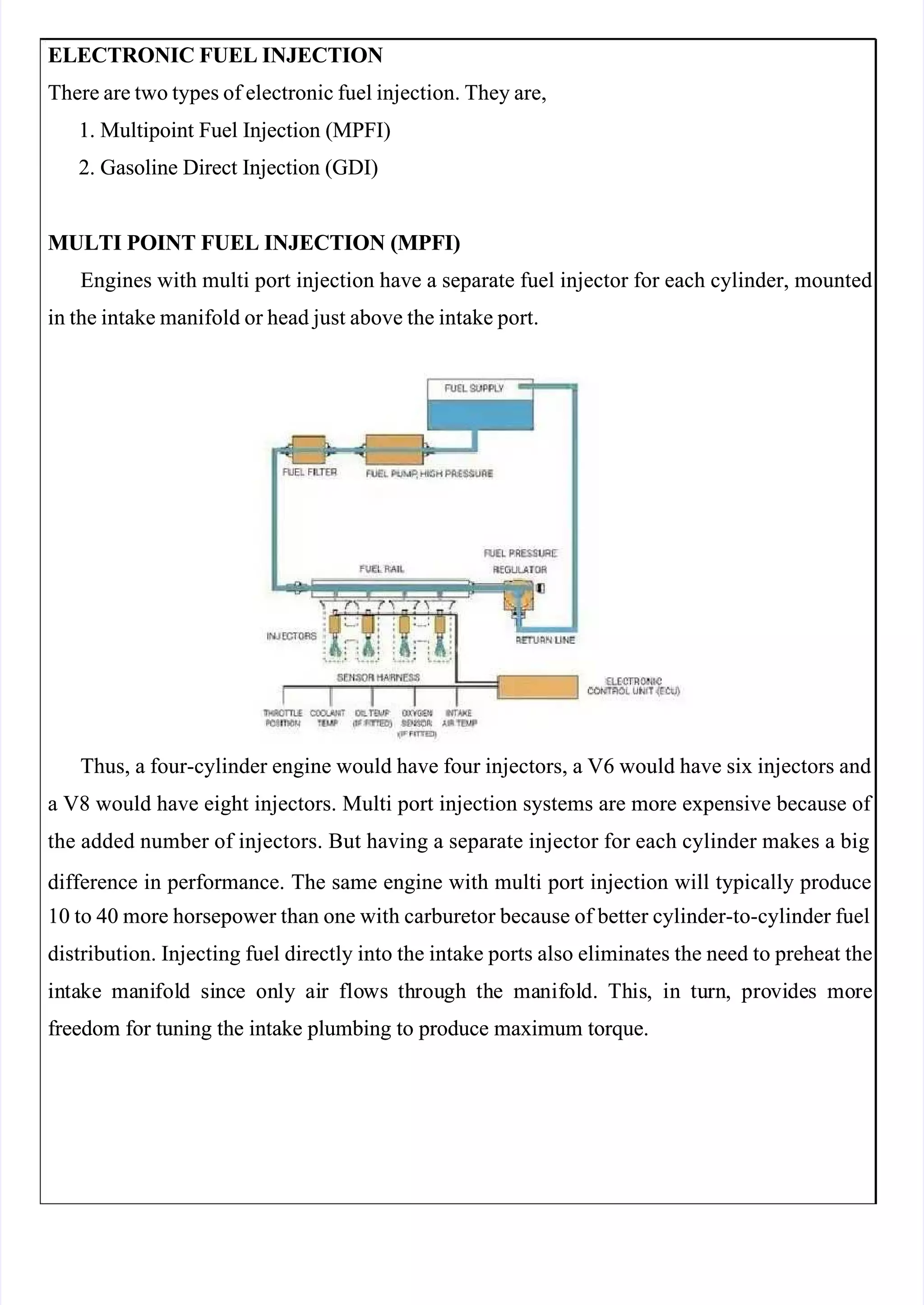
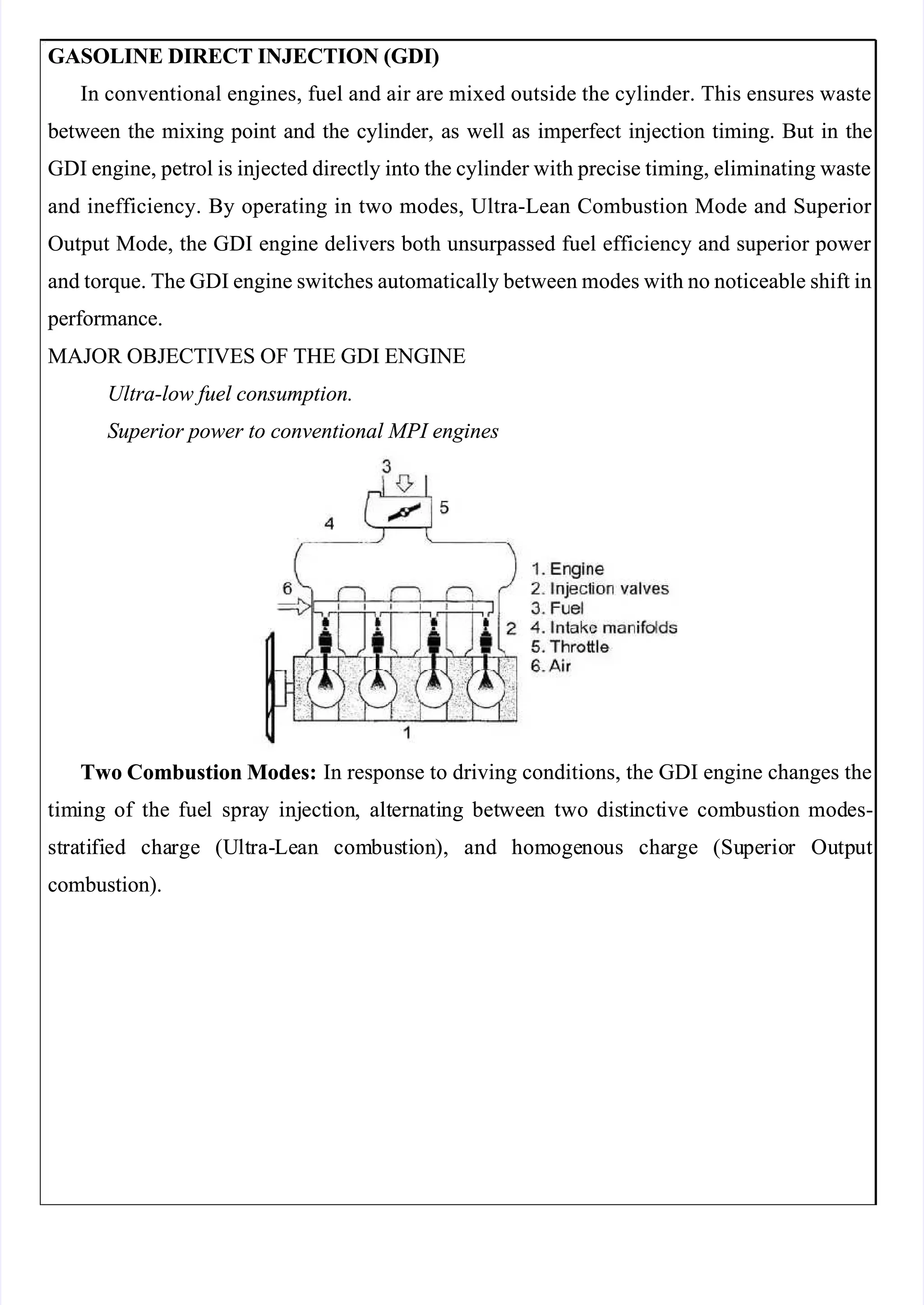
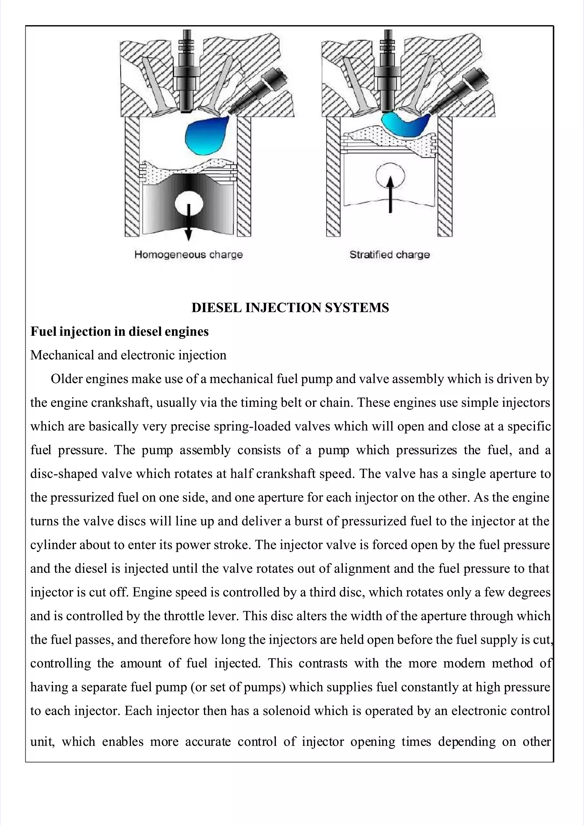
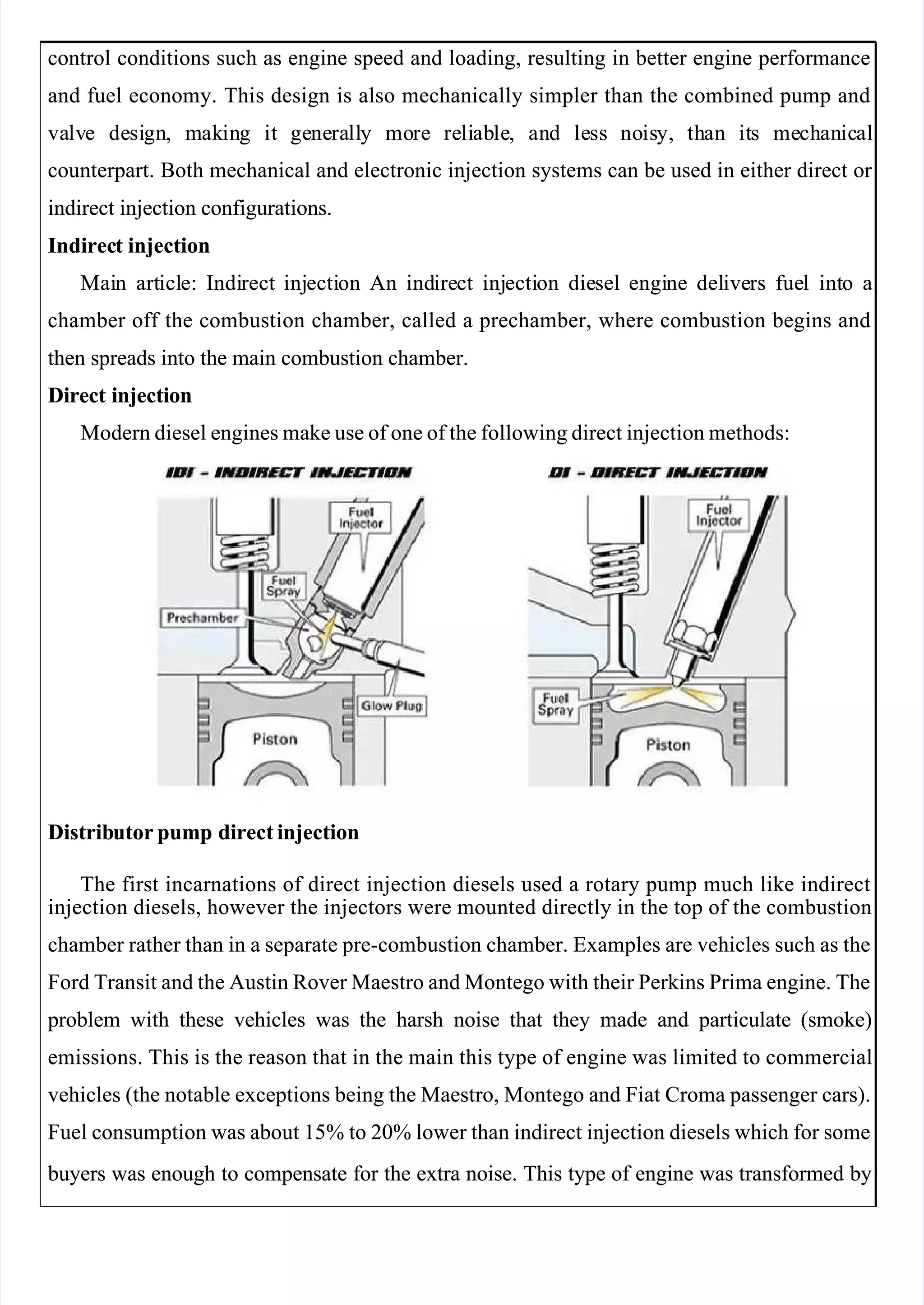
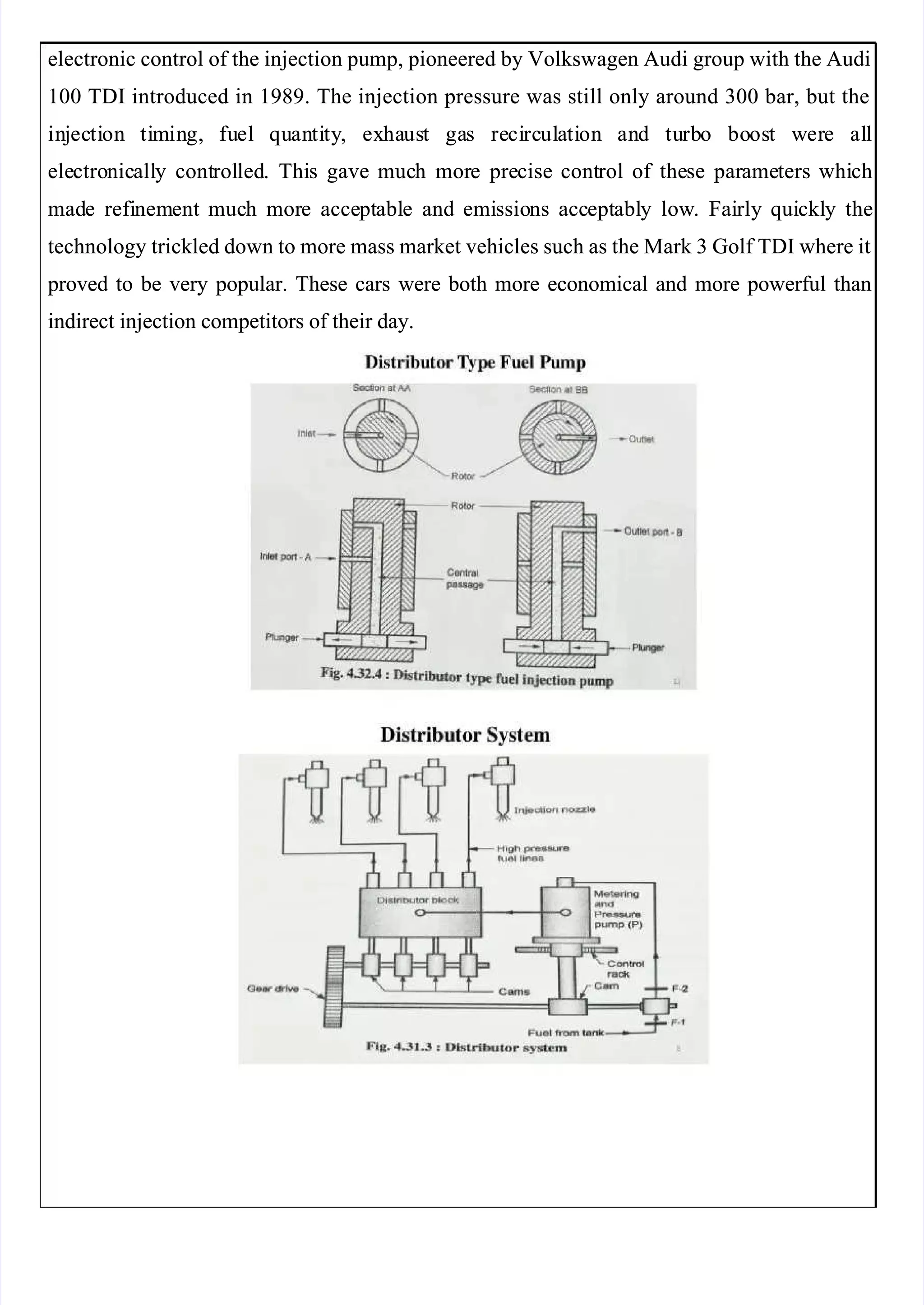
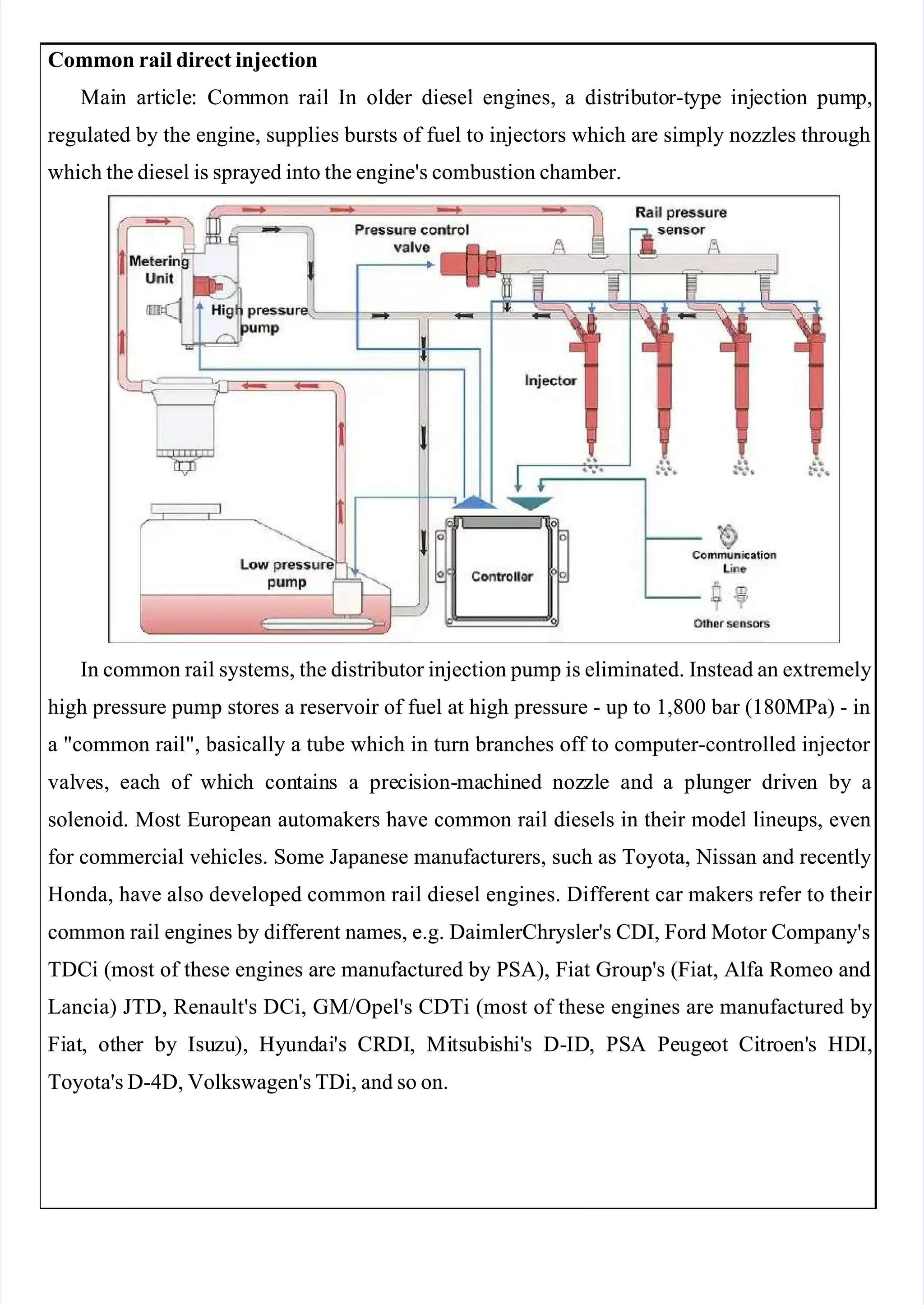
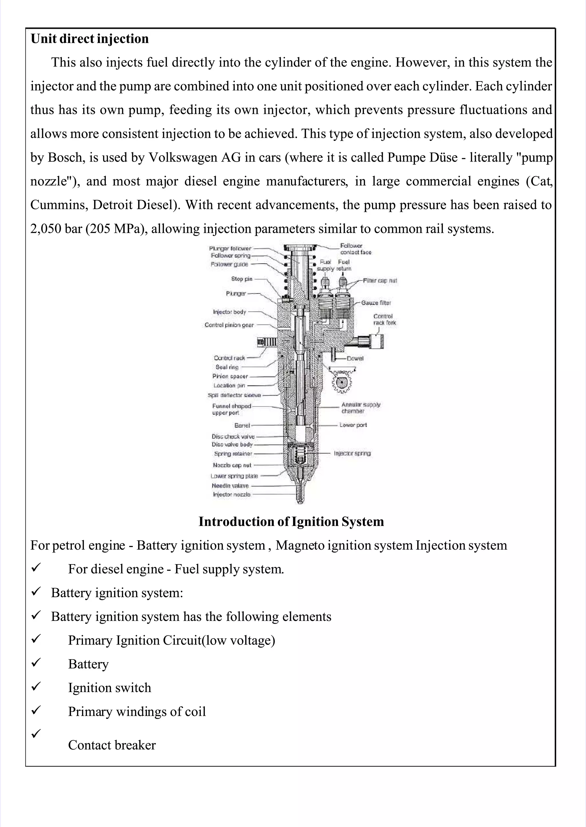
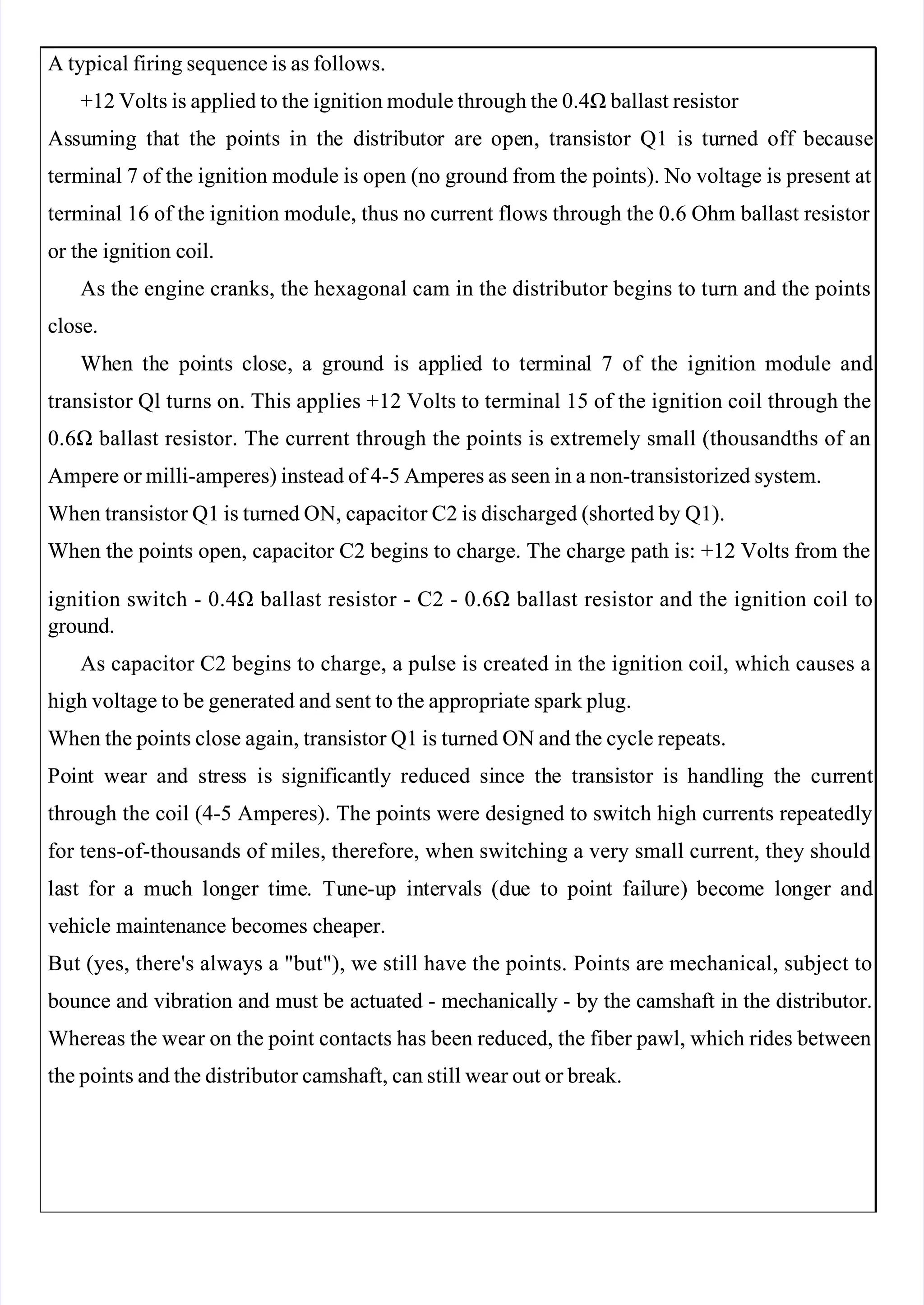
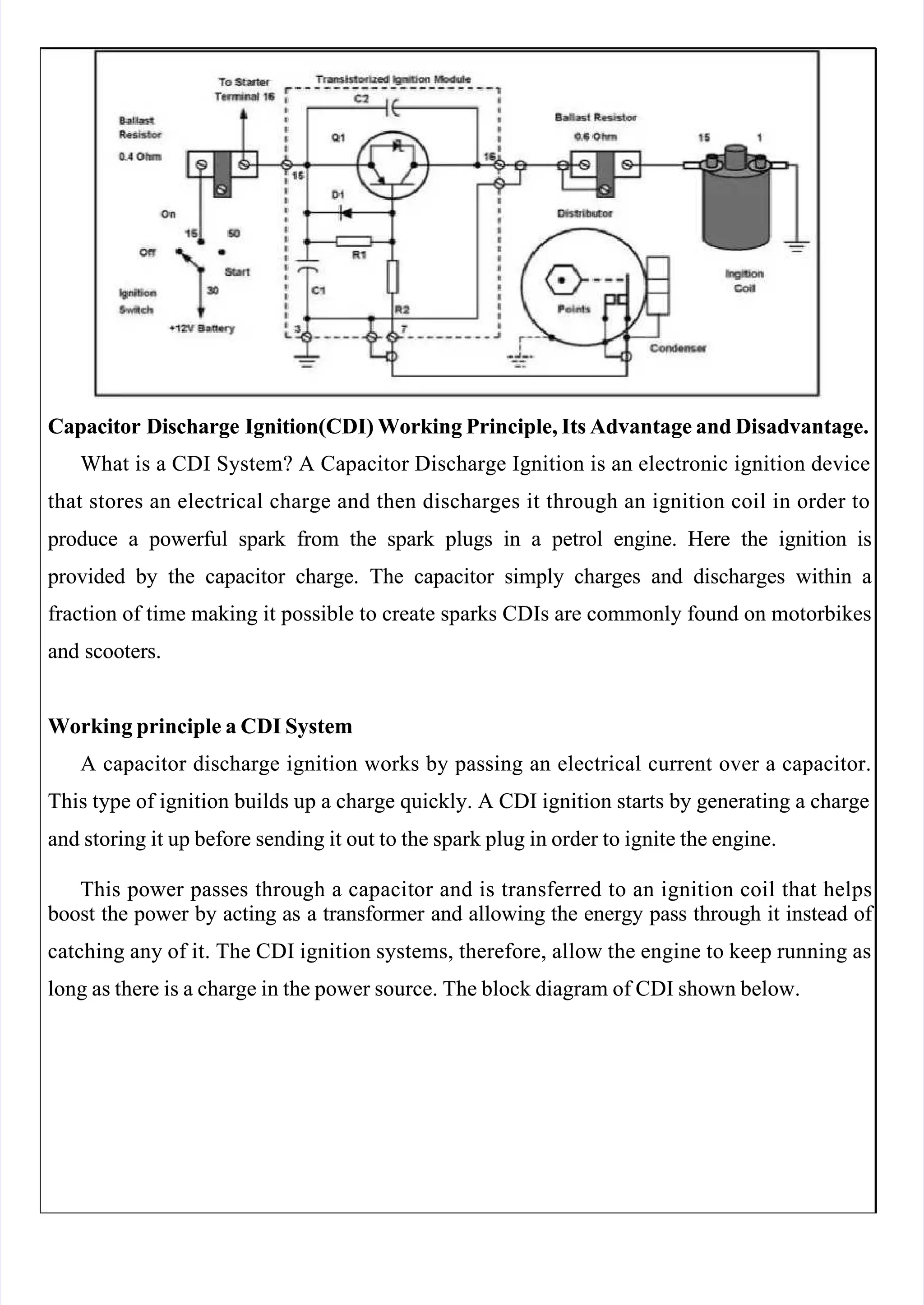
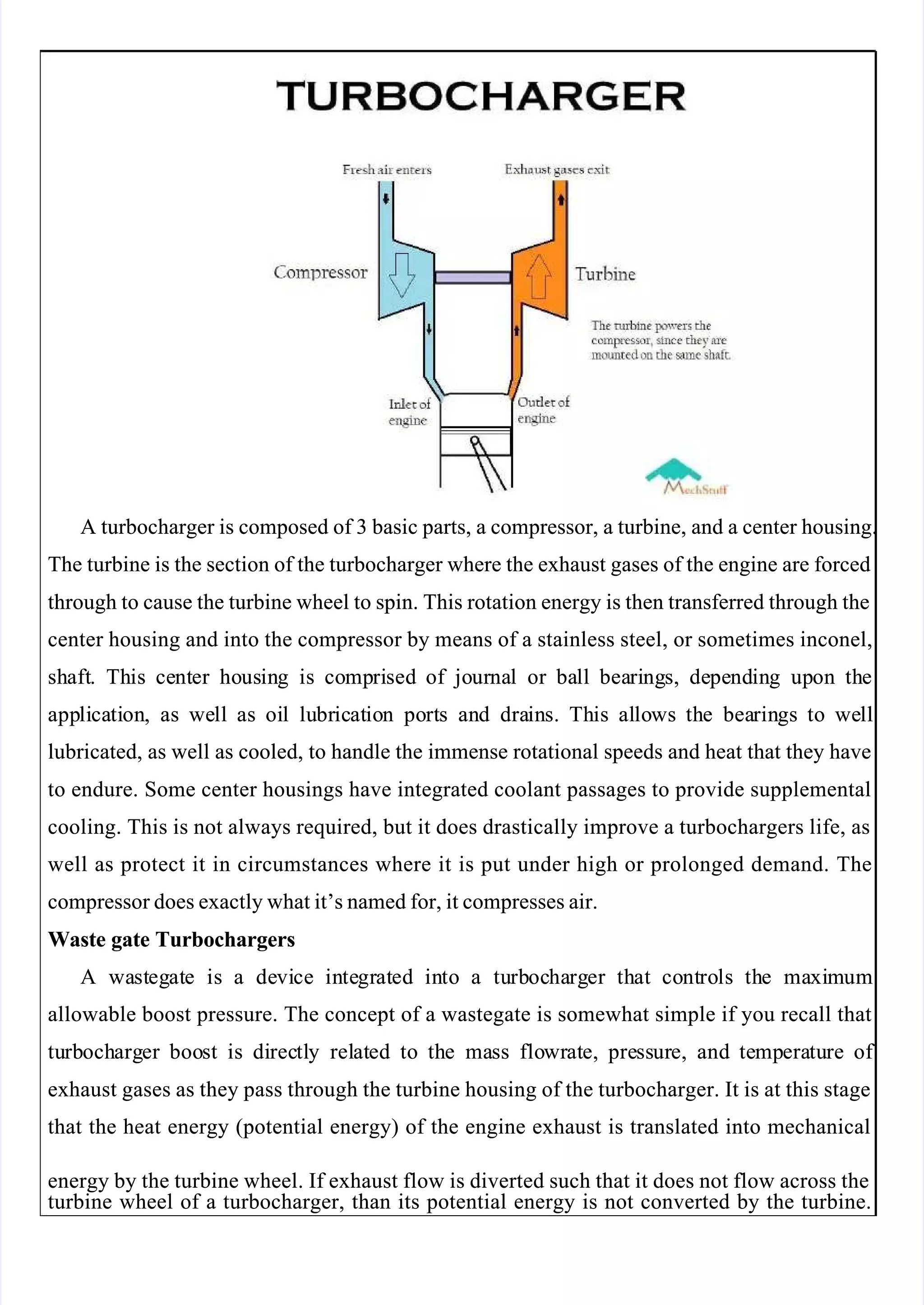
Electronically controlled gasoline injection systems provide more precise fuel delivery compared to carbureted systems. They allow for stratified fuel charge combustion for improved efficiency and reduced emissions. Common types include multi-point port injection and direct injection into the combustion chamber. While carbureted systems struggle with uneven fuel distribution among cylinders and icing, fuel injection systems inject exact amounts of fuel directly into each cylinder port or combustion chamber for uniform air-fuel ratios.