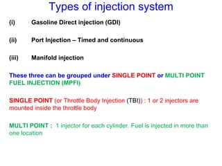
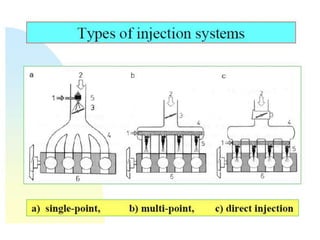
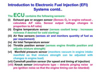
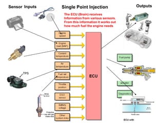
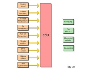
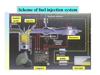
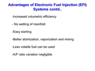
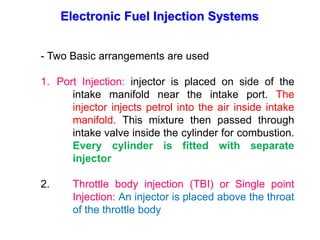
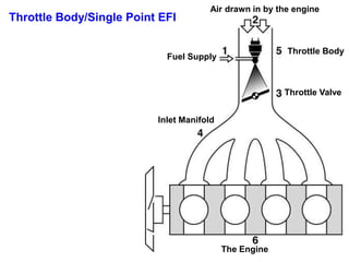
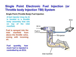
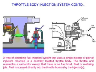
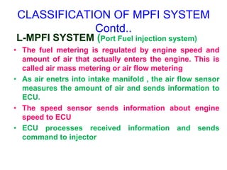
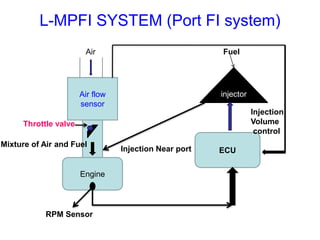
SlideShare a Scribd company logo
Electronic Fuel Injection (EFI) SYSTEM
SI ENGINE – EFI : TBI and MPFI
BY
S K Singh
Centre for Energy Studies
IIT Delhi
LIMITATIONS OF CARBURETTOR
-Non Uniform Mixture In Multi Cylinder Engines
- Accumulation Of Fuel In Manifolds So Uneven Mixture Distribution
- Rich Mixture Enters At End Cylinders And Leaner Mixture At
Cylinders near To Carburettor !!!
NEED OF ELECTRONIC FUEL
INJECTION (EFI)!!
- For uniform distribution of fuel in multi cylinder engines
- To Improve volumetric efficiency
- To prevent loss of fuel in scavenging in 2 stroke engines
Types of injection system
(i) Gasoline Direct injection (GDI)
(ii) Port Injection – Timed and continuous
(iii) Manifold injection
These three can be grouped under SINGLE POINT or MULTI POINT
FUEL INJECTION (MPFI)
SINGLE POINT (or Throttle Body Injection (TBI)) : 1 or 2 injectors are
mounted inside the throttle body
MULTI POINT : 1 injector for each cylinder. Fuel is injected in more than
one location
Types of injection system contd..
(i) Continuous injection : Uses a rotary pump (creates 0.75 to 1.5
bar pressure). Timing and duration of injection is determined
by ECU
(ii) Timed injection: A fuel supply pump supplies fuel at around 2
bar pressure when engine runs at maximum speed . Also
fitted with an Injection pump and nozzle.
Nozzle injection pressure:
- At port 6.5 bar
- Inside combustion chamber 16 to 35 bar
Basic components of injection system
-Pumping element
-Metering element
-Mixing element
-Metering control
-Mixture control
-Distributing element
-Timing control
-Ambient Control
Introduction to Electronic Petrol
Throttle/Single Point Fuel Injection Systems
The Carburettor has now been replaced with petrol injection systems.
These systems supply the engine with a highly atomized mixture of air
and fuel in the correct air/fuel ratio. This has the following advantages
over the carburettor systems
Lower exhaust emissions (pollution)
Better fuel consumption
Smoother engine operation and greater power
Automatic adjustment of the air/fuel ratio to keep the vehicles
Electronic Fuel Injector
Needle valve
Electrical connector
Fuel filter
Fuel in
Spring
Armature
Nozzle/jet
Solenoid coil
Electronic Fuel Injector Operation
An injector sprays fuel into the inlet manifold by use of a solenoid coil.
When the coil is switch on by the ECU, it pulls the armature/needle
valve away from the nozzle, allowing pressurized fuel into the engine.
When the coil is not switched on, the spring pushes the
armature/needle against the nozzle, no fuel is injected into the inlet
manifold
Injectors are more precise and
efficient than carburettors.
INJECTOR
Introduction to Electronic Fuel Injection (EFI)
Systems
Modern cars uses engine sensors, computer and solenoid
operated fuel injectors to meter and inject the right quantity of
fuel
An Electronic control Unit (ECU) or the computer receives
electrical signals in the form of current or voltage from various
sensors. It then uses the stored data to operate the injectors,
ignition system and other devices.
Introduction to Electronic Fuel Injection (EFI)
Systems contd..
The ECUcontains the following sensors:
(i) Exhaust gas or oxygen sensor (Senses O2 in engine exhaust ,
calculates A/F ratio. Sensor output voltage changes in
proportion to A/f ratio)
(ii) Engine temperature sensor (senses coolant temp : increases
richness if desired for cold starting)
(iii) Air flow sensors (senses air and monitors quantity of fuel as
per requirement)
(iv) Air Inlet Temperature sensor
(v) Throttle position sensor (senses engine throttle position and
adjusts mixture strength)
(vi) Manifold pressure sensor (monitors vacuum in engine intake
manifold so that mixture strength can be adjusted with
changes in engine load)
(vii) Camshaft position sensor (for speed and timing of injection)
(viii) Knock sensor (microphone type – detects pinging noise or
pre ignition noise so that the engine timing can be retarded)
Heating
element
Sensor
element
Protective
cap with gas
intake slots
Wires
to ECU
Heating
element
Sensor
element
Protective
cap with gas
intake slots
Wires
to ECU
Reference
voltage
Engine coolant
temperature sensor
+V
V
0V

Reference
voltage
Reference
voltage
Engine coolant
temperature sensor
+V
V
0V

+5V
0V
TPS
+5V
0V
TPS
TPS
ECU
IAC valve
Throttle valve
Air in
Solenoid coil
ECU
IAC valve
Throttle valve
Air in
Solenoid coil
The ECU (Brain) receives
Information from various sensors.
From this information it works out
how much fuel the engine needs
Inputs Outputs
Single Point Injection
Sensor
Advantages of Electronic Fuel Injection (EFI)
Systems contd..
-Increased volumetric efficiency
- No wetting of manifold
-Easy starting
-Better atomization, vaporization and mixing
-Less volatile fuel can be used
-A/F ratio variation negligible
Limitations of Electronic Fuel Injection (EFI)
Systems contd..
- High Initial cost
-High Maintenance cost
- Servicing problems
- Sensors problems
Electronic Fuel Injection Systems
- Two Basic arrangements are used
1. Port Injection: injector is placed on side of the
intake manifold near the intake port. The
injector injects petrol into the air inside intake
manifold. This mixture then passed through
intake valve inside the cylinder for combustion.
Every cylinder is fitted with separate
injector
2. Throttle body injection (TBI) or Single point
Injection: An injector is placed above the throat
of the throttle body
Air drawn in by the engine
Fuel Supply
Throttle Body
Throttle Valve
Inlet Manifold
The Engine
Throttle Body/Single Point EFI
Single Point Electronic Fuel Injection (or
Throttle body Injection TBI) System
A fuel injector (may be 2)
is located in a throttle
body assembly that sits
on top of the inlet
manifold.
Fuel is sprayed into the
inlet manifold from
above the throttle valve,
mixing with incoming
air.
Fuel quantity, how
much fuel is injected is
controlled by an ECU.
Single Point (Throttle Body) Fuel Injection
ECU
Fuel in
Inlet manifold
Air in
TB injector
Throttle Body Injection contd..
• The throttle body injection (TBI) system uses one or two injector valves mounted in a
throttle body assembly. The injectors spray fuel into the top of the throttle body air horn
The TBI fuel spray mixes with the air flowing through the air horn. The mixture is
then pulled into the engine by intake manifold vacuum. The throttle body injection
assembly typically consists of the following: throttle body housing, fuel injectors, fuel
pressure regulator, throttle positioner, throttle position sensor, and throttle plates.
• The THROTTLE BODY housing, like a carburetor body, bolts to the pad on the
intake manifold. It houses the metal castings that hold the injectors, the fuel pressure
regulator, and the throttle plates. The throttle plates are located in the lower section of
the body. A linkage or cable connects the throttle plates with the accelerator pedal. An
inlet fuel line and outlet return line connects to the fittings on the body.
THROTTLE BODY INJECTION SYSTEM CONTD..
A type of electronic fuel injection system that uses a single injector or pair of
injectors mounted in a centrally located throttle body. The throttle unit
resembles a carburetor except that there is no fuel bowl, float or metering
jets. Fuel is sprayed directly into the throttle bore(s) by the injector(s).
EXAMPLE OF THROTTLE BODY INDIRECT MPI AND
DIRECT MPI INJECTION SYSTEM
Multi-Point Fuel Injection MPFI
SYSTEM
1. Port Injection
In this the injector is placed on the side of the intake manifold near the intake
manifold
Air drawn in by the engine
Fuel Injectors
Throttle Valve
Fuel
Supply
Inlet Manifold
Injectors
Engine
Multi – Point S.I. Fuel Injection
M.P.F.I. System
• M.P.F.I. means Multi Point Fuel Injection system. In this system each
cylinder has number of injectors to supply/spray fuel in the
cylinders as compared to one injector located centrally to
supply/spray fuel in case of single point injection system.
Multi-point fuel injection injects fuel into the intake port just
upstream of the cylinder's intake valve, rather than at a central point
within an intake manifold. MPFI (or just MPI) systems can be:
SEQUENTIAL, in which injection is timed to coincide with each
cylinder's intake stroke, BATCHED, in which fuel is injected to the
cylinders in groups, without precise synchronization to any
particular cylinder's intake stroke, or SIMULTANEOUS, in which fuel
is injected at the same time to all the cylinders.
Many modern EFI systems utilize sequential MPFI; however, it is
beginning to be replaced by direct injection systems in newer gasoline
engines.
1. More uniform A/F mixture will be supplied to each
cylinder, hence the difference in power developed in
each cylinder is minimum. Vibration from the engine
equipped with this system is less, due to this the life of
engine components is improved.
2. No need to crank the engine twice or thrice in case of
cold starting as happens in the carburetor system.
3. Immediate response, in case of sudden acceleration
/deceleration.
4. Since the engine is controlled by ECM* (Engine Control
Module), more accurate amount of A/F mixture will be
supplied and as a result complete combustion will take
place. This leads to effective utilization of fuel supplied and
hence low emission level.
The mileage of the vehicle will be improved.
Advantage of M. P. F. I. System
CLASSIFICATION OF MPFI SYSTEM
(i) D-MPFI SYSTEM & (ii) L-MPFI SYSTEM
• D MPFI SYSTEM: (Manifold Fuel injection system)
• Vacuum in intake manifold is first sensed and also
senses volume of air by its density.
• As air enters into the intake manifold, the manifold
pressure sensor detects intake manifold vacuum and
sends information to ECU.
• Speed sensor - sends information about engine RPM
to ECU
• ECU regulates the amount of fuel supply – injector
sprays fuel in intake manifold
D-MPFI SYSTEM (Manifold FI system)
Inlet
manifold
vacuum
sensor
Engine
Air
Mixture of Air and Fuel
RPM Sensor
ECU
injector
Injection into intake
manifold
Injection
Volume
control
Fuel
CLASSIFICATION OF MPFI SYSTEM
Contd..
L-MPFI SYSTEM (Port Fuel injection system)
• The fuel metering is regulated by engine speed and
amount of air that actually enters the engine. This is
called air mass metering or air flow metering
• As air enetrs into intake manifold , the air flow sensor
measures the amount of air and sends information to
ECU.
• The speed sensor sends information about engine
speed to ECU
• ECU processes received information and sends
command to injector
Air flow
sensor
Engine
Air
Mixture of Air and Fuel
RPM Sensor
ECU
injector
Injection Near port
Injection
Volume
control
Fuel
L-MPFI SYSTEM (Port FI system)
Throttle valve

More Related Content

What's hot

Carburetor parts and working
Carburetor parts and workingCarburetor parts and working
Carburetor parts and working
Shahid Akram
 
Electronic fuel injection system [EFI]
Electronic fuel injection system [EFI]Electronic fuel injection system [EFI]
Electronic fuel injection system [EFI]
Zia ur rahman
 
Single point injection
Single point injectionSingle point injection
Single point injection
Mweyi1
 
Mpfi ppt
Mpfi pptMpfi ppt
Basic of engine
Basic of engineBasic of engine
Basic of engine
Sriram Karunanithi
 
CI engine
CI engineCI engine
CI engine
sachin chaurasia
 
COMMON RAIL DIESEL INJECTION (CRDI;CRDe)
COMMON RAIL DIESEL INJECTION (CRDI;CRDe)COMMON RAIL DIESEL INJECTION (CRDI;CRDe)
COMMON RAIL DIESEL INJECTION (CRDI;CRDe)
Ananda Murugan M
 
COMBUSTION IN S I & C I ENGINES
COMBUSTION IN S I & C I ENGINESCOMBUSTION IN S I & C I ENGINES
COMBUSTION IN S I & C I ENGINES
Jim Alex
 
Automobile engineering - FUEL SUPPLY SYSTEM
Automobile engineering - FUEL SUPPLY SYSTEMAutomobile engineering - FUEL SUPPLY SYSTEM
Automobile engineering - FUEL SUPPLY SYSTEM
Altamash Ali
 
MULTI-POINT FUEL INJECTION SYSTEM
MULTI-POINT FUEL INJECTION SYSTEMMULTI-POINT FUEL INJECTION SYSTEM
MULTI-POINT FUEL INJECTION SYSTEM
Mihir Patel
 
Electronic fuel injection system
Electronic fuel injection system Electronic fuel injection system
Electronic fuel injection system
Damian Castelino
 
Carburetor Theory
Carburetor TheoryCarburetor Theory
Carburetor TheoryJ.T.A.JONES
 
mpfi system ppt
mpfi system pptmpfi system ppt
mpfi system ppt
Kumar Gaurav
 
Basics of IC engine
Basics of IC engineBasics of IC engine
Basics of IC engineSLA1987
 
Stages of combustion
Stages of combustionStages of combustion
Stages of combustion
Rahul Sam
 
Carburetion and fuel injection
Carburetion and fuel injectionCarburetion and fuel injection
Carburetion and fuel injection
Manish Singh
 
Testing and performance of IC engine
Testing and performance of IC engineTesting and performance of IC engine
Testing and performance of IC engine
Mustafa Bzu
 
Fuel Injection Systems
Fuel Injection SystemsFuel Injection Systems
Fuel Injection Systems
Rajat Seth
 
2 fuel-supply-systems
2 fuel-supply-systems2 fuel-supply-systems
2 fuel-supply-systems
Narender Kumar
 

What's hot (20)

Carburetor parts and working
Carburetor parts and workingCarburetor parts and working
Carburetor parts and working
 
Electronic fuel injection system [EFI]
Electronic fuel injection system [EFI]Electronic fuel injection system [EFI]
Electronic fuel injection system [EFI]
 
Carburetors types
Carburetors typesCarburetors types
Carburetors types
 
Single point injection
Single point injectionSingle point injection
Single point injection
 
Mpfi ppt
Mpfi pptMpfi ppt
Mpfi ppt
 
Basic of engine
Basic of engineBasic of engine
Basic of engine
 
CI engine
CI engineCI engine
CI engine
 
COMMON RAIL DIESEL INJECTION (CRDI;CRDe)
COMMON RAIL DIESEL INJECTION (CRDI;CRDe)COMMON RAIL DIESEL INJECTION (CRDI;CRDe)
COMMON RAIL DIESEL INJECTION (CRDI;CRDe)
 
COMBUSTION IN S I & C I ENGINES
COMBUSTION IN S I & C I ENGINESCOMBUSTION IN S I & C I ENGINES
COMBUSTION IN S I & C I ENGINES
 
Automobile engineering - FUEL SUPPLY SYSTEM
Automobile engineering - FUEL SUPPLY SYSTEMAutomobile engineering - FUEL SUPPLY SYSTEM
Automobile engineering - FUEL SUPPLY SYSTEM
 
MULTI-POINT FUEL INJECTION SYSTEM
MULTI-POINT FUEL INJECTION SYSTEMMULTI-POINT FUEL INJECTION SYSTEM
MULTI-POINT FUEL INJECTION SYSTEM
 
Electronic fuel injection system
Electronic fuel injection system Electronic fuel injection system
Electronic fuel injection system
 
Carburetor Theory
Carburetor TheoryCarburetor Theory
Carburetor Theory
 
mpfi system ppt
mpfi system pptmpfi system ppt
mpfi system ppt
 
Basics of IC engine
Basics of IC engineBasics of IC engine
Basics of IC engine
 
Stages of combustion
Stages of combustionStages of combustion
Stages of combustion
 
Carburetion and fuel injection
Carburetion and fuel injectionCarburetion and fuel injection
Carburetion and fuel injection
 
Testing and performance of IC engine
Testing and performance of IC engineTesting and performance of IC engine
Testing and performance of IC engine
 
Fuel Injection Systems
Fuel Injection SystemsFuel Injection Systems
Fuel Injection Systems
 
2 fuel-supply-systems
2 fuel-supply-systems2 fuel-supply-systems
2 fuel-supply-systems
 

Similar to EFI system

ELECTRONIC FUEL INJECTOR
ELECTRONIC FUEL INJECTORELECTRONIC FUEL INJECTOR
ELECTRONIC FUEL INJECTOR
Debashish Bose
 
Fuel injection in si engine by shubham sanjay sorate ph.no.8421592224
Fuel injection in si engine by shubham sanjay sorate ph.no.8421592224Fuel injection in si engine by shubham sanjay sorate ph.no.8421592224
Fuel injection in si engine by shubham sanjay sorate ph.no.8421592224
8421592224
 
Automobile unit 2 Engine Auxiliary Systems
Automobile unit 2   Engine Auxiliary SystemsAutomobile unit 2   Engine Auxiliary Systems
Automobile unit 2 Engine Auxiliary Systems
RMK College of Engineering and Technology
 
UNIT-II-ENGINE AUXILIARY SYSTEMS.pptx
UNIT-II-ENGINE AUXILIARY SYSTEMS.pptxUNIT-II-ENGINE AUXILIARY SYSTEMS.pptx
UNIT-II-ENGINE AUXILIARY SYSTEMS.pptx
ShanmathyAR2
 
UNIT-II-ENGINE AUXILIARY SYSTEMS.pptx
UNIT-II-ENGINE AUXILIARY SYSTEMS.pptxUNIT-II-ENGINE AUXILIARY SYSTEMS.pptx
UNIT-II-ENGINE AUXILIARY SYSTEMS.pptx
prakash0712
 
Automotive engineering - How cars work
Automotive engineering - How cars workAutomotive engineering - How cars work
Automotive engineering - How cars work
Avinay Sharma
 
UNIT-II-ENGINE AUXILIARY SYSTEMS &TURBOCHARGER
UNIT-II-ENGINE AUXILIARY SYSTEMS &TURBOCHARGERUNIT-II-ENGINE AUXILIARY SYSTEMS &TURBOCHARGER
UNIT-II-ENGINE AUXILIARY SYSTEMS &TURBOCHARGER
DineshKumar4165
 
PER.pdf
PER.pdfPER.pdf
PER.pdf
VikramMagar1
 
seminar report
seminar reportseminar report
seminar report
naresh12134
 
Fuel injectors ppt
Fuel injectors pptFuel injectors ppt
Fuel injectors ppt
Tanmay Kanade
 
Halderman ch078 lecture
Halderman ch078 lectureHalderman ch078 lecture
Halderman ch078 lecturemcfalltj
 
Unit 2.pdf
Unit 2.pdfUnit 2.pdf
Unit 2.pdf
anilakumara
 
Mpfi engine
Mpfi engineMpfi engine
Mpfi engine
maheshwarai
 
Mpfi engine
Mpfi engineMpfi engine
Mpfi engine
maheshwarai
 
Fuel feed system
Fuel feed systemFuel feed system
Fuel feed system
Debarghya Chakraborty
 
MD_PRESENTATION.pdf
MD_PRESENTATION.pdfMD_PRESENTATION.pdf
MD_PRESENTATION.pdf
ankitchaudhary821764
 
Multi point fuel injection system
Multi point fuel injection systemMulti point fuel injection system
Multi point fuel injection system
VV College of engineering , Thirunelveli - 627657
 
Multi point fuel injection
Multi point fuel injectionMulti point fuel injection
Multi point fuel injection
RAVI KUMAR
 
Gasoline direct injection system
Gasoline direct injection system Gasoline direct injection system
Gasoline direct injection system
shubhambadhe5
 

Similar to EFI system (20)

EFI system
EFI systemEFI system
EFI system
 
ELECTRONIC FUEL INJECTOR
ELECTRONIC FUEL INJECTORELECTRONIC FUEL INJECTOR
ELECTRONIC FUEL INJECTOR
 
Fuel injection in si engine by shubham sanjay sorate ph.no.8421592224
Fuel injection in si engine by shubham sanjay sorate ph.no.8421592224Fuel injection in si engine by shubham sanjay sorate ph.no.8421592224
Fuel injection in si engine by shubham sanjay sorate ph.no.8421592224
 
Automobile unit 2 Engine Auxiliary Systems
Automobile unit 2   Engine Auxiliary SystemsAutomobile unit 2   Engine Auxiliary Systems
Automobile unit 2 Engine Auxiliary Systems
 
UNIT-II-ENGINE AUXILIARY SYSTEMS.pptx
UNIT-II-ENGINE AUXILIARY SYSTEMS.pptxUNIT-II-ENGINE AUXILIARY SYSTEMS.pptx
UNIT-II-ENGINE AUXILIARY SYSTEMS.pptx
 
UNIT-II-ENGINE AUXILIARY SYSTEMS.pptx
UNIT-II-ENGINE AUXILIARY SYSTEMS.pptxUNIT-II-ENGINE AUXILIARY SYSTEMS.pptx
UNIT-II-ENGINE AUXILIARY SYSTEMS.pptx
 
Automotive engineering - How cars work
Automotive engineering - How cars workAutomotive engineering - How cars work
Automotive engineering - How cars work
 
UNIT-II-ENGINE AUXILIARY SYSTEMS &TURBOCHARGER
UNIT-II-ENGINE AUXILIARY SYSTEMS &TURBOCHARGERUNIT-II-ENGINE AUXILIARY SYSTEMS &TURBOCHARGER
UNIT-II-ENGINE AUXILIARY SYSTEMS &TURBOCHARGER
 
PER.pdf
PER.pdfPER.pdf
PER.pdf
 
seminar report
seminar reportseminar report
seminar report
 
Fuel injectors ppt
Fuel injectors pptFuel injectors ppt
Fuel injectors ppt
 
Halderman ch078 lecture
Halderman ch078 lectureHalderman ch078 lecture
Halderman ch078 lecture
 
Unit 2.pdf
Unit 2.pdfUnit 2.pdf
Unit 2.pdf
 
Mpfi engine
Mpfi engineMpfi engine
Mpfi engine
 
Mpfi engine
Mpfi engineMpfi engine
Mpfi engine
 
Fuel feed system
Fuel feed systemFuel feed system
Fuel feed system
 
MD_PRESENTATION.pdf
MD_PRESENTATION.pdfMD_PRESENTATION.pdf
MD_PRESENTATION.pdf
 
Multi point fuel injection system
Multi point fuel injection systemMulti point fuel injection system
Multi point fuel injection system
 
Multi point fuel injection
Multi point fuel injectionMulti point fuel injection
Multi point fuel injection
 
Gasoline direct injection system
Gasoline direct injection system Gasoline direct injection system
Gasoline direct injection system
 

More from INDIAN INSTITUTE OF TECHNOLOGY Delhi

Intro cad cam
Intro cad camIntro cad cam
Economic theory of demand
Economic theory of demandEconomic theory of demand
Economic theory of demand
INDIAN INSTITUTE OF TECHNOLOGY Delhi
 
Concepts of economic attributes part 2
Concepts of economic attributes part 2Concepts of economic attributes part 2
Concepts of economic attributes part 2
INDIAN INSTITUTE OF TECHNOLOGY Delhi
 
Concepts of economic attributes part 1
Concepts of economic attributes part 1Concepts of economic attributes part 1
Concepts of economic attributes part 1
INDIAN INSTITUTE OF TECHNOLOGY Delhi
 
Biomass to biofuel
Biomass to biofuelBiomass to biofuel
Biomass gasification
Biomass gasificationBiomass gasification
Biomass combustion device
Biomass combustion deviceBiomass combustion device
Biomass combustion device
INDIAN INSTITUTE OF TECHNOLOGY Delhi
 
Biomass characterization
Biomass characterizationBiomass characterization
Biomass characterization
INDIAN INSTITUTE OF TECHNOLOGY Delhi
 
Biogas purifications
Biogas purificationsBiogas purifications
Bioenergy policies and future stratgies
Bioenergy policies and future stratgiesBioenergy policies and future stratgies
Bioenergy policies and future stratgies
INDIAN INSTITUTE OF TECHNOLOGY Delhi
 
Biochemical conversion process of biomass
Biochemical conversion process of biomassBiochemical conversion process of biomass
Biochemical conversion process of biomass
INDIAN INSTITUTE OF TECHNOLOGY Delhi
 
Bio mass availability and types
Bio mass availability and typesBio mass availability and types
Bio mass availability and types
INDIAN INSTITUTE OF TECHNOLOGY Delhi
 
Agro residues and their utilization
Agro residues and their utilizationAgro residues and their utilization
Agro residues and their utilization
INDIAN INSTITUTE OF TECHNOLOGY Delhi
 
Renewable energy arun k tripathi
Renewable energy arun k tripathiRenewable energy arun k tripathi
Renewable energy arun k tripathi
INDIAN INSTITUTE OF TECHNOLOGY Delhi
 
Usage of biomass for energy
Usage of biomass for energyUsage of biomass for energy
Usage of biomass for energy
INDIAN INSTITUTE OF TECHNOLOGY Delhi
 
Carburetor air-fuel ratio calculations
Carburetor air-fuel ratio calculationsCarburetor air-fuel ratio calculations
Carburetor air-fuel ratio calculations
INDIAN INSTITUTE OF TECHNOLOGY Delhi
 
4 stroke engine working principle
4 stroke engine working principle4 stroke engine working principle
4 stroke engine working principle
INDIAN INSTITUTE OF TECHNOLOGY Delhi
 

More from INDIAN INSTITUTE OF TECHNOLOGY Delhi (20)

Intro cad cam
Intro cad camIntro cad cam
Intro cad cam
 
Energy economics
Energy economicsEnergy economics
Energy economics
 
Economic theory of demand
Economic theory of demandEconomic theory of demand
Economic theory of demand
 
Concepts of economic attributes part 2
Concepts of economic attributes part 2Concepts of economic attributes part 2
Concepts of economic attributes part 2
 
Concepts of economic attributes part 1
Concepts of economic attributes part 1Concepts of economic attributes part 1
Concepts of economic attributes part 1
 
Biorefinery
BiorefineryBiorefinery
Biorefinery
 
Biomass to biofuel
Biomass to biofuelBiomass to biofuel
Biomass to biofuel
 
Biomass gasification
Biomass gasificationBiomass gasification
Biomass gasification
 
Biomass combustion device
Biomass combustion deviceBiomass combustion device
Biomass combustion device
 
Biomass characterization
Biomass characterizationBiomass characterization
Biomass characterization
 
Biogas purifications
Biogas purificationsBiogas purifications
Biogas purifications
 
Bioenergy policies and future stratgies
Bioenergy policies and future stratgiesBioenergy policies and future stratgies
Bioenergy policies and future stratgies
 
Bio cng
Bio cngBio cng
Bio cng
 
Biochemical conversion process of biomass
Biochemical conversion process of biomassBiochemical conversion process of biomass
Biochemical conversion process of biomass
 
Bio mass availability and types
Bio mass availability and typesBio mass availability and types
Bio mass availability and types
 
Agro residues and their utilization
Agro residues and their utilizationAgro residues and their utilization
Agro residues and their utilization
 
Renewable energy arun k tripathi
Renewable energy arun k tripathiRenewable energy arun k tripathi
Renewable energy arun k tripathi
 
Usage of biomass for energy
Usage of biomass for energyUsage of biomass for energy
Usage of biomass for energy
 
Carburetor air-fuel ratio calculations
Carburetor air-fuel ratio calculationsCarburetor air-fuel ratio calculations
Carburetor air-fuel ratio calculations
 
4 stroke engine working principle
4 stroke engine working principle4 stroke engine working principle
4 stroke engine working principle
 

Recently uploaded

在线办理(ANU毕业证书)澳洲国立大学毕业证录取通知书一模一样
在线办理(ANU毕业证书)澳洲国立大学毕业证录取通知书一模一样在线办理(ANU毕业证书)澳洲国立大学毕业证录取通知书一模一样
在线办理(ANU毕业证书)澳洲国立大学毕业证录取通知书一模一样
obonagu
 
Railway Signalling Principles Edition 3.pdf
Railway Signalling Principles Edition 3.pdfRailway Signalling Principles Edition 3.pdf
Railway Signalling Principles Edition 3.pdf
TeeVichai
 
TECHNICAL TRAINING MANUAL GENERAL FAMILIARIZATION COURSE
TECHNICAL TRAINING MANUAL   GENERAL FAMILIARIZATION COURSETECHNICAL TRAINING MANUAL   GENERAL FAMILIARIZATION COURSE
TECHNICAL TRAINING MANUAL GENERAL FAMILIARIZATION COURSE
DuvanRamosGarzon1
 
Industrial Training at Shahjalal Fertilizer Company Limited (SFCL)
Industrial Training at Shahjalal Fertilizer Company Limited (SFCL)Industrial Training at Shahjalal Fertilizer Company Limited (SFCL)
Industrial Training at Shahjalal Fertilizer Company Limited (SFCL)
MdTanvirMahtab2
 
NO1 Uk best vashikaran specialist in delhi vashikaran baba near me online vas...
NO1 Uk best vashikaran specialist in delhi vashikaran baba near me online vas...NO1 Uk best vashikaran specialist in delhi vashikaran baba near me online vas...
NO1 Uk best vashikaran specialist in delhi vashikaran baba near me online vas...
Amil Baba Dawood bangali
 
The Benefits and Techniques of Trenchless Pipe Repair.pdf
The Benefits and Techniques of Trenchless Pipe Repair.pdfThe Benefits and Techniques of Trenchless Pipe Repair.pdf
The Benefits and Techniques of Trenchless Pipe Repair.pdf
Pipe Restoration Solutions
 
HYDROPOWER - Hydroelectric power generation
HYDROPOWER - Hydroelectric power generationHYDROPOWER - Hydroelectric power generation
HYDROPOWER - Hydroelectric power generation
Robbie Edward Sayers
 
J.Yang, ICLR 2024, MLILAB, KAIST AI.pdf
J.Yang,  ICLR 2024, MLILAB, KAIST AI.pdfJ.Yang,  ICLR 2024, MLILAB, KAIST AI.pdf
J.Yang, ICLR 2024, MLILAB, KAIST AI.pdf
MLILAB
 
Sachpazis:Terzaghi Bearing Capacity Estimation in simple terms with Calculati...
Sachpazis:Terzaghi Bearing Capacity Estimation in simple terms with Calculati...Sachpazis:Terzaghi Bearing Capacity Estimation in simple terms with Calculati...
Sachpazis:Terzaghi Bearing Capacity Estimation in simple terms with Calculati...
Dr.Costas Sachpazis
 
LIGA(E)11111111111111111111111111111111111111111.ppt
LIGA(E)11111111111111111111111111111111111111111.pptLIGA(E)11111111111111111111111111111111111111111.ppt
LIGA(E)11111111111111111111111111111111111111111.ppt
ssuser9bd3ba
 
Immunizing Image Classifiers Against Localized Adversary Attacks
Immunizing Image Classifiers Against Localized Adversary AttacksImmunizing Image Classifiers Against Localized Adversary Attacks
Immunizing Image Classifiers Against Localized Adversary Attacks
gerogepatton
 
Event Management System Vb Net Project Report.pdf
Event Management System Vb Net  Project Report.pdfEvent Management System Vb Net  Project Report.pdf
Event Management System Vb Net Project Report.pdf
Kamal Acharya
 
block diagram and signal flow graph representation
block diagram and signal flow graph representationblock diagram and signal flow graph representation
block diagram and signal flow graph representation
Divya Somashekar
 
ASME IX(9) 2007 Full Version .pdf
ASME IX(9)  2007 Full Version       .pdfASME IX(9)  2007 Full Version       .pdf
ASME IX(9) 2007 Full Version .pdf
AhmedHussein950959
 
DESIGN A COTTON SEED SEPARATION MACHINE.docx
DESIGN A COTTON SEED SEPARATION MACHINE.docxDESIGN A COTTON SEED SEPARATION MACHINE.docx
DESIGN A COTTON SEED SEPARATION MACHINE.docx
FluxPrime1
 
Standard Reomte Control Interface - Neometrix
Standard Reomte Control Interface - NeometrixStandard Reomte Control Interface - Neometrix
Standard Reomte Control Interface - Neometrix
Neometrix_Engineering_Pvt_Ltd
 
Hybrid optimization of pumped hydro system and solar- Engr. Abdul-Azeez.pdf
Hybrid optimization of pumped hydro system and solar- Engr. Abdul-Azeez.pdfHybrid optimization of pumped hydro system and solar- Engr. Abdul-Azeez.pdf
Hybrid optimization of pumped hydro system and solar- Engr. Abdul-Azeez.pdf
fxintegritypublishin
 
Planning Of Procurement o different goods and services
Planning Of Procurement o different goods and servicesPlanning Of Procurement o different goods and services
Planning Of Procurement o different goods and services
JoytuBarua2
 
Gen AI Study Jams _ For the GDSC Leads in India.pdf
Gen AI Study Jams _ For the GDSC Leads in India.pdfGen AI Study Jams _ For the GDSC Leads in India.pdf
Gen AI Study Jams _ For the GDSC Leads in India.pdf
gdsczhcet
 
Water Industry Process Automation and Control Monthly - May 2024.pdf
Water Industry Process Automation and Control Monthly - May 2024.pdfWater Industry Process Automation and Control Monthly - May 2024.pdf
Water Industry Process Automation and Control Monthly - May 2024.pdf
Water Industry Process Automation & Control
 

Recently uploaded (20)

在线办理(ANU毕业证书)澳洲国立大学毕业证录取通知书一模一样
在线办理(ANU毕业证书)澳洲国立大学毕业证录取通知书一模一样在线办理(ANU毕业证书)澳洲国立大学毕业证录取通知书一模一样
在线办理(ANU毕业证书)澳洲国立大学毕业证录取通知书一模一样
 
Railway Signalling Principles Edition 3.pdf
Railway Signalling Principles Edition 3.pdfRailway Signalling Principles Edition 3.pdf
Railway Signalling Principles Edition 3.pdf
 
TECHNICAL TRAINING MANUAL GENERAL FAMILIARIZATION COURSE
TECHNICAL TRAINING MANUAL   GENERAL FAMILIARIZATION COURSETECHNICAL TRAINING MANUAL   GENERAL FAMILIARIZATION COURSE
TECHNICAL TRAINING MANUAL GENERAL FAMILIARIZATION COURSE
 
Industrial Training at Shahjalal Fertilizer Company Limited (SFCL)
Industrial Training at Shahjalal Fertilizer Company Limited (SFCL)Industrial Training at Shahjalal Fertilizer Company Limited (SFCL)
Industrial Training at Shahjalal Fertilizer Company Limited (SFCL)
 
NO1 Uk best vashikaran specialist in delhi vashikaran baba near me online vas...
NO1 Uk best vashikaran specialist in delhi vashikaran baba near me online vas...NO1 Uk best vashikaran specialist in delhi vashikaran baba near me online vas...
NO1 Uk best vashikaran specialist in delhi vashikaran baba near me online vas...
 
The Benefits and Techniques of Trenchless Pipe Repair.pdf
The Benefits and Techniques of Trenchless Pipe Repair.pdfThe Benefits and Techniques of Trenchless Pipe Repair.pdf
The Benefits and Techniques of Trenchless Pipe Repair.pdf
 
HYDROPOWER - Hydroelectric power generation
HYDROPOWER - Hydroelectric power generationHYDROPOWER - Hydroelectric power generation
HYDROPOWER - Hydroelectric power generation
 
J.Yang, ICLR 2024, MLILAB, KAIST AI.pdf
J.Yang,  ICLR 2024, MLILAB, KAIST AI.pdfJ.Yang,  ICLR 2024, MLILAB, KAIST AI.pdf
J.Yang, ICLR 2024, MLILAB, KAIST AI.pdf
 
Sachpazis:Terzaghi Bearing Capacity Estimation in simple terms with Calculati...
Sachpazis:Terzaghi Bearing Capacity Estimation in simple terms with Calculati...Sachpazis:Terzaghi Bearing Capacity Estimation in simple terms with Calculati...
Sachpazis:Terzaghi Bearing Capacity Estimation in simple terms with Calculati...
 
LIGA(E)11111111111111111111111111111111111111111.ppt
LIGA(E)11111111111111111111111111111111111111111.pptLIGA(E)11111111111111111111111111111111111111111.ppt
LIGA(E)11111111111111111111111111111111111111111.ppt
 
Immunizing Image Classifiers Against Localized Adversary Attacks
Immunizing Image Classifiers Against Localized Adversary AttacksImmunizing Image Classifiers Against Localized Adversary Attacks
Immunizing Image Classifiers Against Localized Adversary Attacks
 
Event Management System Vb Net Project Report.pdf
Event Management System Vb Net  Project Report.pdfEvent Management System Vb Net  Project Report.pdf
Event Management System Vb Net Project Report.pdf
 
block diagram and signal flow graph representation
block diagram and signal flow graph representationblock diagram and signal flow graph representation
block diagram and signal flow graph representation
 
ASME IX(9) 2007 Full Version .pdf
ASME IX(9)  2007 Full Version       .pdfASME IX(9)  2007 Full Version       .pdf
ASME IX(9) 2007 Full Version .pdf
 
DESIGN A COTTON SEED SEPARATION MACHINE.docx
DESIGN A COTTON SEED SEPARATION MACHINE.docxDESIGN A COTTON SEED SEPARATION MACHINE.docx
DESIGN A COTTON SEED SEPARATION MACHINE.docx
 
Standard Reomte Control Interface - Neometrix
Standard Reomte Control Interface - NeometrixStandard Reomte Control Interface - Neometrix
Standard Reomte Control Interface - Neometrix
 
Hybrid optimization of pumped hydro system and solar- Engr. Abdul-Azeez.pdf
Hybrid optimization of pumped hydro system and solar- Engr. Abdul-Azeez.pdfHybrid optimization of pumped hydro system and solar- Engr. Abdul-Azeez.pdf
Hybrid optimization of pumped hydro system and solar- Engr. Abdul-Azeez.pdf
 
Planning Of Procurement o different goods and services
Planning Of Procurement o different goods and servicesPlanning Of Procurement o different goods and services
Planning Of Procurement o different goods and services
 
Gen AI Study Jams _ For the GDSC Leads in India.pdf
Gen AI Study Jams _ For the GDSC Leads in India.pdfGen AI Study Jams _ For the GDSC Leads in India.pdf
Gen AI Study Jams _ For the GDSC Leads in India.pdf
 
Water Industry Process Automation and Control Monthly - May 2024.pdf
Water Industry Process Automation and Control Monthly - May 2024.pdfWater Industry Process Automation and Control Monthly - May 2024.pdf
Water Industry Process Automation and Control Monthly - May 2024.pdf
 

EFI system

  • 1. Electronic Fuel Injection (EFI) SYSTEM SI ENGINE – EFI : TBI and MPFI BY S K Singh Centre for Energy Studies IIT Delhi
  • 2. LIMITATIONS OF CARBURETTOR -Non Uniform Mixture In Multi Cylinder Engines - Accumulation Of Fuel In Manifolds So Uneven Mixture Distribution - Rich Mixture Enters At End Cylinders And Leaner Mixture At Cylinders near To Carburettor !!!
  • 3. NEED OF ELECTRONIC FUEL INJECTION (EFI)!! - For uniform distribution of fuel in multi cylinder engines - To Improve volumetric efficiency - To prevent loss of fuel in scavenging in 2 stroke engines
  • 4. Types of injection system (i) Gasoline Direct injection (GDI) (ii) Port Injection – Timed and continuous (iii) Manifold injection These three can be grouped under SINGLE POINT or MULTI POINT FUEL INJECTION (MPFI) SINGLE POINT (or Throttle Body Injection (TBI)) : 1 or 2 injectors are mounted inside the throttle body MULTI POINT : 1 injector for each cylinder. Fuel is injected in more than one location
  • 5.
  • 6.
  • 7.
  • 8. Types of injection system contd.. (i) Continuous injection : Uses a rotary pump (creates 0.75 to 1.5 bar pressure). Timing and duration of injection is determined by ECU (ii) Timed injection: A fuel supply pump supplies fuel at around 2 bar pressure when engine runs at maximum speed . Also fitted with an Injection pump and nozzle. Nozzle injection pressure: - At port 6.5 bar - Inside combustion chamber 16 to 35 bar
  • 9. Basic components of injection system -Pumping element -Metering element -Mixing element -Metering control -Mixture control -Distributing element -Timing control -Ambient Control
  • 10. Introduction to Electronic Petrol Throttle/Single Point Fuel Injection Systems The Carburettor has now been replaced with petrol injection systems. These systems supply the engine with a highly atomized mixture of air and fuel in the correct air/fuel ratio. This has the following advantages over the carburettor systems Lower exhaust emissions (pollution) Better fuel consumption Smoother engine operation and greater power Automatic adjustment of the air/fuel ratio to keep the vehicles Electronic Fuel Injector
  • 11. Needle valve Electrical connector Fuel filter Fuel in Spring Armature Nozzle/jet Solenoid coil Electronic Fuel Injector Operation An injector sprays fuel into the inlet manifold by use of a solenoid coil. When the coil is switch on by the ECU, it pulls the armature/needle valve away from the nozzle, allowing pressurized fuel into the engine. When the coil is not switched on, the spring pushes the armature/needle against the nozzle, no fuel is injected into the inlet manifold Injectors are more precise and efficient than carburettors.
  • 13. Introduction to Electronic Fuel Injection (EFI) Systems Modern cars uses engine sensors, computer and solenoid operated fuel injectors to meter and inject the right quantity of fuel An Electronic control Unit (ECU) or the computer receives electrical signals in the form of current or voltage from various sensors. It then uses the stored data to operate the injectors, ignition system and other devices.
  • 14. Introduction to Electronic Fuel Injection (EFI) Systems contd.. The ECUcontains the following sensors: (i) Exhaust gas or oxygen sensor (Senses O2 in engine exhaust , calculates A/F ratio. Sensor output voltage changes in proportion to A/f ratio) (ii) Engine temperature sensor (senses coolant temp : increases richness if desired for cold starting) (iii) Air flow sensors (senses air and monitors quantity of fuel as per requirement) (iv) Air Inlet Temperature sensor (v) Throttle position sensor (senses engine throttle position and adjusts mixture strength) (vi) Manifold pressure sensor (monitors vacuum in engine intake manifold so that mixture strength can be adjusted with changes in engine load) (vii) Camshaft position sensor (for speed and timing of injection) (viii) Knock sensor (microphone type – detects pinging noise or pre ignition noise so that the engine timing can be retarded)
  • 15. Heating element Sensor element Protective cap with gas intake slots Wires to ECU Heating element Sensor element Protective cap with gas intake slots Wires to ECU Reference voltage Engine coolant temperature sensor +V V 0V  Reference voltage Reference voltage Engine coolant temperature sensor +V V 0V  +5V 0V TPS +5V 0V TPS TPS ECU IAC valve Throttle valve Air in Solenoid coil ECU IAC valve Throttle valve Air in Solenoid coil The ECU (Brain) receives Information from various sensors. From this information it works out how much fuel the engine needs Inputs Outputs Single Point Injection Sensor
  • 16.
  • 17.
  • 18. Advantages of Electronic Fuel Injection (EFI) Systems contd.. -Increased volumetric efficiency - No wetting of manifold -Easy starting -Better atomization, vaporization and mixing -Less volatile fuel can be used -A/F ratio variation negligible
  • 19. Limitations of Electronic Fuel Injection (EFI) Systems contd.. - High Initial cost -High Maintenance cost - Servicing problems - Sensors problems
  • 20. Electronic Fuel Injection Systems - Two Basic arrangements are used 1. Port Injection: injector is placed on side of the intake manifold near the intake port. The injector injects petrol into the air inside intake manifold. This mixture then passed through intake valve inside the cylinder for combustion. Every cylinder is fitted with separate injector 2. Throttle body injection (TBI) or Single point Injection: An injector is placed above the throat of the throttle body
  • 21. Air drawn in by the engine Fuel Supply Throttle Body Throttle Valve Inlet Manifold The Engine Throttle Body/Single Point EFI
  • 22. Single Point Electronic Fuel Injection (or Throttle body Injection TBI) System A fuel injector (may be 2) is located in a throttle body assembly that sits on top of the inlet manifold. Fuel is sprayed into the inlet manifold from above the throttle valve, mixing with incoming air. Fuel quantity, how much fuel is injected is controlled by an ECU. Single Point (Throttle Body) Fuel Injection ECU Fuel in Inlet manifold Air in TB injector
  • 23. Throttle Body Injection contd.. • The throttle body injection (TBI) system uses one or two injector valves mounted in a throttle body assembly. The injectors spray fuel into the top of the throttle body air horn The TBI fuel spray mixes with the air flowing through the air horn. The mixture is then pulled into the engine by intake manifold vacuum. The throttle body injection assembly typically consists of the following: throttle body housing, fuel injectors, fuel pressure regulator, throttle positioner, throttle position sensor, and throttle plates. • The THROTTLE BODY housing, like a carburetor body, bolts to the pad on the intake manifold. It houses the metal castings that hold the injectors, the fuel pressure regulator, and the throttle plates. The throttle plates are located in the lower section of the body. A linkage or cable connects the throttle plates with the accelerator pedal. An inlet fuel line and outlet return line connects to the fittings on the body.
  • 24. THROTTLE BODY INJECTION SYSTEM CONTD.. A type of electronic fuel injection system that uses a single injector or pair of injectors mounted in a centrally located throttle body. The throttle unit resembles a carburetor except that there is no fuel bowl, float or metering jets. Fuel is sprayed directly into the throttle bore(s) by the injector(s).
  • 25. EXAMPLE OF THROTTLE BODY INDIRECT MPI AND DIRECT MPI INJECTION SYSTEM
  • 26. Multi-Point Fuel Injection MPFI SYSTEM 1. Port Injection In this the injector is placed on the side of the intake manifold near the intake manifold
  • 27. Air drawn in by the engine Fuel Injectors Throttle Valve Fuel Supply Inlet Manifold Injectors Engine Multi – Point S.I. Fuel Injection
  • 28. M.P.F.I. System • M.P.F.I. means Multi Point Fuel Injection system. In this system each cylinder has number of injectors to supply/spray fuel in the cylinders as compared to one injector located centrally to supply/spray fuel in case of single point injection system. Multi-point fuel injection injects fuel into the intake port just upstream of the cylinder's intake valve, rather than at a central point within an intake manifold. MPFI (or just MPI) systems can be: SEQUENTIAL, in which injection is timed to coincide with each cylinder's intake stroke, BATCHED, in which fuel is injected to the cylinders in groups, without precise synchronization to any particular cylinder's intake stroke, or SIMULTANEOUS, in which fuel is injected at the same time to all the cylinders. Many modern EFI systems utilize sequential MPFI; however, it is beginning to be replaced by direct injection systems in newer gasoline engines.
  • 29. 1. More uniform A/F mixture will be supplied to each cylinder, hence the difference in power developed in each cylinder is minimum. Vibration from the engine equipped with this system is less, due to this the life of engine components is improved. 2. No need to crank the engine twice or thrice in case of cold starting as happens in the carburetor system. 3. Immediate response, in case of sudden acceleration /deceleration. 4. Since the engine is controlled by ECM* (Engine Control Module), more accurate amount of A/F mixture will be supplied and as a result complete combustion will take place. This leads to effective utilization of fuel supplied and hence low emission level. The mileage of the vehicle will be improved. Advantage of M. P. F. I. System
  • 30. CLASSIFICATION OF MPFI SYSTEM (i) D-MPFI SYSTEM & (ii) L-MPFI SYSTEM • D MPFI SYSTEM: (Manifold Fuel injection system) • Vacuum in intake manifold is first sensed and also senses volume of air by its density. • As air enters into the intake manifold, the manifold pressure sensor detects intake manifold vacuum and sends information to ECU. • Speed sensor - sends information about engine RPM to ECU • ECU regulates the amount of fuel supply – injector sprays fuel in intake manifold
  • 31. D-MPFI SYSTEM (Manifold FI system) Inlet manifold vacuum sensor Engine Air Mixture of Air and Fuel RPM Sensor ECU injector Injection into intake manifold Injection Volume control Fuel
  • 32. CLASSIFICATION OF MPFI SYSTEM Contd.. L-MPFI SYSTEM (Port Fuel injection system) • The fuel metering is regulated by engine speed and amount of air that actually enters the engine. This is called air mass metering or air flow metering • As air enetrs into intake manifold , the air flow sensor measures the amount of air and sends information to ECU. • The speed sensor sends information about engine speed to ECU • ECU processes received information and sends command to injector
  • 33. Air flow sensor Engine Air Mixture of Air and Fuel RPM Sensor ECU injector Injection Near port Injection Volume control Fuel L-MPFI SYSTEM (Port FI system) Throttle valve