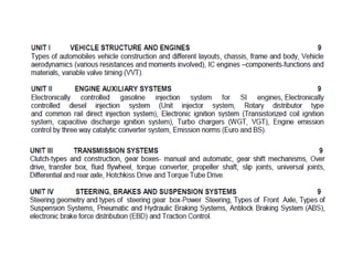
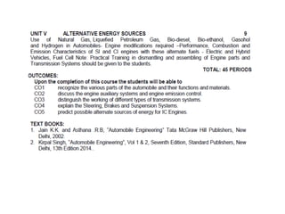
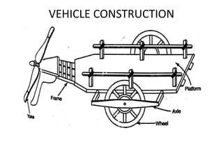
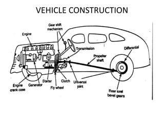
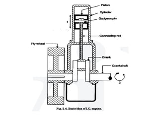
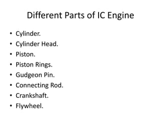
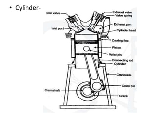
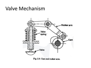
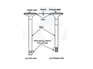
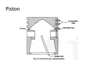
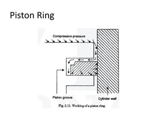
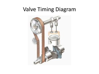
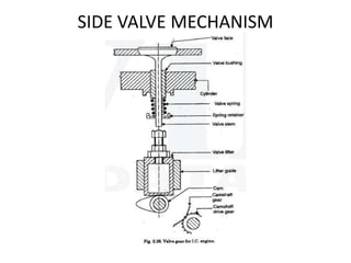
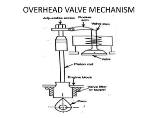
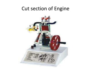
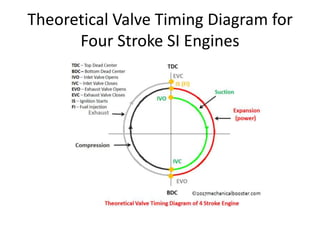
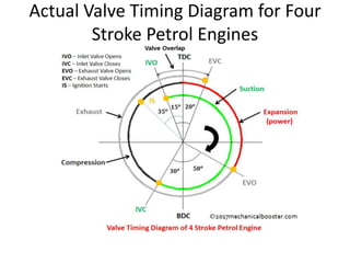
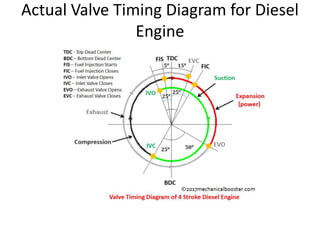
AUTOMOBILE ENGINEERING
ME8091
UNIT-I
VEHICLE STRUCTURE AND ENGINES
TYPES OF AUTOMOBILES
VEHICLE CONSTRUCTION
Different Parts of IC Engine
• Cylinder.
• Cylinder Head.
• Piston.
• Piston Rings.
• Gudgeon Pin.
• Connecting Rod.
• Crankshaft.
• Flywheel.
Different Parts of IC Engine
• Parts only Petrol Engine has-
• Spark Plug.
• Carburettor.
• Fuel Pump.
Parts only Diesel Engine has
• Fuel Pump.
• Fuel Injector
• Cylinder-
CYLINDER
• Cylinder contains gas under pressure and
guides the piston.
• The ideal form of a Plain Cylindrical Barrel in
which the piston slides.
• The Cylinder is made of hard grade cast iron
and usually made up of cast in one piece.
• Cylinder Head-
Cylinder Head
• One End of the Cylinder head is closed by
means of a removable cylinder head.
• Which usually contains the inlet or admission
valve for admitting the mixture of air and fuel,
also the exhaust valve which scavenges the
exhaust gas.
Valve Mechanism
Piston
Piston Ring
PISTON RING
• To provide a good sealing fit between the
piston and cylinder, piston is equipped with
piston rings.
• The rings are usually made of cast iron of fine
grains and high elasticity which will not
affected by the working heat. Some rings are
made of alloy Spring steel.
PISTON RINGS
Gudgeon Pin or Piston ring
Gudgeon pin
• They are made up of Hardened steel parallel
spindle fitted through the piston bosses and
the Small end bushes or eyes to allow the
connecting rods to swivel.
• Gudgeon pins are a press fit in the piston
bosses of light alloy piston when cold
Crankshafts
• Crank shaft of an IC Engine receives via its
cranks the efforts supplied by the pistons to
the connecting rods.
• It is usually made up of steel forging. But some
makers use special type of Cast iron such as
Spheroidal Graphite or Nickel Alloy Casting
which are Cheaper to produce and have good
service.
Crankshaft
Flywheel
• A flywheel (Steel or Cast iron Disc) secured on
the crank shaft performs the following
function-
• Bring the mechanism out of dead centres.
• Stores energy required to rotate the shaft
during preparatory strokes.
• Makes crankshaft rotation more uniform.
Flywheel
Chassis
• To construct any automobile, Chassis is the
basic requirement.
• Chassis is the backbone of the vehicle.
• It is the mounting of all the components
including the body. It is also called as carrying
unit.
LAYOUT OF CHASSIS
CLASSIFICATION OF CHASSIS
According to the fitting of engine
Main component of Chassis
• Frame.
• Front suspension.
• Steering Mechanism.
• Engine, Clutch and Gear Box.
• Radiator.
• Wheels.
• Propeller Shaft.
• Differential Units
Main Component of Chassis
• Clutch.
• Gear Box.
• Front Axle.
• Rear Axle
FRAME
• The Frame is the foundation for carrying the
Engine and body of the Vehicle.
• It is also carries steering, power trains.
• When the Engine, Wheels, Power trains,
Brackets and Steering system are fitted on the
frame, the assembly is known as Chassis.
FRAME CONSTRUCTION
Materials for Frame
 Mild steel sheet, Carbon steel sheet and
Nickel alloy steel sheet
The composition of Nickel alloy steel sheet
• Carbon - 0.25 to 0.35%
• Manganese – 0.35 to 0.75%
• Silicon – 0.30% (maximum)
• Nickel – 3%
• Phosphorus – 0.05% (max)
• Sulphur – 0.5% (max)
TYPES OF FRAME
1. CONVENTIONAL FRAME CONSTRUCTION
2. SEMI-INTEGRAL FRAME CONSTRUCTION
3. INTEGRAL OR FRAMELESS CONSTRUCTION
Conventional Frame
• It is also Known as Non-Load Carrying Frame,
here the load on the Vehicles are transferred
to the Suspension.
• These type of Frame is not suited for resist
torsion
• It mostly uses Channel Section, Tubular
Section and Box Section.
Integral Frame or frameless
• This frame is used now a days in most of the
cars, there is no frame and all the assembly
units are attached to the body.
• In this construction there is no frame and all
assembly units are attached to the body.
• They are assemble by using large number of
mild steel pressing
FRAMELESS CONSTRUCTION
Semi Integral Frame
• In some Vehicle half Frame is fixed in the
front end on which engine gear box and front
suspension is mounted.
• This types of frame load will be transferred to
the body.
• The frame however is heavy.
Semi Integral Frame
Loads on chassis frame
1. Loads of short duration
2. Combined loads of momentary duration
3. Inertia loads
4. Impact loads
5. Load due to road camber
6. Load due to wheel impact
7. Static loads
8. overloads
DEFECTS IN FRAME
1. Misalignment in horizontal and vertical plane
2. Twisting of main frame and sub-frames
3. Buckled main frame and sub-frames
4. Bent side members and dumb iron
5. Broken or loose gusset plates and rivets
Automobile Body
• Body is the super structure for all vehicles. It
may either be constructed separately and
bolted or manufactured integral with chassis.
• A body consist of windows, Doors, Engine
Cover, roof, Luggage cover etc.,
• The 60 to 70 % of the vehicle weight is
contributed by the Body.
Type of Body
• Car.
• Straight truck.
• Truck-Half Body.
• Truck-Platform.
• Tractor.
• Tractor with articulator trailer.
• Tanker.
• Dumper Truck.
Types of body
COMPONENTS OF CAR BODY
Body construction and its components
a). Structure: All load carrying elements are
defined as structure.
b). Finish: This group includes all unstressed
units such as bonnet, boot, lid, bumper etc.
c). Equipment: This group includes various parts
such as rim, seats, doors, window etc.
Floor assembly of a car
Materials for Body Construction
• The Material used for Construction parts of
the body are-
• Wood, Plastics, Toughened glass and
Aluminum.
• Wooden bodies requires a separate sheet
chassis frame to carry the load. It has low life
span and initial cost is high.
Working of four stroke petrol Engine
Working of four stroke Diesel Engine
Working of Four stroke Engine
Various stroke in IC Engine-
1. Suction or Induction Stroke.
2. Compression stroke.
3. Power Stroke or Expansion stroke.
4. Exhaust Stroke.
Working of Two Stroke Engine
Vehicle Aerodynamics
• Automotive Aerodynamics is the study of the
aerodynamics of road Vehicles.
• Its main goals are reducing drag and wind
noise, Minimizing noise emission and
preventing undesired lift force other cause of
aerodynamics Instability at high speeds.
• It is important to produce downforce to
improve traction and thus cornering abilities.
Types of resistance caused to vehicle
• Broadly the resistance can be categorized into
following categories-
1. Air Resistance.
2. Gradient Resistance.
3. Rolling Resistance.
4. Inertia Force.
RESISTANCES TO VEHICLE MOTION
1. Air resistance:
a. Size of vehicle b. Shape
c. Speed d. Wind velocity
2.Gradient resistances:
The component of the vehicle’s weight which is
parallel to the plane of the road. This component
remains constant but independent of the vehicle
speed.
3. Miscellaneous resistance:
a. Road characteristics b. Tyre characteristics
c. Vehicle weight d. Vehicle speed
AERODYNAMICS OF AUTOMOBILE
BODY
i) Drag force(Fx)
ii) Lift force(Fz)
iii) Cross wind force(Fy)
Drag force(Fx)
FX = CX ρv2A/2
Where
CX= drag coefficient
ρ= density of air
V= velocity of air
A = projected area of the vehicle viewed
from front
Lift force(Fz)
Fz = Cz ρv2A/2
Where
Cz= lift coefficient
ρ= density of air
V= velocity of air
A = projected area of the vehicle viewed
from front
Cross wind force(Fy)
• Pitching moment(MY): Is caused by the drag
force or lift force about y axis. This moment
makes the rear wheels lift off from the ground
and further it reduces the available traction.
• Yawing moment(Mz): Is caused by the cross
wind force (Fy) about Z.
• Rolling moment(My): is caused by the cross
wind force (Fy) about Z.
Valve Timing Diagram
SIDE VALVE MECHANISM
OVERHEAD VALVE MECHANISM
Cut section of Engine
Theoretical Valve Timing Diagram for
Four Stroke SI Engines
Actual Valve Timing Diagram for Four
Stroke Petrol Engines
Actual Valve Timing Diagram for Diesel
Engine
Variable Valve Timing Diagram
• The variable valve timing system alter the
valve timing suits engine speed and load
conditions. Although system condition.
• A petrol Engine has to operate at varying
engine speeds from idle, typically 750rpm,
through the high speed up to 7500 rpm and
above.
Variable valve timing
• Variable valve timing optimizes the over lap
caused by the varying speed.
• VVT enable good torque to be achieved over
the whole engine speed range but the added
benefit of valve overlap is to facilitate the
mixing of some exhaust gas with the fresh
charge of air.
Variable Valve Timing (VVT) for Four
Cylinder Engine
i). Slow engine speeds
ii). High engine speeds
iii). Valve opening period
Variable valve timing
• Slow Engine-
If the Inlet Valve timing is to altered so that
it is retarded or opened late all of the exhaust
gases so the cylinder will be filled with fresh and
uncontaminated mixture.
Variable Valve Timing
• High Engine Speed-
At the high Engine speed, The fresh
mixture can be drawn into cylinder by the
depression caused by the flow of exhaust gas
through the exhaust valve.
Variable Valve Timing
• Valve Opening Period-
Engine in low speed, the valve opening
period allows fresh charge.
Engine high Speed, the Valve Lift timing is
Increased, as a result there is increase in the
engine power.
Types of variable valve timing
1. Cam changing VVT
2. Cam phasing VVT
3. Combined cam changing and cam phasing
VVT
Cam Changing
• This type of VVT uses various cam profiles to
lift valves based on load and speed. It is also
uses two rockers arms for normal working in
its two intake valves and third rocker arms is
placed between other two arms.
• If the Engine rises speed of 6000rpm, the ECU
will activate and lock the center rocker arm
and open the valve for long duration.
Cam Phasing VVT
• It is obtained by just shifting the cam phase
angle, at the high speed, the inlet chamber
rotates 30 degrees advances to enable
previous intake.
• It is achieved by the engine management
system based on the need and type of
actuation.
Advantages of VVT
• It allows the recirculate internal Exhaust gas.
• Increased torque can be obtained.
• It ensures better fuel economy.
• It reduces nitrogen oxides.
• Hydrocarbon emissions can be controlled.

Vehicle Structure and Engines

  • 1.
  • 4.
  • 8.
  • 9.
  • 10.
  • 12.
    Different Parts ofIC Engine • Cylinder. • Cylinder Head. • Piston. • Piston Rings. • Gudgeon Pin. • Connecting Rod. • Crankshaft. • Flywheel.
  • 13.
    Different Parts ofIC Engine • Parts only Petrol Engine has- • Spark Plug. • Carburettor. • Fuel Pump. Parts only Diesel Engine has • Fuel Pump. • Fuel Injector
  • 14.
  • 15.
    CYLINDER • Cylinder containsgas under pressure and guides the piston. • The ideal form of a Plain Cylindrical Barrel in which the piston slides. • The Cylinder is made of hard grade cast iron and usually made up of cast in one piece.
  • 16.
  • 17.
    Cylinder Head • OneEnd of the Cylinder head is closed by means of a removable cylinder head. • Which usually contains the inlet or admission valve for admitting the mixture of air and fuel, also the exhaust valve which scavenges the exhaust gas.
  • 18.
  • 20.
  • 21.
  • 22.
    PISTON RING • Toprovide a good sealing fit between the piston and cylinder, piston is equipped with piston rings. • The rings are usually made of cast iron of fine grains and high elasticity which will not affected by the working heat. Some rings are made of alloy Spring steel.
  • 23.
  • 24.
    Gudgeon Pin orPiston ring
  • 25.
    Gudgeon pin • Theyare made up of Hardened steel parallel spindle fitted through the piston bosses and the Small end bushes or eyes to allow the connecting rods to swivel. • Gudgeon pins are a press fit in the piston bosses of light alloy piston when cold
  • 26.
    Crankshafts • Crank shaftof an IC Engine receives via its cranks the efforts supplied by the pistons to the connecting rods. • It is usually made up of steel forging. But some makers use special type of Cast iron such as Spheroidal Graphite or Nickel Alloy Casting which are Cheaper to produce and have good service.
  • 27.
  • 28.
    Flywheel • A flywheel(Steel or Cast iron Disc) secured on the crank shaft performs the following function- • Bring the mechanism out of dead centres. • Stores energy required to rotate the shaft during preparatory strokes. • Makes crankshaft rotation more uniform.
  • 29.
  • 30.
    Chassis • To constructany automobile, Chassis is the basic requirement. • Chassis is the backbone of the vehicle. • It is the mounting of all the components including the body. It is also called as carrying unit.
  • 31.
  • 32.
    CLASSIFICATION OF CHASSIS Accordingto the fitting of engine
  • 34.
    Main component ofChassis • Frame. • Front suspension. • Steering Mechanism. • Engine, Clutch and Gear Box. • Radiator. • Wheels. • Propeller Shaft. • Differential Units
  • 35.
    Main Component ofChassis • Clutch. • Gear Box. • Front Axle. • Rear Axle
  • 36.
    FRAME • The Frameis the foundation for carrying the Engine and body of the Vehicle. • It is also carries steering, power trains. • When the Engine, Wheels, Power trains, Brackets and Steering system are fitted on the frame, the assembly is known as Chassis.
  • 37.
  • 38.
    Materials for Frame Mild steel sheet, Carbon steel sheet and Nickel alloy steel sheet The composition of Nickel alloy steel sheet • Carbon - 0.25 to 0.35% • Manganese – 0.35 to 0.75% • Silicon – 0.30% (maximum) • Nickel – 3% • Phosphorus – 0.05% (max) • Sulphur – 0.5% (max)
  • 39.
    TYPES OF FRAME 1.CONVENTIONAL FRAME CONSTRUCTION 2. SEMI-INTEGRAL FRAME CONSTRUCTION 3. INTEGRAL OR FRAMELESS CONSTRUCTION
  • 40.
    Conventional Frame • Itis also Known as Non-Load Carrying Frame, here the load on the Vehicles are transferred to the Suspension. • These type of Frame is not suited for resist torsion • It mostly uses Channel Section, Tubular Section and Box Section.
  • 42.
    Integral Frame orframeless • This frame is used now a days in most of the cars, there is no frame and all the assembly units are attached to the body. • In this construction there is no frame and all assembly units are attached to the body. • They are assemble by using large number of mild steel pressing
  • 43.
  • 44.
    Semi Integral Frame •In some Vehicle half Frame is fixed in the front end on which engine gear box and front suspension is mounted. • This types of frame load will be transferred to the body. • The frame however is heavy.
  • 45.
  • 46.
    Loads on chassisframe 1. Loads of short duration 2. Combined loads of momentary duration 3. Inertia loads 4. Impact loads 5. Load due to road camber 6. Load due to wheel impact 7. Static loads 8. overloads
  • 47.
    DEFECTS IN FRAME 1.Misalignment in horizontal and vertical plane 2. Twisting of main frame and sub-frames 3. Buckled main frame and sub-frames 4. Bent side members and dumb iron 5. Broken or loose gusset plates and rivets
  • 48.
    Automobile Body • Bodyis the super structure for all vehicles. It may either be constructed separately and bolted or manufactured integral with chassis. • A body consist of windows, Doors, Engine Cover, roof, Luggage cover etc., • The 60 to 70 % of the vehicle weight is contributed by the Body.
  • 49.
    Type of Body •Car. • Straight truck. • Truck-Half Body. • Truck-Platform. • Tractor. • Tractor with articulator trailer. • Tanker. • Dumper Truck.
  • 50.
  • 51.
  • 52.
    Body construction andits components a). Structure: All load carrying elements are defined as structure. b). Finish: This group includes all unstressed units such as bonnet, boot, lid, bumper etc. c). Equipment: This group includes various parts such as rim, seats, doors, window etc.
  • 53.
  • 54.
    Materials for BodyConstruction • The Material used for Construction parts of the body are- • Wood, Plastics, Toughened glass and Aluminum. • Wooden bodies requires a separate sheet chassis frame to carry the load. It has low life span and initial cost is high.
  • 55.
    Working of fourstroke petrol Engine
  • 56.
    Working of fourstroke Diesel Engine
  • 57.
    Working of Fourstroke Engine Various stroke in IC Engine- 1. Suction or Induction Stroke. 2. Compression stroke. 3. Power Stroke or Expansion stroke. 4. Exhaust Stroke.
  • 58.
    Working of TwoStroke Engine
  • 59.
    Vehicle Aerodynamics • AutomotiveAerodynamics is the study of the aerodynamics of road Vehicles. • Its main goals are reducing drag and wind noise, Minimizing noise emission and preventing undesired lift force other cause of aerodynamics Instability at high speeds. • It is important to produce downforce to improve traction and thus cornering abilities.
  • 60.
    Types of resistancecaused to vehicle • Broadly the resistance can be categorized into following categories- 1. Air Resistance. 2. Gradient Resistance. 3. Rolling Resistance. 4. Inertia Force.
  • 61.
    RESISTANCES TO VEHICLEMOTION 1. Air resistance: a. Size of vehicle b. Shape c. Speed d. Wind velocity 2.Gradient resistances: The component of the vehicle’s weight which is parallel to the plane of the road. This component remains constant but independent of the vehicle speed. 3. Miscellaneous resistance: a. Road characteristics b. Tyre characteristics c. Vehicle weight d. Vehicle speed
  • 62.
    AERODYNAMICS OF AUTOMOBILE BODY i)Drag force(Fx) ii) Lift force(Fz) iii) Cross wind force(Fy)
  • 63.
    Drag force(Fx) FX =CX ρv2A/2 Where CX= drag coefficient ρ= density of air V= velocity of air A = projected area of the vehicle viewed from front
  • 64.
    Lift force(Fz) Fz =Cz ρv2A/2 Where Cz= lift coefficient ρ= density of air V= velocity of air A = projected area of the vehicle viewed from front
  • 65.
    Cross wind force(Fy) •Pitching moment(MY): Is caused by the drag force or lift force about y axis. This moment makes the rear wheels lift off from the ground and further it reduces the available traction. • Yawing moment(Mz): Is caused by the cross wind force (Fy) about Z. • Rolling moment(My): is caused by the cross wind force (Fy) about Z.
  • 66.
  • 67.
  • 68.
  • 69.
  • 70.
    Theoretical Valve TimingDiagram for Four Stroke SI Engines
  • 71.
    Actual Valve TimingDiagram for Four Stroke Petrol Engines
  • 72.
    Actual Valve TimingDiagram for Diesel Engine
  • 73.
    Variable Valve TimingDiagram • The variable valve timing system alter the valve timing suits engine speed and load conditions. Although system condition. • A petrol Engine has to operate at varying engine speeds from idle, typically 750rpm, through the high speed up to 7500 rpm and above.
  • 74.
    Variable valve timing •Variable valve timing optimizes the over lap caused by the varying speed. • VVT enable good torque to be achieved over the whole engine speed range but the added benefit of valve overlap is to facilitate the mixing of some exhaust gas with the fresh charge of air.
  • 76.
    Variable Valve Timing(VVT) for Four Cylinder Engine i). Slow engine speeds ii). High engine speeds iii). Valve opening period
  • 77.
    Variable valve timing •Slow Engine- If the Inlet Valve timing is to altered so that it is retarded or opened late all of the exhaust gases so the cylinder will be filled with fresh and uncontaminated mixture.
  • 78.
    Variable Valve Timing •High Engine Speed- At the high Engine speed, The fresh mixture can be drawn into cylinder by the depression caused by the flow of exhaust gas through the exhaust valve.
  • 79.
    Variable Valve Timing •Valve Opening Period- Engine in low speed, the valve opening period allows fresh charge. Engine high Speed, the Valve Lift timing is Increased, as a result there is increase in the engine power.
  • 80.
    Types of variablevalve timing 1. Cam changing VVT 2. Cam phasing VVT 3. Combined cam changing and cam phasing VVT
  • 81.
    Cam Changing • Thistype of VVT uses various cam profiles to lift valves based on load and speed. It is also uses two rockers arms for normal working in its two intake valves and third rocker arms is placed between other two arms. • If the Engine rises speed of 6000rpm, the ECU will activate and lock the center rocker arm and open the valve for long duration.
  • 82.
    Cam Phasing VVT •It is obtained by just shifting the cam phase angle, at the high speed, the inlet chamber rotates 30 degrees advances to enable previous intake. • It is achieved by the engine management system based on the need and type of actuation.
  • 83.
    Advantages of VVT •It allows the recirculate internal Exhaust gas. • Increased torque can be obtained. • It ensures better fuel economy. • It reduces nitrogen oxides. • Hydrocarbon emissions can be controlled.