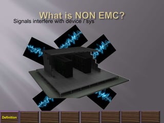
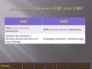
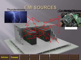
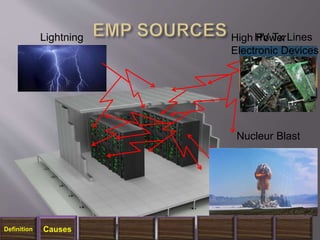
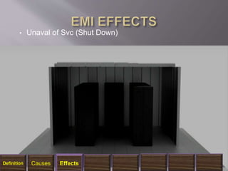
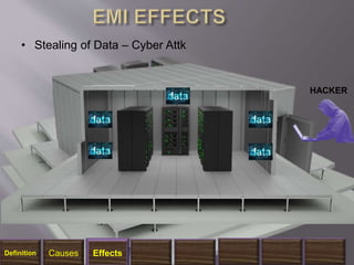
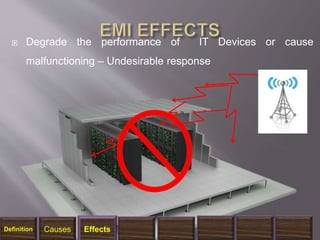
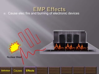
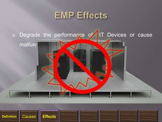
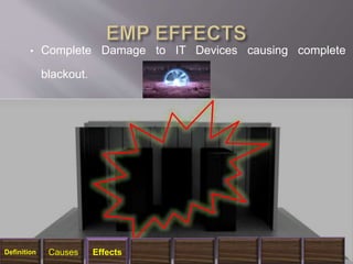
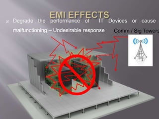
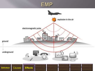
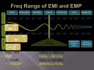
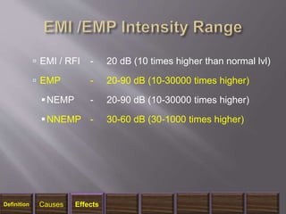
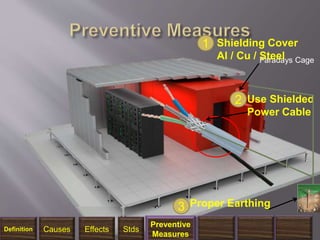
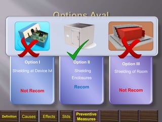
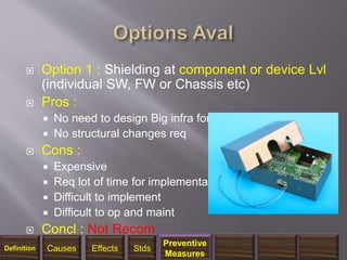
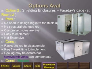
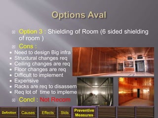
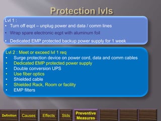
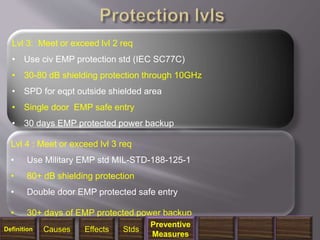
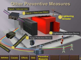
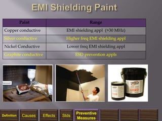
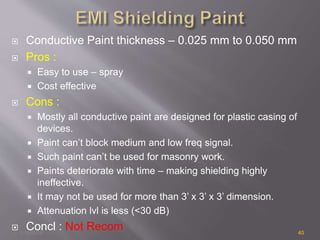
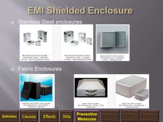
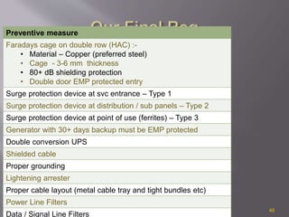
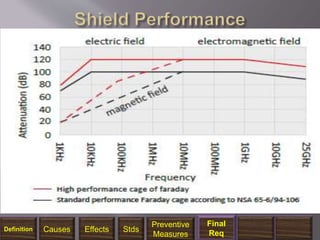
1/14/2018 2
● Part – I What is EMI, EMP and EMC?
● Part – II Causes / sources of EMI and EMP
● Part – III Effects of EMI and EMP
● Part – IV Mil Stds for EMI / EMP Protection of C4I Facilities
● Part – V Preventive Measures
1/14/2018 3
What is EMI, EMP and EMC?
Definition
Unwanted Signal and Interference
Definition
 Electromagnetic Pulse - Powerful pulse of short duration
and high intensity electromagnetic radiation such as
lightening or nuclear explosion.
Nuclear Blast
Definition
• Ability of IT Eqpt to operate in proximity of
electromagnetic envmt (EMI&EMP), without causing
or suffering unacceptable degradation in output or
performance
Definition
• 100% electronic shielding and containment.
• No EMI signal can enter inside DC
Definition
No Signals can go outside
Definition
Signals interfere with device / sys
Definition
EMI EMP
EMI is a low intensity
interference
EMP is a high intensity interference
Interfere the electronic /
electrical devices but does not
cause damage
It damages electrical / electronic eqpt
Definition
1/14/2018 11
Causes / Sources of EMI and EMP?
Definition Causes
Comm / Sig TowersTx LinesMobile PhonesElectronic DevicesThunderstroms
Definition Causes
HV Tx LinesHigh Power
Electronic Devices
Lightning
Nucleur Blast
Definition Causes
1/14/2018 14
Effects of EMI and EMP?
Definition Causes Effects
• Unaval of Svc (Shut Down)
Definition Causes Effects
HACKER
• Stealing of Data – Cyber Attk
Definition Causes Effects
 Degrade the performance of IT Devices or cause
malfunctioning – Undesirable response
Definition Causes Effects
 Cause elec fire and burning of electronic devices
Nuclear Blast
Definition Causes Effects
 Degrade the performance of IT Devices or cause
malfunctioning – Undesirable response
Definition Causes Effects
• Complete Damage to IT Devices causing complete
blackout.
Definition Causes Effects
 Degrade the performance of IT Devices or cause
malfunctioning – Undesirable response Comm / Sig Towers
1/14/2018 22
Definition Causes Effects
103 1010
EMI
104 1011
RFI
103 108
EMP
1010
• EMI / RFI - 10KHz to 300GHz
• EMP - 3 KHz – 300 GHz
• NEMP - 1KHz to 100 MHz
• NNEMP - 200MHz to 5GHz
 EMI / RFI - 20 dB (10 times higher than normal lvl)
 EMP - 20-90 dB (10-30000 times higher)
NEMP - 20-90 dB (10-30000 times higher)
NNEMP - 30-60 dB (30-1000 times higher)
Definition Causes Effects
 EMI - 20 dB
 RFI - 20 dB
 EMP - 20-90 dB
 NEMP - 20-40 dB or 60-90 dB
 NNEMP - 30-60 dB
 HEMP - 20-40 dB
1/14/2018 26
Definition Causes Effects
1/14/2018 27
Mil Stds For EMI / EMP Protection of C4I
Facility
Definition Causes Effects Stds
 MIL-STD-188-125-1 Fixed C4I Facilities
 MIL-STD-188-125-2 Transportable C4I Facilities
 MIL-STD-461 Test equipment for electromagnetic
compatibility
1/14/2018 28
Definition Causes Effects Stds
 Standard for EMP hardening of fixed ground-based
and transportable C4I facilities and prescribed fol:-
 Min performance Req
 Min test req
 Design and test criteria
1/14/2018 29
Definition Causes Effects Stds
1/14/2018 30
Preventive Measures – EMI / EMP
Definition Causes Effects Stds
Preventive
Measures
1/14/2018 31
Faradays Cage
Shielding Cover
Al / Cu / Steel
1
Use Shielded
Power Cable
2
Proper Earthing3
Definition Causes Effects Stds
Preventive
Measures
1/14/2018 32
Option I
Shielding at Device lvl
Not Recom
Option II
Shielding
Enclosures
Recom
Option III
Shielding of Room
Not Recom
Definition Causes Effects Stds
Preventive
Measures
 Option 1 : Shielding at component or device Lvl
(individual SW, FW or Chassis etc)
 Pros :
 No need to design Big infra for shielding
 No structural changes req
 Cons :
 Expensive
 Req lot of time for implementation
 Difficult to implement
 Difficult to op and maint
 Concl : Not Recom
1/14/2018 33
Definition Causes Effects Stds
Preventive
Measures
 Option 2 : Shielding Enclosures – Faraday’s cage (at
Row Lvl )
 Pros :
 No need to design Big infra for shielding
 No structural changes req
 Customized solns are aval
 Easy to implement
 Not Expensive
 Cons :
 Racks are req to disassemble
 Req 1 week time to implement
 Cooling may be disturb but
honeycomb vents can compensate
 Concl : Recom
1/14/2018 34
Definition Causes Effects Stds
Preventive
Measures
 Option 3 : Shielding of Room (6 sided shielding
of room )
 Cons :
 Need to design Big infra for shielding
 Structural changes req
 Ceiling changes are req
 Floor changes are req
 Difficult to implement
 Expensive
 Racks are req to disassemble
 Req lot of time to implement
 Concl : Not Recom
1/14/2018 35
Definition Causes Effects Stds
Preventive
Measures
1/14/2018 36
Lvl 2 : Meet or exceed lvl 1 req
• Surge protection device on power cord, data and comm cables
• Dedicated EMP protected power supply
• Double conversion UPS
• Use fiber optics
• Shielded cable
• Shielded Rack, Room or facility
• EMP filters
•
Lvl 1 :
• Turn off eqpt – unplug power and data / comm lines
• Wrap spare electronic eqpt with aluminum foil
• Dedicated EMP protected backup power supply for 1 week
Definition Causes Effects Stds
Preventive
Measures
1/14/2018 37
Lvl 4 : Meet or exceed lvl 3 req
• Use Military EMP std MIL-STD-188-125-1
• 80+ dB shielding protection
• Double door EMP protected safe entry
• 30+ days of EMP protected power backup
Lvl 3: Meet or exceed lvl 2 req
• Use civ EMP protection std (IEC SC77C)
• 30-80 dB shielding protection through 10GHz
• SPD for eqpt outside shielded area
• Single door EMP safe entry
• 30 days EMP protected power backup
Definition Causes Effects Stds
Preventive
Measures
1/14/2018 38
Signal / telecom Line
Lightening
Arrester
5
2
Surge Protection Device3
Lightening Protection Device4
Definition Causes Effects Stds
Preventive
Measures
1/14/2018 39
Paint Range
Copper conductive EMI shielding appl (>30 MHz)
Silver conductive Higher freq EMI shielding appl
Nickel Conductive Lower freq EMI shielding appl
Graphite conductive ESD prevention appls
Definition Causes Effects Stds
Preventive
Measures
 Conductive Paint thickness – 0.025 mm to 0.050 mm
 Pros :
 Easy to use – spray
 Cost effective
 Cons :
 Mostly all conductive paint are designed for plastic casing of
devices.
 Paint can’t block medium and low freq signal.
 Such paint can’t be used for masonry work.
 Paints deteriorate with time – making shielding highly
ineffective.
 It may not be used for more than 3’ x 3’ x 3’ dimension.
 Attenuation lvl is less (<30 dB)
 Concl : Not Recom1/14/2018 40
 EMI Shielding Gaskets – use to avoid gaps and
completely contain the shielding
1/14/2018 41
Definition Causes Effects Stds
Preventive
Measures
 Stainless Steel enclosures
 Fabric Enclosures
1/14/2018 42
Definition Causes Effects Stds
Preventive
Measures
 EMI Shielding Fabric - 35 to 45 dB Protection
with double layer made of strong and
conductive textile
 Ni/Cu/Co Fabric Tape
1/14/2018 43
Definition Causes Effects Stds
Preventive
Measures
1/14/2018 44
Final Req
Definition Causes Effects Stds
Preventive
Measures
Final
Req
1/14/2018 45
Preventive measure
Faradays cage on double row (HAC) :-
• Material – Copper (preferred steel)
• Cage - 3-6 mm thickness
• 80+ dB shielding protection
• Double door EMP protected entry
Surge protection device at svc entrance – Type 1
Surge protection device at distribution / sub panels – Type 2
Surge protection device at point of use (ferrites) – Type 3
Generator with 30+ days backup must be EMP protected
Double conversion UPS
Shielded cable
Proper grounding
Lightening arrester
Proper cable layout (metal cable tray and tight bundles etc)
Power Line Filters
Data / Signal Line Filters
Definition Causes Effects Stds
Preventive
Measures
Final
Req
1/14/2018 48

EMI and EMP Protection and Shielding

  • 2.
    1/14/2018 2 ● Part– I What is EMI, EMP and EMC? ● Part – II Causes / sources of EMI and EMP ● Part – III Effects of EMI and EMP ● Part – IV Mil Stds for EMI / EMP Protection of C4I Facilities ● Part – V Preventive Measures
  • 3.
    1/14/2018 3 What isEMI, EMP and EMC? Definition
  • 4.
    Unwanted Signal andInterference Definition
  • 5.
     Electromagnetic Pulse- Powerful pulse of short duration and high intensity electromagnetic radiation such as lightening or nuclear explosion. Nuclear Blast Definition
  • 6.
    • Ability ofIT Eqpt to operate in proximity of electromagnetic envmt (EMI&EMP), without causing or suffering unacceptable degradation in output or performance Definition
  • 7.
    • 100% electronicshielding and containment. • No EMI signal can enter inside DC Definition
  • 8.
    No Signals cango outside Definition
  • 9.
    Signals interfere withdevice / sys Definition
  • 10.
    EMI EMP EMI isa low intensity interference EMP is a high intensity interference Interfere the electronic / electrical devices but does not cause damage It damages electrical / electronic eqpt Definition
  • 11.
    1/14/2018 11 Causes /Sources of EMI and EMP? Definition Causes
  • 12.
    Comm / SigTowersTx LinesMobile PhonesElectronic DevicesThunderstroms Definition Causes
  • 13.
    HV Tx LinesHighPower Electronic Devices Lightning Nucleur Blast Definition Causes
  • 14.
    1/14/2018 14 Effects ofEMI and EMP? Definition Causes Effects
  • 15.
    • Unaval ofSvc (Shut Down) Definition Causes Effects
  • 16.
    HACKER • Stealing ofData – Cyber Attk Definition Causes Effects
  • 17.
     Degrade theperformance of IT Devices or cause malfunctioning – Undesirable response Definition Causes Effects
  • 18.
     Cause elecfire and burning of electronic devices Nuclear Blast Definition Causes Effects
  • 19.
     Degrade theperformance of IT Devices or cause malfunctioning – Undesirable response Definition Causes Effects
  • 20.
    • Complete Damageto IT Devices causing complete blackout. Definition Causes Effects
  • 21.
     Degrade theperformance of IT Devices or cause malfunctioning – Undesirable response Comm / Sig Towers
  • 22.
  • 23.
    103 1010 EMI 104 1011 RFI 103108 EMP 1010 • EMI / RFI - 10KHz to 300GHz • EMP - 3 KHz – 300 GHz • NEMP - 1KHz to 100 MHz • NNEMP - 200MHz to 5GHz
  • 24.
     EMI /RFI - 20 dB (10 times higher than normal lvl)  EMP - 20-90 dB (10-30000 times higher) NEMP - 20-90 dB (10-30000 times higher) NNEMP - 30-60 dB (30-1000 times higher) Definition Causes Effects
  • 25.
     EMI -20 dB  RFI - 20 dB  EMP - 20-90 dB  NEMP - 20-40 dB or 60-90 dB  NNEMP - 30-60 dB  HEMP - 20-40 dB
  • 26.
  • 27.
    1/14/2018 27 Mil StdsFor EMI / EMP Protection of C4I Facility Definition Causes Effects Stds
  • 28.
     MIL-STD-188-125-1 FixedC4I Facilities  MIL-STD-188-125-2 Transportable C4I Facilities  MIL-STD-461 Test equipment for electromagnetic compatibility 1/14/2018 28 Definition Causes Effects Stds
  • 29.
     Standard forEMP hardening of fixed ground-based and transportable C4I facilities and prescribed fol:-  Min performance Req  Min test req  Design and test criteria 1/14/2018 29 Definition Causes Effects Stds
  • 30.
    1/14/2018 30 Preventive Measures– EMI / EMP Definition Causes Effects Stds Preventive Measures
  • 31.
    1/14/2018 31 Faradays Cage ShieldingCover Al / Cu / Steel 1 Use Shielded Power Cable 2 Proper Earthing3 Definition Causes Effects Stds Preventive Measures
  • 32.
    1/14/2018 32 Option I Shieldingat Device lvl Not Recom Option II Shielding Enclosures Recom Option III Shielding of Room Not Recom Definition Causes Effects Stds Preventive Measures
  • 33.
     Option 1: Shielding at component or device Lvl (individual SW, FW or Chassis etc)  Pros :  No need to design Big infra for shielding  No structural changes req  Cons :  Expensive  Req lot of time for implementation  Difficult to implement  Difficult to op and maint  Concl : Not Recom 1/14/2018 33 Definition Causes Effects Stds Preventive Measures
  • 34.
     Option 2: Shielding Enclosures – Faraday’s cage (at Row Lvl )  Pros :  No need to design Big infra for shielding  No structural changes req  Customized solns are aval  Easy to implement  Not Expensive  Cons :  Racks are req to disassemble  Req 1 week time to implement  Cooling may be disturb but honeycomb vents can compensate  Concl : Recom 1/14/2018 34 Definition Causes Effects Stds Preventive Measures
  • 35.
     Option 3: Shielding of Room (6 sided shielding of room )  Cons :  Need to design Big infra for shielding  Structural changes req  Ceiling changes are req  Floor changes are req  Difficult to implement  Expensive  Racks are req to disassemble  Req lot of time to implement  Concl : Not Recom 1/14/2018 35 Definition Causes Effects Stds Preventive Measures
  • 36.
    1/14/2018 36 Lvl 2: Meet or exceed lvl 1 req • Surge protection device on power cord, data and comm cables • Dedicated EMP protected power supply • Double conversion UPS • Use fiber optics • Shielded cable • Shielded Rack, Room or facility • EMP filters • Lvl 1 : • Turn off eqpt – unplug power and data / comm lines • Wrap spare electronic eqpt with aluminum foil • Dedicated EMP protected backup power supply for 1 week Definition Causes Effects Stds Preventive Measures
  • 37.
    1/14/2018 37 Lvl 4: Meet or exceed lvl 3 req • Use Military EMP std MIL-STD-188-125-1 • 80+ dB shielding protection • Double door EMP protected safe entry • 30+ days of EMP protected power backup Lvl 3: Meet or exceed lvl 2 req • Use civ EMP protection std (IEC SC77C) • 30-80 dB shielding protection through 10GHz • SPD for eqpt outside shielded area • Single door EMP safe entry • 30 days EMP protected power backup Definition Causes Effects Stds Preventive Measures
  • 38.
    1/14/2018 38 Signal /telecom Line Lightening Arrester 5 2 Surge Protection Device3 Lightening Protection Device4 Definition Causes Effects Stds Preventive Measures
  • 39.
    1/14/2018 39 Paint Range Copperconductive EMI shielding appl (>30 MHz) Silver conductive Higher freq EMI shielding appl Nickel Conductive Lower freq EMI shielding appl Graphite conductive ESD prevention appls Definition Causes Effects Stds Preventive Measures
  • 40.
     Conductive Paintthickness – 0.025 mm to 0.050 mm  Pros :  Easy to use – spray  Cost effective  Cons :  Mostly all conductive paint are designed for plastic casing of devices.  Paint can’t block medium and low freq signal.  Such paint can’t be used for masonry work.  Paints deteriorate with time – making shielding highly ineffective.  It may not be used for more than 3’ x 3’ x 3’ dimension.  Attenuation lvl is less (<30 dB)  Concl : Not Recom1/14/2018 40
  • 41.
     EMI ShieldingGaskets – use to avoid gaps and completely contain the shielding 1/14/2018 41 Definition Causes Effects Stds Preventive Measures
  • 42.
     Stainless Steelenclosures  Fabric Enclosures 1/14/2018 42 Definition Causes Effects Stds Preventive Measures
  • 43.
     EMI ShieldingFabric - 35 to 45 dB Protection with double layer made of strong and conductive textile  Ni/Cu/Co Fabric Tape 1/14/2018 43 Definition Causes Effects Stds Preventive Measures
  • 44.
    1/14/2018 44 Final Req DefinitionCauses Effects Stds Preventive Measures Final Req
  • 45.
    1/14/2018 45 Preventive measure Faradayscage on double row (HAC) :- • Material – Copper (preferred steel) • Cage - 3-6 mm thickness • 80+ dB shielding protection • Double door EMP protected entry Surge protection device at svc entrance – Type 1 Surge protection device at distribution / sub panels – Type 2 Surge protection device at point of use (ferrites) – Type 3 Generator with 30+ days backup must be EMP protected Double conversion UPS Shielded cable Proper grounding Lightening arrester Proper cable layout (metal cable tray and tight bundles etc) Power Line Filters Data / Signal Line Filters
  • 46.
    Definition Causes EffectsStds Preventive Measures Final Req
  • 48.

Editor's Notes

  • #25 Shielding b/w 60- 90 db is consiered high lvl and b/w 90- 120 db is exceptional
  • #26 Shielding b/w 60- 90 db is consiered high lvl and b/w 90- 120 db is exceptional