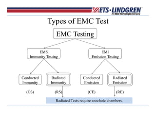
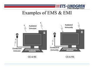
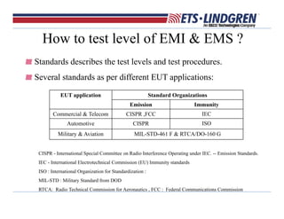
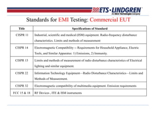
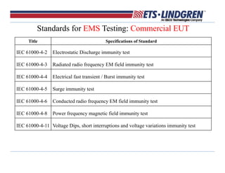
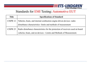
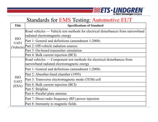
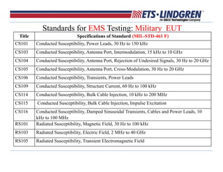
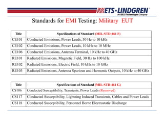
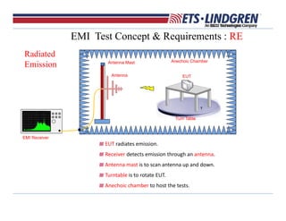
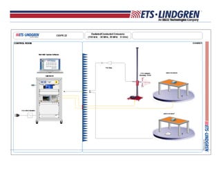
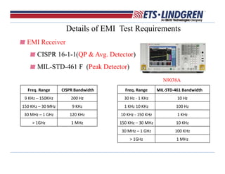
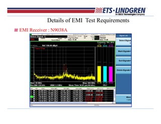
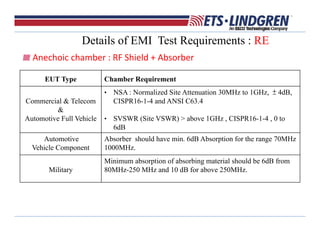
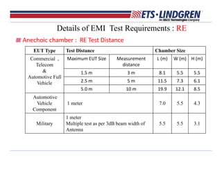
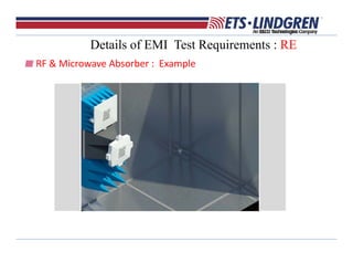
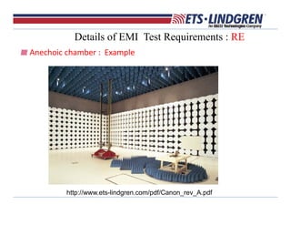
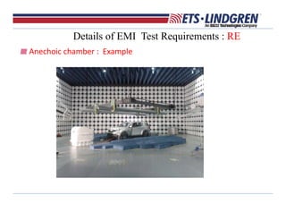
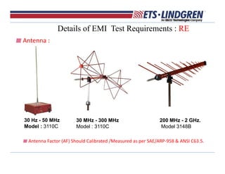
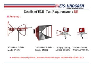
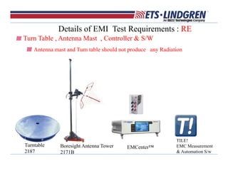
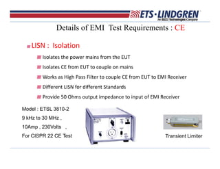
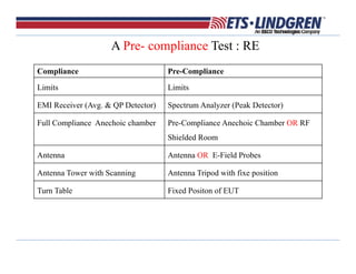
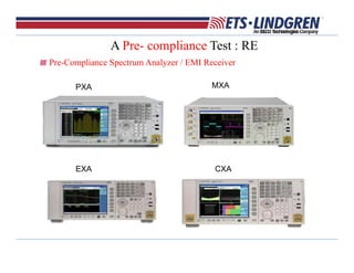
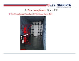
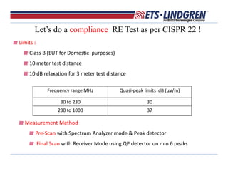
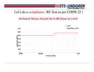
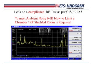
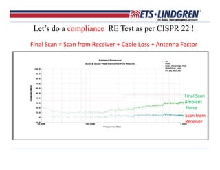
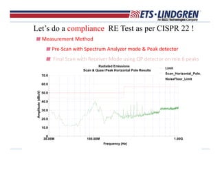
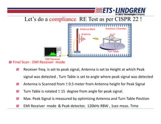
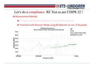
The Surest Solution, By Any MeasureThe Surest Solution, By Any Measure
Introduction to EMC
Pre-Compliance and Compliance Measurements :
Radiated and Conducted Emission
Introduction to EMC
Pre-Compliance and Compliance Measurements :
Radiated and Conducted Emission
Jitender Singh
RF Engineer
+91 9880 551177
jitender.singh@ets-lindgren.com
Jitender Singh
RF Engineer
+91 9880 551177
jitender.singh@ets-lindgren.com
Outline
Introduction to EMC Testing
Solutions For Conducted & Radiated Emission Test Systems
Pre-Compliance Solutions
Full Compliance Solutions
Summary
Introduction to EMC
EMC stands for ElectroMagnetic Compatibility
EMC can be separated into two categories
EMI The device should not emit unintentional EM energy
over regulated limits  Interference (emission)
EMS The device must maintain proper functionality under
potentially high level of EM radiation/emission in
circumstantial operational environment  Susceptibility
(immunity)
Introduction to EMC
EMC
EMIEMS I will kill you with
my emissions.
I am not afraid
of you. I have
good immunity.
Types of EMC Test
EMC Testing
EMI
Emission Testing
EMS
Immunity Testing
Conducted
Immunity
(CS)
Conducted
Emission
(CE)
Radiated
Emission
(RE)
Radiated
Immunity
(RS)
Radiated Tests require anechoic chambers.
Examples of EMS & EMI
CE & RE CS & RS
EMC Design Considerations
EM Interference/Emissions (EMI) are normally generated by:
– Internal processor digital clock(s).
– Power lines and/or interface cables/harnesses
– Openings and/or ventilation holes of the equipment case
– Signal line layouts and grounding in PCB
EM Susceptibility (EMS) are normally coming from
– External signal causing partial/total malfunctioning
– Power lines and/or interface cables/harnesses
– Openings and/or ventilation holes of the equipment case
– Signal line layouts and grounding in PCB
EMC designs adds about 1 to 5% of overall product cost.
Level of Emission & Immunity ?
Depends on the EUT application .
We can have EUT applications in three broad categories :
Commercial & Telecom
Automotive
Military & Aviation
EMC Testing is performed for component and full system.
How to test level of EMI & EMS ?
Standards describes the test levels and test procedures.
Several standards as per different EUT applications:
CISPR - International Special Committee on Radio Interference Operating under IEC. -- Emission Standards.
IEC - International Electrotechnical Commission (EU) Immunity standards
ISO : International Organization for Standardization :
MIL-STD : Military Standard from DOD
RTCA: Radio Technical Commission for Aeronautics , FCC : Federal Communications Commission
EUT application Standard Organizations
Emission Immunity
Commercial & Telecom CISPR ,FCC IEC
Automotive CISPR ISO
Military & Aviation MIL-STD-461 F & RTCA/DO-160 G
Standards for EMI Testing: Commercial EUT
Title Specifications of Standard
CISPR 11 Industrial, scientific and medical (ISM) equipment. Radio-frequency disturbance
characteristics. Limits and methods of measurement
CISPR 14 Electromagnetic Compatibility -- Requirements for Household Appliance, Electric
Tools, and Similar Apparatus: 1) Emissions, 2) Immunity.
CISPR 15 Limits and methods of measurement of radio disturbance characteristics of Electrical
lighting and similar equipment.
CISPR 22 Information Technology Equipment—Radio Disturbance Characteristics—Limits and
Methods of Measurement.
CISPR 32 Electromagnetic compatibility of multimedia equipment. Emission requirements
FCC 15 & 18 RF Devices , ITE & ISM instruments
Standards for EMS Testing: Commercial EUT
Title Specifications of Standard
IEC 61000-4-2 Electrostatic Discharge immunity test
IEC 61000-4-3 Radiated radio frequency EM field immunity test
IEC 61000-4-4 Electrical fast transient / Burst immunity test
IEC 61000-4-5 Surge immunity test
IEC 61000-4-6 Conducted radio frequency EM field immunity test
IEC 61000-4-8 Power frequency magnetic field immunity test
IEC 61000-4-11 Voltage Dips, short interruptions and voltage variations immunity test
Standards for EMI Testing: Automotive EUT
Title Specifications of Standard
CISPR 12 Vehicles, boats, and internal combustion engine driven devices -radio
disturbance characteristics -limits and methods of measurement
CISPR 25 Radio disturbance characteristics for the protection of receivers used on board
vehicles, boats, and on devices—Limits and Methods of Measurement.
Gain Variation
Title Specifications of Standard
ISO
11451
(Vehicle)
Road vehicles — Vehicle test methods for electrical disturbances from narrowband
radiated electromagnetic energy
Part 1: General and definitions (amendment 1:2008)
Part 2: Off-vehicle radiation sources
Part 3: On-board transmitter simulation
Part 4: Bulk current injection (BCI)
ISO
11452
(ESA)
Road vehicles — Component test methods for electrical disturbances from
narrowband radiated electromagnetic energy
Part 1: General and definitions (amendment 1:2008)
Part 2: Absorber-lined chamber (1995)
Part 3: Transverse electromagnetic mode (TEM) cell
Part 4: Bulk current injection (BCI)
Part 5: Stripline
Part 6: Parallel plate antenna
Part 7: Direct radio frequency (RF) power injection
Part 8: Immunity to magnetic fields
Standards for EMS Testing: Automotive EUT
Gain Variation
Title Specifications of Standard (MIL-STD-461 F)
CS101 Conducted Susceptibility, Power Leads, 30 Hz to 150 kHz
CS103 Conducted Susceptibility, Antenna Port, Intermodulation, 15 kHz to 10 GHz
CS104 Conducted Susceptibility, Antenna Port, Rejection of Undesired Signals, 30 Hz to 20 GHz
CS105 Conducted Susceptibility, Antenna Port, Cross-Modulation, 30 Hz to 20 GHz
CS106 Conducted Susceptibility, Transients, Power Leads
CS109 Conducted Susceptibility, Structure Current, 60 Hz to 100 kHz
CS114 Conducted Susceptibility, Bulk Cable Injection, 10 kHz to 200 MHz
CS115 Conducted Susceptibility, Bulk Cable Injection, Impulse Excitation
CS116 Conducted Susceptibility, Damped Sinusoidal Transients, Cables and Power Leads, 10
kHz to 100 MHz
RS101 Radiated Susceptibility, Magnetic Field, 30 Hz to 100 kHz
RS103 Radiated Susceptibility, Electric Field, 2 MHz to 40 GHz
RS105 Radiated Susceptibility, Transient Electromagnetic Field
Standards for EMS Testing: Military EUT
Standards for EMI Testing: Military EUT
Title Specifications of Standard (MIL-STD-461 F)
CE101 Conducted Emissions, Power Leads, 30 Hz to 10 kHz
CE102 Conducted Emissions, Power Leads, 10 kHz to 10 MHz
CE106 Conducted Emissions, Antenna Terminal, 10 kHz to 40 GHz
RE101 Radiated Emissions, Magnetic Field, 30 Hz to 100 kHz
RE102 Radiated Emissions, Electric Field, 10 kHz to 18 GHz
RE103 Radiated Emissions, Antenna Spurious and Harmonic Outputs, 10 kHz to 40 GHz
Title Specifications of Standard (MIL-STD-461 G)
CS106 Conducted Susceptibility, Transients, Power Leads (Removed)
CS117 Conducted Susceptibility, Lightning Induced Transients, Cables and Power Leads
CS118 Conducted Susceptibility, Personnel Borne Electrostatic Discharge
Absorber
Chamber
Doors
Lights
Camera
Honeycombs
Filters
Turntable
Antenna Mast
EMC Chamber & Test System
System Computer
Software
Rack
Cables
Instrumentation
EMI Test Concept & Requirements : RE
Radiated
Emission
EUT radiates emission.
Receiver detects emission through an antenna.
Antenna mast is to scan antenna up and down.
Turntable is to rotate EUT.  
Anechoic chamber to host the tests.
EUT
Turn Table
Antenna Mast
Antenna
Anechoic Chamber
EMI Receiver
EMI Test Concept & Requirements : CE
EMI Receiver detects conducted emission from EUT through an LISN.
Conducted
Emission
Details of EMI Test Requirements
EMI Receiver
CISPR 16-1-1(QP & Avg. Detector)
MIL-STD-461 F (Peak Detector)
N9038A
Freq. Range  CISPR Bandwidth 
9 KHz – 150KHz  200 Hz 
150 KHz – 30 MHz  9 KHz 
30 MHz – 1 GHz  120 KHz 
> 1GHz  1 MHz
Freq. Range  MIL‐STD‐461 Bandwidth 
30 Hz ‐ 1 KHz  10 Hz 
1 KHz 10 KHz 100 Hz 
10 KHz ‐ 150 KHz  1 KHz 
150 KHz – 30 MHz  10 KHz 
30 MHz – 1 GHz 100 KHz
> 1GHz  1 MHz 
Details of EMI Test Requirements
EMI Receiver : N9038A
Details of EMI Test Requirements : RE
Anechoic chamber : RF Shield + Absorber
EUT Type Chamber Requirement
Commercial & Telecom
&
Automotive Full Vehicle
• NSA : Normalized Site Attenuation 30MHz to 1GHz, ± 4dB,
CISPR16-1-4 and ANSI C63.4
• SVSWR (Site VSWR) > above 1GHz , CISPR16-1-4 , 0 to
6dB
Automotive
Vehicle Component
Absorber should have min. 6dB Absorption for the range 70MHz
1000MHz.
Military
Minimum absorption of absorbing material should be 6dB from
80MHz-250 MHz and 10 dB for above 250MHz.
Details of EMI Test Requirements : RE
Anechoic chamber :  RE Test Distance 
EUT Type Test Distance Chamber Size
Commercial ,
Telecom
&
Automotive Full
Vehicle
Maximum EUT Size Measurement
distance 
L (m) W (m) H (m)
1.5 m 3 m 8.1 5.5 5.5
2.5 m 5 m 11.5 7.3 6.1
5.0 m  10 m 19.9 12.1 8.5 
Automotive
Vehicle
Component
1 meter 7.0 5.5 4.3
Military
1 meter
Multiple test as per 3dB beam width of
Antenna
5.5 5.5 3.1
Details of EMI Test Requirements : RE
RF & Microwave Absorber :  Example
Details of EMI Test Requirements : RE
Anechoic chamber :  Example
http://www.ets-lindgren.com/pdf/Canon_rev_A.pdf
Details of EMI Test Requirements : RE
Anechoic chamber :  Example
Details of EMI Test Requirements : RE
Antenna :
30 Hz - 50 MHz
Model : 3110C
30 MHz - 300 MHz
Model : 3110C
200 MHz - 2 GHz.
Model 3148B
Antenna Factor (AF) Should Calibrated /Measured as per SAE/ARP‐958 & ANSI C63.5.
Details of EMI Test Requirements : RE
Antenna :  
30 MHz to 6 GHz.
Model 3142E
200 MHz - 2.5 GHz.
Model 3106B
1 GHz to 18 GHz.
MODEL 3115-PA
18 GHz - 40 GHz.
MODEL 3116C-PA
Antenna Factor (AF) Should Calibrated /Measured as per SAE/ARP‐958 & ANSI C63.5.
Details of EMI Test Requirements : RE
Turn Table , Antenna Mast , Controller & S/W
Antenna mast and Turn table should not produce any Radiation
EMCenter™Boresight Antenna Tower
2171B
Turntable
2187
TILE!
EMC Measurement
& Automation S/w
Details of EMI Test Requirements : CE
LISN :  Isolation 
Isolates the power mains from the EUT
Isolates CE from EUT to couple on mains
Works as High Pass Filter to couple CE from EUT to EMI Receiver  
Different LISN for different Standards 
Provide 50 Ohms output impedance to input of EMI Receiver
Model : ETSL 3810-2
9 kHz to 30 MHz ,
10Amp , 230Volts ,
For CISPR 22 CE Test Transient Limiter
Compliance & Pre-Compliance Test
Compliance Test :
Test performed by meeting procedures and requirements of Standard.
Final Certification Test for EUT.
Pre-Compliance Test :
Test performed by compromising procedures and requirements of Standard.
Pre-test before Final Certification of EUT
Low Cost
Saves Time & Money by avoiding design change at final certification stage.
A Pre- compliance Test : RE
Compliance Pre-Compliance
Limits Limits
EMI Receiver (Avg. & QP Detector) Spectrum Analyzer (Peak Detector)
Full Compliance Anechoic chamber Pre-Compliance Anechoic Chamber OR RF
Shielded Room
Antenna Antenna OR E-Field Probes
Antenna Tower with Scanning Antenna Tripod with fixe position
Turn Table Fixed Positon of EUT
Pre-Compliance Spectrum Analyzer / EMI Receiver
PXA MXA
EXA CXA
A Pre- compliance Test : RE
Pre-Compliance Chamber : ETSL Space Saver 26H
6dB NSA, when < 200MHz , 4dB NSA, when < 1000MHz
RX antenna can only scan from 1m to 2m
Size 7.6 m x 3.1 m x 3.1 m (L x W x H)
Test Volume 1.2m (Diameter) x 2.0m (H)
Pre-Compliance Chamber : ETSL Space Saver PC
8dB NSA, when < 200MHz , 6dB NSA, when < 1000MHz
RX antenna can only scan from 1m to 1.7m
Size 6.1 m x 3.1 m x 2.4 m (L x W x H)
Test Volume 1.0m (Diameter) x 1.5m (H)
A Pre- compliance Test : RE
Pre-Compliance Chamber : ETSL Space Saver 26H
A Pre- compliance Test : RE
Pre-Compliance Chamber : GTEM 9 kHz - 5 GHz (RE)
A Pre- compliance Test : RE
Shielded Rooms : Series 101 Shielded Rooms
More than 100dB shielding form 10KHz to 40G Hz
The system consists of modular, hot galvanized rigid steel structural panels.
A Pre- compliance Test : RE
Shielded Rooms : Series 81 Shielded Rooms Magnetic Field
20 dB @ 1 kHz
56 dB @ 10 kHz
100 dB @ 200 kHz
Electric Field
110 dB from
200 kHz thru 50 MHz
Plane Wave
110 dB from
50 MHz to 1 GHz
Microwave
100 dB @ 10 GHz
A Pre- compliance Test : RE
Shielded Rooms : Series 71 Shielded Rooms Magnetic Field
18 dB @ 1 kHz
50 dB @ 14 kHz
Electric Field
100 dB from
14 kHz thru 10 MHz
Plane Wave
100 dB @ 400 MHz
90 dB @ 1 GHz
80 dB @ 2 GHz
Microwave
60 dB @ 10 GHz
A Pre- compliance Test : RE
Let’s do a compliance RE Test as per CISPR 22 !
Frequency range MHz Quasi‐peak limits  dB (μV/m)
30 to 230  30
230 to 1000 37
Limits : 
Class B (EUT for Domestic  purposes)   
10 meter test distance 
10 dB relaxation for 3 meter test distance
Measurement Method 
Pre‐Scan with Spectrum Analyzer mode & Peak detector 
Final Scan with Receiver Mode using QP detector on min 6 peaks
Let’s do a compliance RE Test as per CISPR 22 !
Ambient Noise should be 6 dB blow to Limit
30.0M 100.0M 1.0G
Frequency(Hz)
0
10.0
20.0
30.0
40.0
50.0
60.0
70.0
Amplitude(dBuV)
Limit
NoiseFloor_Limit
Let’s do a compliance RE Test as per CISPR 22 !
To meet Ambient Noise 6 dB blow to Limit a
Chamber / RF Shielded Room is Required
Let’s do a compliance RE Test as per CISPR 22 !
Final Scan = Scan from Receiver + Cable Loss + Antenna Factor
Radiated Emissions
Scan & Quasi Peak Horizontal Pole Results
30.00M 100.00M 1.00G
Frequency (Hz)
-10.0
0
10.0
20.0
30.0
40.0
50.0
60.0
70.0
80.0
90.0
100.0
Amplitude(dBuV)
QP
Limit
Scan_Horizontal_Pole.
NoiseFloor_Limit
ET_PS_Hori_Pks
Scan from 
Receiver 
Final Scan
Ambient
Noise 
EUT
Turn Table
Antenna Mast
Antenna
Anechoic Chamber
EMI Receiver
Pre‐Scan : Spectrum Analyzer mode 
Spectrum Analyzer mode , Peak detector,  120kHz RBW , 
300kHz VBW , Max Hold 
Antenna is Scanned from 1 meter to 4 meter height in 1 meter steps
Turn Table is rotated 0 to 360 degree in 30 degree Steps 
Let’s do a compliance RE Test as per CISPR 22 !
Radiated Emissions
Scan & Quasi Peak Horizontal Pole Results
30.00M 100.00M 1.00G
Frequency (Hz)
0
10.0
20.0
30.0
40.0
50.0
60.0
70.0
Amplitude(dBuV)
Limit
Scan_Horizontal_Pole.
NoiseFloor_Limit
Let’s do a compliance RE Test as per CISPR 22 !
Measurement Method 
Pre‐Scan with Spectrum Analyzer mode & Peak detector 
Final Scan with Receiver Mode using QP detector on min 6 peaks
EUT
Turn Table
Antenna Mast
Antenna
Anechoic Chamber
EMI Receiver
Final Scan : EMI Receiver  mode
Receiver freq. is set to peak signal, Antenna is set to Height at which Peak 
signal was detected , Turn Table is set to angle where peak signal was detected
Antenna is Scanned from ± 0.5 meter from Antenna height for Peak Signal
Turn Table is rotated ± 15  degree from angle for peak signal. 
Max. Peak Signal is measured by optimizing Antenna and Turn Table Position
EMI Receiver  mode  & Peak detector,  120kHz RBW , 1sec meas. Time
Let’s do a compliance RE Test as per CISPR 22 !
Radiated Emissions
Scan & Quasi Peak Horizontal Pole Results
30.00M 100.00M 1.00G
Frequency (Hz)
0
10.0
20.0
30.0
40.0
50.0
60.0
70.0
Amplitude(dBuV)
QP
Limit
Scan_Horizontal_Pole.
NoiseFloor_Limit
Let’s do a compliance RE Test as per CISPR 22 !
Measurement Method 
Pre‐Scan with Spectrum Analyzer mode & Peak detector 
Final Scan with Receiver Mode using QP detector on min. 6 Top peaks
Summary
Know Your Product !
Application drives EMC standard
Design your product for EMC
Perform a pre-compliance EMC test
Get your product certified for EMC with Compliance Test

EMI EMC RE CE

  • 1.
    The Surest Solution, By Any MeasureThe Surest Solution, By Any Measure Introductionto EMC Pre-Compliance and Compliance Measurements : Radiated and Conducted Emission Introduction to EMC Pre-Compliance and Compliance Measurements : Radiated and Conducted Emission Jitender Singh RF Engineer +91 9880 551177 jitender.singh@ets-lindgren.com Jitender Singh RF Engineer +91 9880 551177 jitender.singh@ets-lindgren.com
  • 2.
    Outline Introduction to EMCTesting Solutions For Conducted & Radiated Emission Test Systems Pre-Compliance Solutions Full Compliance Solutions Summary
  • 3.
    Introduction to EMC EMCstands for ElectroMagnetic Compatibility EMC can be separated into two categories EMI The device should not emit unintentional EM energy over regulated limits  Interference (emission) EMS The device must maintain proper functionality under potentially high level of EM radiation/emission in circumstantial operational environment  Susceptibility (immunity)
  • 4.
    Introduction to EMC EMC EMIEMSI will kill you with my emissions. I am not afraid of you. I have good immunity.
  • 5.
    Types of EMCTest EMC Testing EMI Emission Testing EMS Immunity Testing Conducted Immunity (CS) Conducted Emission (CE) Radiated Emission (RE) Radiated Immunity (RS) Radiated Tests require anechoic chambers.
  • 6.
    Examples of EMS& EMI CE & RE CS & RS
  • 7.
    EMC Design Considerations EMInterference/Emissions (EMI) are normally generated by: – Internal processor digital clock(s). – Power lines and/or interface cables/harnesses – Openings and/or ventilation holes of the equipment case – Signal line layouts and grounding in PCB EM Susceptibility (EMS) are normally coming from – External signal causing partial/total malfunctioning – Power lines and/or interface cables/harnesses – Openings and/or ventilation holes of the equipment case – Signal line layouts and grounding in PCB EMC designs adds about 1 to 5% of overall product cost.
  • 8.
    Level of Emission& Immunity ? Depends on the EUT application . We can have EUT applications in three broad categories : Commercial & Telecom Automotive Military & Aviation EMC Testing is performed for component and full system.
  • 9.
    How to testlevel of EMI & EMS ? Standards describes the test levels and test procedures. Several standards as per different EUT applications: CISPR - International Special Committee on Radio Interference Operating under IEC. -- Emission Standards. IEC - International Electrotechnical Commission (EU) Immunity standards ISO : International Organization for Standardization : MIL-STD : Military Standard from DOD RTCA: Radio Technical Commission for Aeronautics , FCC : Federal Communications Commission EUT application Standard Organizations Emission Immunity Commercial & Telecom CISPR ,FCC IEC Automotive CISPR ISO Military & Aviation MIL-STD-461 F & RTCA/DO-160 G
  • 10.
    Standards for EMITesting: Commercial EUT Title Specifications of Standard CISPR 11 Industrial, scientific and medical (ISM) equipment. Radio-frequency disturbance characteristics. Limits and methods of measurement CISPR 14 Electromagnetic Compatibility -- Requirements for Household Appliance, Electric Tools, and Similar Apparatus: 1) Emissions, 2) Immunity. CISPR 15 Limits and methods of measurement of radio disturbance characteristics of Electrical lighting and similar equipment. CISPR 22 Information Technology Equipment—Radio Disturbance Characteristics—Limits and Methods of Measurement. CISPR 32 Electromagnetic compatibility of multimedia equipment. Emission requirements FCC 15 & 18 RF Devices , ITE & ISM instruments
  • 11.
    Standards for EMSTesting: Commercial EUT Title Specifications of Standard IEC 61000-4-2 Electrostatic Discharge immunity test IEC 61000-4-3 Radiated radio frequency EM field immunity test IEC 61000-4-4 Electrical fast transient / Burst immunity test IEC 61000-4-5 Surge immunity test IEC 61000-4-6 Conducted radio frequency EM field immunity test IEC 61000-4-8 Power frequency magnetic field immunity test IEC 61000-4-11 Voltage Dips, short interruptions and voltage variations immunity test
  • 12.
    Standards for EMITesting: Automotive EUT Title Specifications of Standard CISPR 12 Vehicles, boats, and internal combustion engine driven devices -radio disturbance characteristics -limits and methods of measurement CISPR 25 Radio disturbance characteristics for the protection of receivers used on board vehicles, boats, and on devices—Limits and Methods of Measurement.
  • 13.
    Gain Variation Title Specificationsof Standard ISO 11451 (Vehicle) Road vehicles — Vehicle test methods for electrical disturbances from narrowband radiated electromagnetic energy Part 1: General and definitions (amendment 1:2008) Part 2: Off-vehicle radiation sources Part 3: On-board transmitter simulation Part 4: Bulk current injection (BCI) ISO 11452 (ESA) Road vehicles — Component test methods for electrical disturbances from narrowband radiated electromagnetic energy Part 1: General and definitions (amendment 1:2008) Part 2: Absorber-lined chamber (1995) Part 3: Transverse electromagnetic mode (TEM) cell Part 4: Bulk current injection (BCI) Part 5: Stripline Part 6: Parallel plate antenna Part 7: Direct radio frequency (RF) power injection Part 8: Immunity to magnetic fields Standards for EMS Testing: Automotive EUT
  • 14.
    Gain Variation Title Specificationsof Standard (MIL-STD-461 F) CS101 Conducted Susceptibility, Power Leads, 30 Hz to 150 kHz CS103 Conducted Susceptibility, Antenna Port, Intermodulation, 15 kHz to 10 GHz CS104 Conducted Susceptibility, Antenna Port, Rejection of Undesired Signals, 30 Hz to 20 GHz CS105 Conducted Susceptibility, Antenna Port, Cross-Modulation, 30 Hz to 20 GHz CS106 Conducted Susceptibility, Transients, Power Leads CS109 Conducted Susceptibility, Structure Current, 60 Hz to 100 kHz CS114 Conducted Susceptibility, Bulk Cable Injection, 10 kHz to 200 MHz CS115 Conducted Susceptibility, Bulk Cable Injection, Impulse Excitation CS116 Conducted Susceptibility, Damped Sinusoidal Transients, Cables and Power Leads, 10 kHz to 100 MHz RS101 Radiated Susceptibility, Magnetic Field, 30 Hz to 100 kHz RS103 Radiated Susceptibility, Electric Field, 2 MHz to 40 GHz RS105 Radiated Susceptibility, Transient Electromagnetic Field Standards for EMS Testing: Military EUT
  • 15.
    Standards for EMITesting: Military EUT Title Specifications of Standard (MIL-STD-461 F) CE101 Conducted Emissions, Power Leads, 30 Hz to 10 kHz CE102 Conducted Emissions, Power Leads, 10 kHz to 10 MHz CE106 Conducted Emissions, Antenna Terminal, 10 kHz to 40 GHz RE101 Radiated Emissions, Magnetic Field, 30 Hz to 100 kHz RE102 Radiated Emissions, Electric Field, 10 kHz to 18 GHz RE103 Radiated Emissions, Antenna Spurious and Harmonic Outputs, 10 kHz to 40 GHz Title Specifications of Standard (MIL-STD-461 G) CS106 Conducted Susceptibility, Transients, Power Leads (Removed) CS117 Conducted Susceptibility, Lightning Induced Transients, Cables and Power Leads CS118 Conducted Susceptibility, Personnel Borne Electrostatic Discharge
  • 16.
    Absorber Chamber Doors Lights Camera Honeycombs Filters Turntable Antenna Mast EMC Chamber& Test System System Computer Software Rack Cables Instrumentation
  • 17.
    EMI Test Concept& Requirements : RE Radiated Emission EUT radiates emission. Receiver detects emission through an antenna. Antenna mast is to scan antenna up and down. Turntable is to rotate EUT.   Anechoic chamber to host the tests. EUT Turn Table Antenna Mast Antenna Anechoic Chamber EMI Receiver
  • 18.
    EMI Test Concept& Requirements : CE EMI Receiver detects conducted emission from EUT through an LISN. Conducted Emission
  • 20.
    Details of EMITest Requirements EMI Receiver CISPR 16-1-1(QP & Avg. Detector) MIL-STD-461 F (Peak Detector) N9038A Freq. Range  CISPR Bandwidth  9 KHz – 150KHz  200 Hz  150 KHz – 30 MHz  9 KHz  30 MHz – 1 GHz  120 KHz  > 1GHz  1 MHz Freq. Range  MIL‐STD‐461 Bandwidth  30 Hz ‐ 1 KHz  10 Hz  1 KHz 10 KHz 100 Hz  10 KHz ‐ 150 KHz  1 KHz  150 KHz – 30 MHz  10 KHz  30 MHz – 1 GHz 100 KHz > 1GHz  1 MHz 
  • 21.
    Details of EMITest Requirements EMI Receiver : N9038A
  • 22.
    Details of EMITest Requirements : RE Anechoic chamber : RF Shield + Absorber EUT Type Chamber Requirement Commercial & Telecom & Automotive Full Vehicle • NSA : Normalized Site Attenuation 30MHz to 1GHz, ± 4dB, CISPR16-1-4 and ANSI C63.4 • SVSWR (Site VSWR) > above 1GHz , CISPR16-1-4 , 0 to 6dB Automotive Vehicle Component Absorber should have min. 6dB Absorption for the range 70MHz 1000MHz. Military Minimum absorption of absorbing material should be 6dB from 80MHz-250 MHz and 10 dB for above 250MHz.
  • 23.
    Details of EMITest Requirements : RE Anechoic chamber :  RE Test Distance  EUT Type Test Distance Chamber Size Commercial , Telecom & Automotive Full Vehicle Maximum EUT Size Measurement distance  L (m) W (m) H (m) 1.5 m 3 m 8.1 5.5 5.5 2.5 m 5 m 11.5 7.3 6.1 5.0 m  10 m 19.9 12.1 8.5  Automotive Vehicle Component 1 meter 7.0 5.5 4.3 Military 1 meter Multiple test as per 3dB beam width of Antenna 5.5 5.5 3.1
  • 24.
    Details of EMITest Requirements : RE RF & Microwave Absorber :  Example
  • 25.
    Details of EMITest Requirements : RE Anechoic chamber :  Example http://www.ets-lindgren.com/pdf/Canon_rev_A.pdf
  • 26.
    Details of EMITest Requirements : RE Anechoic chamber :  Example
  • 27.
    Details of EMITest Requirements : RE Antenna : 30 Hz - 50 MHz Model : 3110C 30 MHz - 300 MHz Model : 3110C 200 MHz - 2 GHz. Model 3148B Antenna Factor (AF) Should Calibrated /Measured as per SAE/ARP‐958 & ANSI C63.5.
  • 28.
    Details of EMITest Requirements : RE Antenna :   30 MHz to 6 GHz. Model 3142E 200 MHz - 2.5 GHz. Model 3106B 1 GHz to 18 GHz. MODEL 3115-PA 18 GHz - 40 GHz. MODEL 3116C-PA Antenna Factor (AF) Should Calibrated /Measured as per SAE/ARP‐958 & ANSI C63.5.
  • 29.
    Details of EMITest Requirements : RE Turn Table , Antenna Mast , Controller & S/W Antenna mast and Turn table should not produce any Radiation EMCenter™Boresight Antenna Tower 2171B Turntable 2187 TILE! EMC Measurement & Automation S/w
  • 30.
    Details of EMITest Requirements : CE LISN :  Isolation  Isolates the power mains from the EUT Isolates CE from EUT to couple on mains Works as High Pass Filter to couple CE from EUT to EMI Receiver   Different LISN for different Standards  Provide 50 Ohms output impedance to input of EMI Receiver Model : ETSL 3810-2 9 kHz to 30 MHz , 10Amp , 230Volts , For CISPR 22 CE Test Transient Limiter
  • 31.
    Compliance & Pre-ComplianceTest Compliance Test : Test performed by meeting procedures and requirements of Standard. Final Certification Test for EUT. Pre-Compliance Test : Test performed by compromising procedures and requirements of Standard. Pre-test before Final Certification of EUT Low Cost Saves Time & Money by avoiding design change at final certification stage.
  • 32.
    A Pre- complianceTest : RE Compliance Pre-Compliance Limits Limits EMI Receiver (Avg. & QP Detector) Spectrum Analyzer (Peak Detector) Full Compliance Anechoic chamber Pre-Compliance Anechoic Chamber OR RF Shielded Room Antenna Antenna OR E-Field Probes Antenna Tower with Scanning Antenna Tripod with fixe position Turn Table Fixed Positon of EUT
  • 33.
    Pre-Compliance Spectrum Analyzer/ EMI Receiver PXA MXA EXA CXA A Pre- compliance Test : RE
  • 34.
    Pre-Compliance Chamber :ETSL Space Saver 26H 6dB NSA, when < 200MHz , 4dB NSA, when < 1000MHz RX antenna can only scan from 1m to 2m Size 7.6 m x 3.1 m x 3.1 m (L x W x H) Test Volume 1.2m (Diameter) x 2.0m (H) Pre-Compliance Chamber : ETSL Space Saver PC 8dB NSA, when < 200MHz , 6dB NSA, when < 1000MHz RX antenna can only scan from 1m to 1.7m Size 6.1 m x 3.1 m x 2.4 m (L x W x H) Test Volume 1.0m (Diameter) x 1.5m (H) A Pre- compliance Test : RE
  • 35.
    Pre-Compliance Chamber :ETSL Space Saver 26H A Pre- compliance Test : RE
  • 36.
    Pre-Compliance Chamber :GTEM 9 kHz - 5 GHz (RE) A Pre- compliance Test : RE
  • 37.
    Shielded Rooms :Series 101 Shielded Rooms More than 100dB shielding form 10KHz to 40G Hz The system consists of modular, hot galvanized rigid steel structural panels. A Pre- compliance Test : RE
  • 38.
    Shielded Rooms :Series 81 Shielded Rooms Magnetic Field 20 dB @ 1 kHz 56 dB @ 10 kHz 100 dB @ 200 kHz Electric Field 110 dB from 200 kHz thru 50 MHz Plane Wave 110 dB from 50 MHz to 1 GHz Microwave 100 dB @ 10 GHz A Pre- compliance Test : RE
  • 39.
    Shielded Rooms :Series 71 Shielded Rooms Magnetic Field 18 dB @ 1 kHz 50 dB @ 14 kHz Electric Field 100 dB from 14 kHz thru 10 MHz Plane Wave 100 dB @ 400 MHz 90 dB @ 1 GHz 80 dB @ 2 GHz Microwave 60 dB @ 10 GHz A Pre- compliance Test : RE
  • 40.
    Let’s do acompliance RE Test as per CISPR 22 ! Frequency range MHz Quasi‐peak limits  dB (μV/m) 30 to 230  30 230 to 1000 37 Limits :  Class B (EUT for Domestic  purposes)    10 meter test distance  10 dB relaxation for 3 meter test distance Measurement Method  Pre‐Scan with Spectrum Analyzer mode & Peak detector  Final Scan with Receiver Mode using QP detector on min 6 peaks
  • 41.
    Let’s do acompliance RE Test as per CISPR 22 ! Ambient Noise should be 6 dB blow to Limit 30.0M 100.0M 1.0G Frequency(Hz) 0 10.0 20.0 30.0 40.0 50.0 60.0 70.0 Amplitude(dBuV) Limit NoiseFloor_Limit
  • 42.
    Let’s do acompliance RE Test as per CISPR 22 ! To meet Ambient Noise 6 dB blow to Limit a Chamber / RF Shielded Room is Required
  • 43.
    Let’s do acompliance RE Test as per CISPR 22 ! Final Scan = Scan from Receiver + Cable Loss + Antenna Factor Radiated Emissions Scan & Quasi Peak Horizontal Pole Results 30.00M 100.00M 1.00G Frequency (Hz) -10.0 0 10.0 20.0 30.0 40.0 50.0 60.0 70.0 80.0 90.0 100.0 Amplitude(dBuV) QP Limit Scan_Horizontal_Pole. NoiseFloor_Limit ET_PS_Hori_Pks Scan from  Receiver  Final Scan Ambient Noise 
  • 44.
    EUT Turn Table Antenna Mast Antenna AnechoicChamber EMI Receiver Pre‐Scan : Spectrum Analyzer mode  Spectrum Analyzer mode , Peak detector,  120kHz RBW ,  300kHz VBW , Max Hold  Antenna is Scanned from 1 meter to 4 meter height in 1 meter steps Turn Table is rotated 0 to 360 degree in 30 degree Steps  Let’s do a compliance RE Test as per CISPR 22 !
  • 45.
    Radiated Emissions Scan &Quasi Peak Horizontal Pole Results 30.00M 100.00M 1.00G Frequency (Hz) 0 10.0 20.0 30.0 40.0 50.0 60.0 70.0 Amplitude(dBuV) Limit Scan_Horizontal_Pole. NoiseFloor_Limit Let’s do a compliance RE Test as per CISPR 22 ! Measurement Method  Pre‐Scan with Spectrum Analyzer mode & Peak detector  Final Scan with Receiver Mode using QP detector on min 6 peaks
  • 46.
    EUT Turn Table Antenna Mast Antenna AnechoicChamber EMI Receiver Final Scan : EMI Receiver  mode Receiver freq. is set to peak signal, Antenna is set to Height at which Peak  signal was detected , Turn Table is set to angle where peak signal was detected Antenna is Scanned from ± 0.5 meter from Antenna height for Peak Signal Turn Table is rotated ± 15  degree from angle for peak signal.  Max. Peak Signal is measured by optimizing Antenna and Turn Table Position EMI Receiver  mode  & Peak detector,  120kHz RBW , 1sec meas. Time Let’s do a compliance RE Test as per CISPR 22 !
  • 47.
    Radiated Emissions Scan &Quasi Peak Horizontal Pole Results 30.00M 100.00M 1.00G Frequency (Hz) 0 10.0 20.0 30.0 40.0 50.0 60.0 70.0 Amplitude(dBuV) QP Limit Scan_Horizontal_Pole. NoiseFloor_Limit Let’s do a compliance RE Test as per CISPR 22 ! Measurement Method  Pre‐Scan with Spectrum Analyzer mode & Peak detector  Final Scan with Receiver Mode using QP detector on min. 6 Top peaks
  • 48.
    Summary Know Your Product! Application drives EMC standard Design your product for EMC Perform a pre-compliance EMC test Get your product certified for EMC with Compliance Test