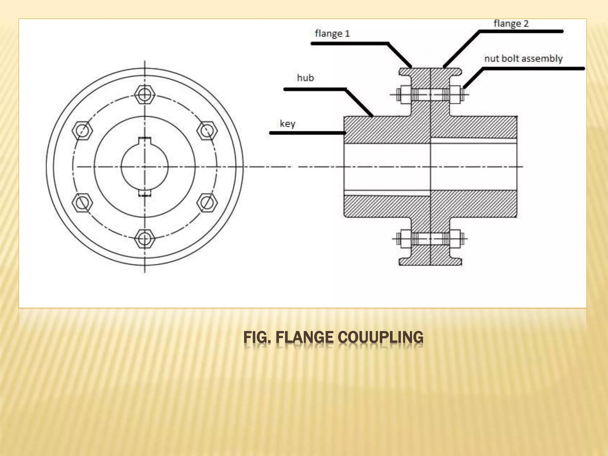
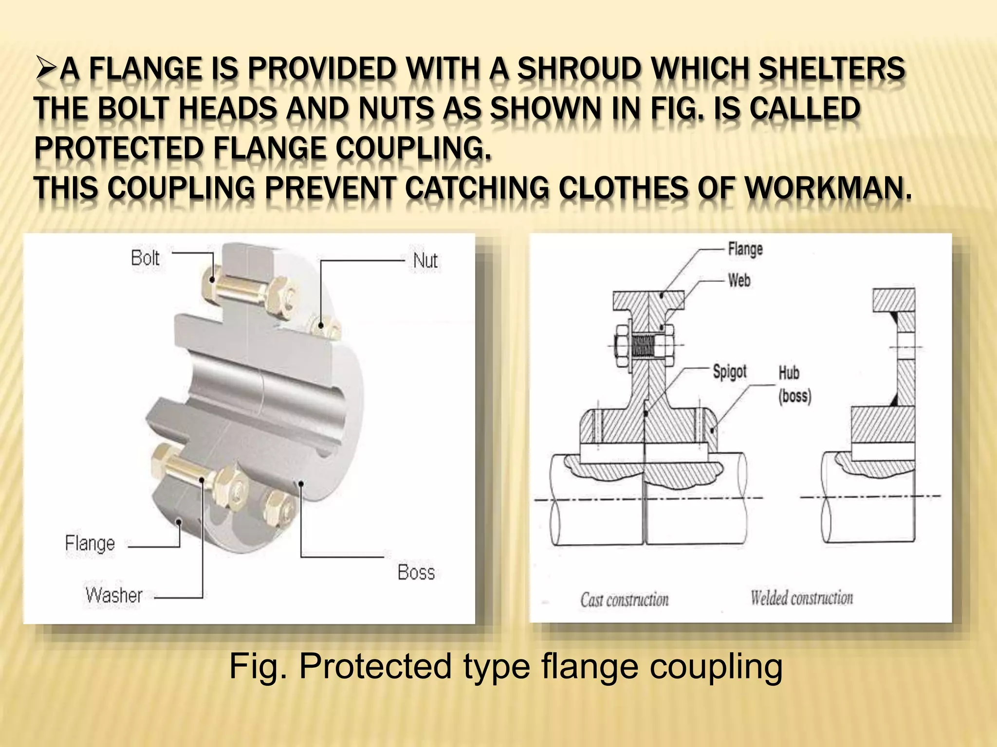
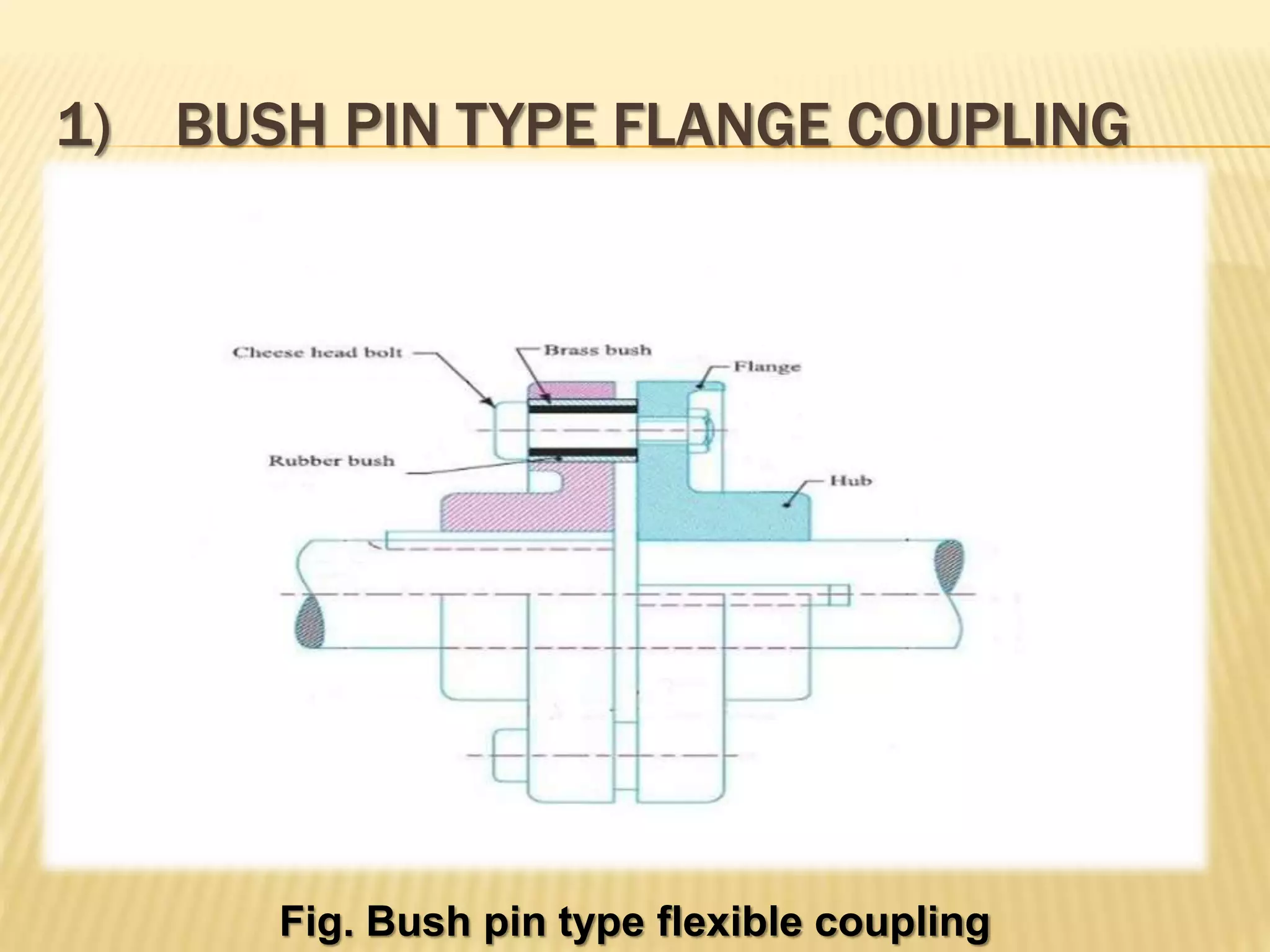
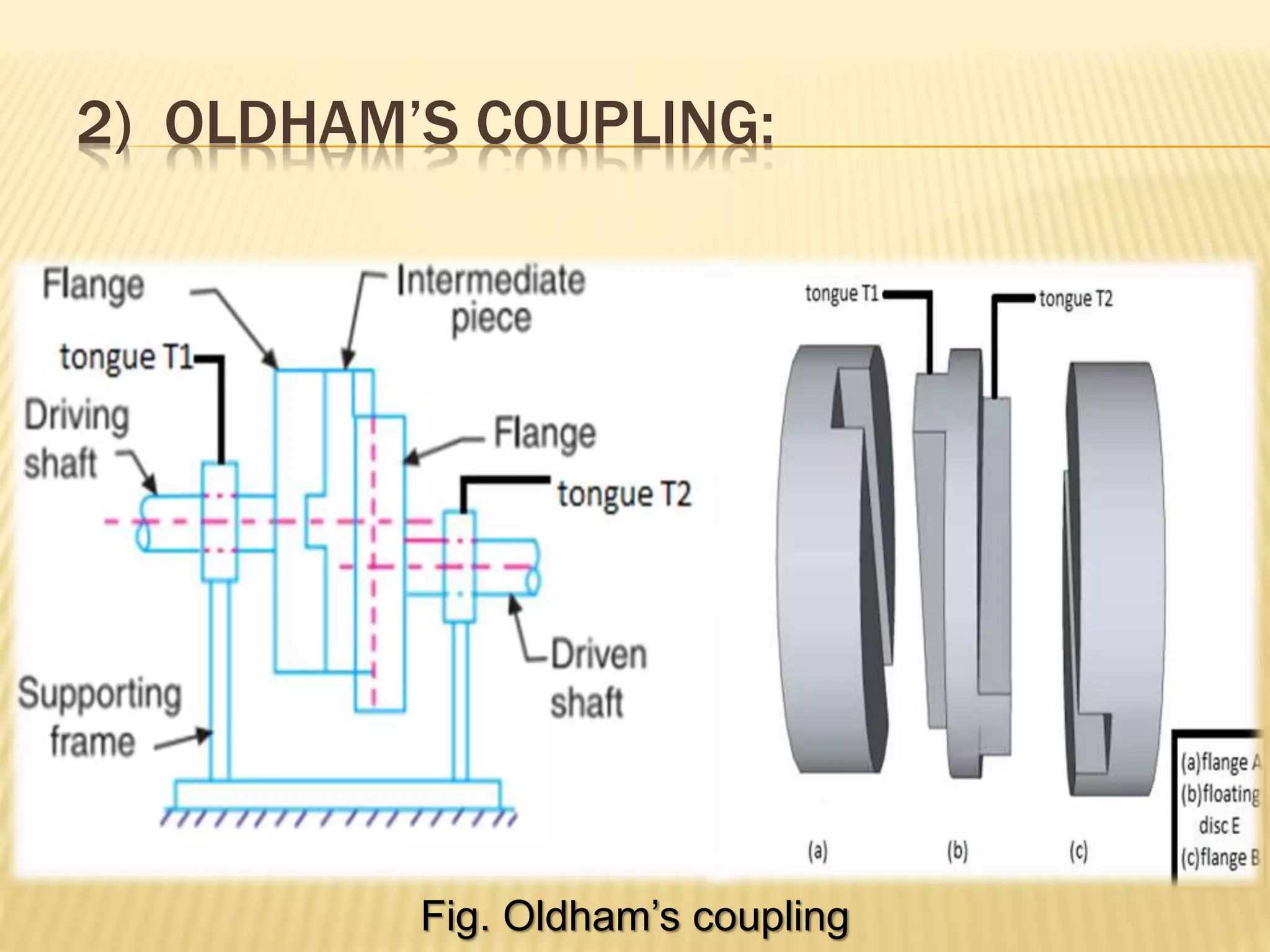
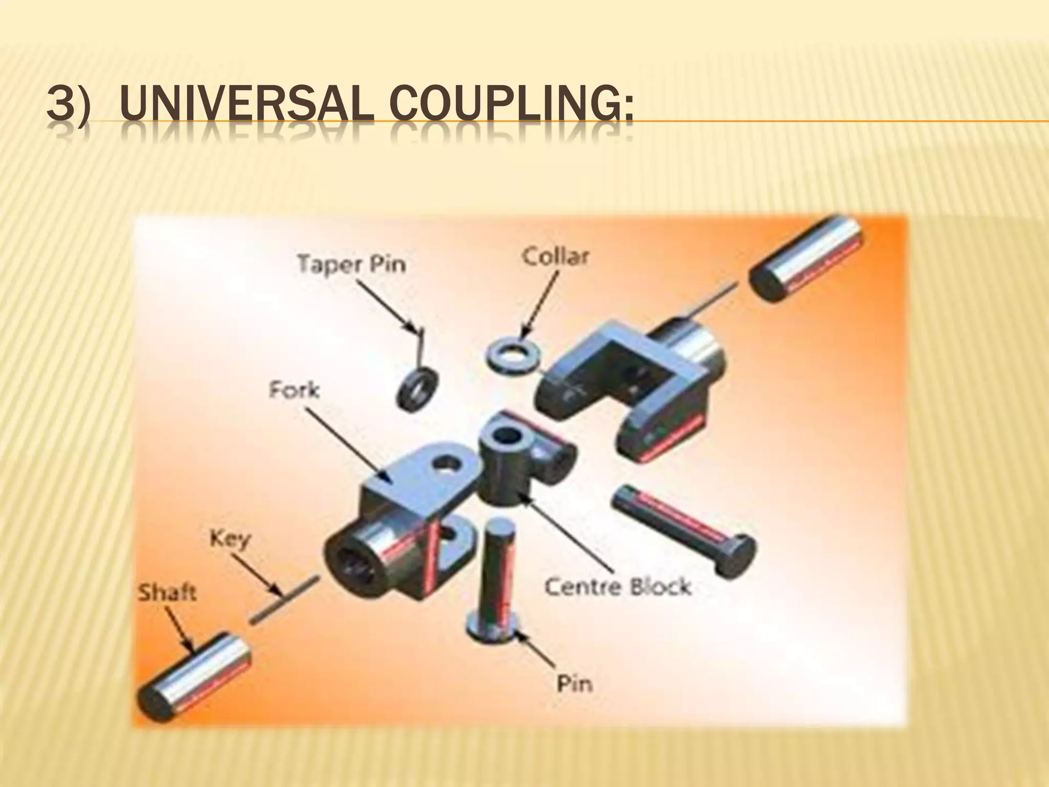
ELEMENTS OF MECHANICAL
ENGINEERING
Prepared by:-
Nikul pithva(m-36)
Shilay nilesh(m-37)
Guided by:-
Ravi sir
Flexible coupling and flange
coupling
COUPLING
Shaft are mostly available upto 7 metres
length due to transport difficulty.
To get a greater length , it is necessary to joint
two or more pieces of the shaft using coupling.
FLANGE COUPLING
This coupling is having two separate cast iron
flanges as shown in fig. A unprotected type
flange coupling .
Each flange is mounted on the shaft end and
keyed to it.
The two flanges are coupled together by help of
bolts and nuts.
The projected portion of one of the flange and
corresponding recess on other flange are help to
bring the shafts into line and to maintain
alignment.
FIG. FLANGE COUUPLING
A FLANGE IS PROVIDED WITH A SHROUD WHICH SHELTERS
THE BOLT HEADS AND NUTS AS SHOWN IN FIG. IS CALLED
PROTECTED FLANGE COUPLING.
THIS COUPLING PREVENT CATCHING CLOTHES OF WORKMAN.
Fig. Protected type flange coupling
This flange couplings is most accurate and
rigid.
This coupling provide the strong connection of
shafts.
It is used for heavy power transmission at low
speed.
FLEXIBLE COUPLING
This coupling is used to protect the driving and
driven machine members against harmful effects
produce due to misalignment of shafts, vibration,
sudden shock load or shaft expansion.
There are basic three types of flexible
coupling as follows:
1) Bushed pin type flange coupling :
 this type of coupling allows for imperfect
alignment of two joining shafts.
2) Oldham coupling:
 This type of coupling is used to join two
parllel shafts with small offset.
3) Universal coupling:
 This type of coupling is used to join two
intersecting shaft.
1) BUSH PIN TYPE FLANGE COUPLING
Fig. Bush pin type flexible coupling
this is modified form of protected type flange
coupling.
This type of coupling has a pins and it work as a
coupling bolts. the rubber or leather bushes are used
over the pins.
The coupling is having two halves are dissimilar in
construction as shown in fig.
The pins are rigidly fastened by nuts to one of the
flange and kept loose in the other flange.
This coupling is used for connection of shafts
which having the small parallel misalignment,
angular misalignment and axial displacement.
In this coupling rubber bush absorbs shocks
and vibration during its operation.
This type of coupling is mostly used to couple
an electric motor and machine.
2) OLDHAM’S COUPLING:
Fig. Oldham’s coupling
 It consists of two flange A and B with slots and a
central floating disc E as shown in fig.
The disc E having tongues T1 and T2 at right
angles. the tongue T1 is fitted into the slot of flange
A and allows horizontal sliding relative motion while
the tongue T2 is fitted into the slot of the flange B
and allows for vertical sliding relative motion.
This right angle motions of tongues on the slots
will accommodate lateral misalignment of shaft when
they rotate.
Oldham’s coupling is used in connecting two
parallel shafts but not in alignment, and their axis are
at small distance apart.
3) UNIVERSAL COUPLING:
These two forks are assembled to a central
block by pin.
A central block having two arms at right angle to
each other.
Universal coupling is used to connect two shafts
whose axis intersect.
It also used to connect two shafts, where the
angle between two shafts may be varied when
they rotate.
The universal coupling is widely used in
automobile and machine tools.
Eme(flecible coupling and flang coupling)

Eme(flecible coupling and flang coupling)

  • 1.
  • 2.
    Prepared by:- Nikul pithva(m-36) Shilaynilesh(m-37) Guided by:- Ravi sir Flexible coupling and flange coupling
  • 3.
    COUPLING Shaft are mostlyavailable upto 7 metres length due to transport difficulty. To get a greater length , it is necessary to joint two or more pieces of the shaft using coupling.
  • 4.
    FLANGE COUPLING This couplingis having two separate cast iron flanges as shown in fig. A unprotected type flange coupling . Each flange is mounted on the shaft end and keyed to it. The two flanges are coupled together by help of bolts and nuts. The projected portion of one of the flange and corresponding recess on other flange are help to bring the shafts into line and to maintain alignment.
  • 5.
  • 6.
    A FLANGE ISPROVIDED WITH A SHROUD WHICH SHELTERS THE BOLT HEADS AND NUTS AS SHOWN IN FIG. IS CALLED PROTECTED FLANGE COUPLING. THIS COUPLING PREVENT CATCHING CLOTHES OF WORKMAN. Fig. Protected type flange coupling
  • 7.
    This flange couplingsis most accurate and rigid. This coupling provide the strong connection of shafts. It is used for heavy power transmission at low speed.
  • 8.
    FLEXIBLE COUPLING This couplingis used to protect the driving and driven machine members against harmful effects produce due to misalignment of shafts, vibration, sudden shock load or shaft expansion.
  • 9.
    There are basicthree types of flexible coupling as follows: 1) Bushed pin type flange coupling :  this type of coupling allows for imperfect alignment of two joining shafts. 2) Oldham coupling:  This type of coupling is used to join two parllel shafts with small offset. 3) Universal coupling:  This type of coupling is used to join two intersecting shaft.
  • 10.
    1) BUSH PINTYPE FLANGE COUPLING Fig. Bush pin type flexible coupling
  • 11.
    this is modifiedform of protected type flange coupling. This type of coupling has a pins and it work as a coupling bolts. the rubber or leather bushes are used over the pins. The coupling is having two halves are dissimilar in construction as shown in fig. The pins are rigidly fastened by nuts to one of the flange and kept loose in the other flange.
  • 12.
    This coupling isused for connection of shafts which having the small parallel misalignment, angular misalignment and axial displacement. In this coupling rubber bush absorbs shocks and vibration during its operation. This type of coupling is mostly used to couple an electric motor and machine.
  • 13.
    2) OLDHAM’S COUPLING: Fig.Oldham’s coupling
  • 14.
     It consistsof two flange A and B with slots and a central floating disc E as shown in fig. The disc E having tongues T1 and T2 at right angles. the tongue T1 is fitted into the slot of flange A and allows horizontal sliding relative motion while the tongue T2 is fitted into the slot of the flange B and allows for vertical sliding relative motion. This right angle motions of tongues on the slots will accommodate lateral misalignment of shaft when they rotate. Oldham’s coupling is used in connecting two parallel shafts but not in alignment, and their axis are at small distance apart.
  • 15.
  • 16.
    These two forksare assembled to a central block by pin. A central block having two arms at right angle to each other. Universal coupling is used to connect two shafts whose axis intersect. It also used to connect two shafts, where the angle between two shafts may be varied when they rotate. The universal coupling is widely used in automobile and machine tools.