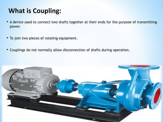
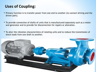
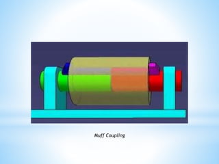
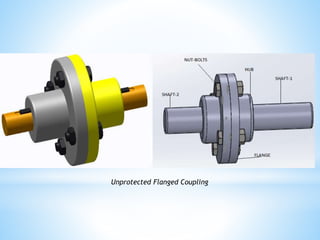
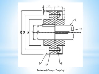
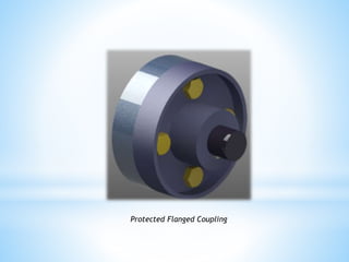
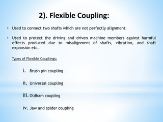
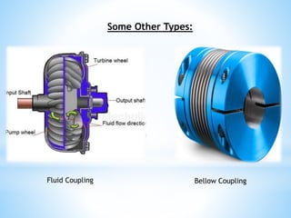
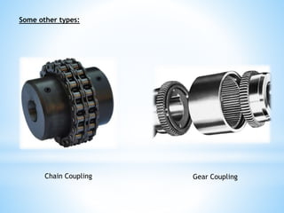
Couplings
Presented by: Usman Ghani (Mechanical Engineer)
Email: ugk557@gmail.com
Content of Presentation:
 What is Coupling
 Uses
 Types
 Coupling in our Workshop
 Good Coupling
 Coupling Maintenance
 Coupling Failures
 References
What is Coupling:
• A device used to connect two shafts together at their ends for the purpose of transmitting
power.
• To join two pieces of rotating equipment.
• Couplings do not normally allow disconnection of shafts during operation.
Uses of Coupling:
• Primary function is to transfer power from one end to another (to connect driving and the
driven part).
• To provide connection of shafts of units that is manufactured separately such as a motor
and generator and to provide for disconnection for repairs or alteration.
• To alter the vibration characteristics of rotating units and to reduce the transmission of
shock loads from one shaft to another.
Types of Coupling:
General Types of Couplings are:
1). Rigid Coupling for Aligned Shafts
2). Flexible Coupling for Non Aligned Shafts
1). Rigid Coupling:
Types of Rigid Couplings:
a). Muff Coupling
b). Clamp or Split Muff Coupling
c).Flanged Coupling
> Unprotected
> Protected
Used to connect two shafts which are perfectly axially aligned.
a). Muff Coupling:
 The simplest type of rigid coupling. Very simple to design and manufactured.
 It consist of a hollow cylinder whose inner diameter is same as that of shaft.
 It is fitted over the ends of two shafts by means of a sleeve/key.
 It can also be typed as keyed coupling by introducing a key between the cylinder and
shaft.
Muff Coupling
Muff Coupling
Muff Coupling
b). Split Muff Coupling:
• The cylinder is made into two halves parts and they are joined together by mean of
stud or nut bolts.
• Also Known as Clamp Coupling.
Split Muff Coupling
c). Flanged Coupling:
• This coupling has two separate flanges.
• Each flange is mounted on the shaft end and keyed to it. The two flanges are
coupled together by the help of bolts and nuts.
• The projected portion of one of the flange and corresponding recess on other flange
are help to bring the shafts into line and maintain alignment.
• Basically two types i.e. Unprotected and protected.
• Unprotected: The nut bolts are not protected.
•
• Protected: Flange is provided with shrouds which shelter the bolt heads and nuts.
This help in prevent catching the cloths of technicians.
Unprotected Flanged Coupling
Protected Flanged Coupling
2). Flexible Coupling:
Types of Flexible Couplings:
i. Brush pin coupling
ii. Universal coupling
iii.Oldham coupling
iv. Jaw and spider coupling
• Used to connect two shafts which are not perfectly alignment.
• Used to protect the driving and driven machine members against harmful
effects produced due to misalignment of shafts, vibration, and shaft
expansion etc.
i). Bush Pin Coupling:
Bush Pin Coupling
• It is modified form of flange coupling.
• This type of coupling has pins and the rubber bushes are used over the pins.
• The pins are rigidly fastened by nuts to one of the flange.
• This is used to connect small parallel misalignment and axial displacement.
• In this coupling rubber bushes absorb shocks and vibration during its operation.
Bush Pin Coupling:
ii). Universal Coupling:
• It consist of two similar forks keyed on the ends of the two shafts, assembled to a
central block by pin.
• It is used where the angle between two shafts may be varied when they rotate.
• It is widely used in automobile and machine tools.
• Also called as universal joint or U – joint.
Universal Coupling
Oldham’s Coupling
iii). Oldham’s Coupling:
Oldham’s Coupling:
• It consist of two flanges with slots and a central floating disc.
• The disc having two tongues at right angles. The one tongue is fitted into the slot
of first flange and allow horizontal sliding relative motion with other tongue is
fitted into the slot of second flange and allow for vertical sliding relative motion.
• This type of coupling can be used in connecting two parallel but not aligned shaft
with their axis are at smaller distance apart.
iii). Jaw and Spider Coupling:
Jaw and Spider Coupling:
• It is designed to transmit torque (by connecting two shafts) while damping system
vibrations and accommodating misalignment, which protects other components
from damage.
• Jaw couplings are composed of three parts: two metallic hubs and
an elastomer insert called an element (commonly referred to as a spider).
• Jaw coupling torque is transmitted through the elastomer lobes in compression.
Some Other Types:
Fluid Coupling Bellow Coupling
Some other types:
Chain Coupling Gear Coupling
Coupling in our Workshop:
Quiz:
Name the following coupling
• It should be easy to connect or disconnect.
• It should transmit full power from one shaft to another without any losses.
• It should hold the shaft in perfect alignment.
• It should reduce the transmission of shock loads from one shaft to another.
Good Coupling:
• Performing visual inspection
• Checking for sign of wear
• Cleaning the coupling regularly if it is exposed to dust
• Checking and changing lubricant regularly if lubricant is used
• Documenting the maintenance performed
Coupling Maintenance:
• Improper installation
• Bad selections
• Operating beyond design capabilities
• Excessive wobbling and vibrations
Coupling Failures:
• A Textbook of Machine Design by RS Khurmi and JK Gupta
• Elements of Mechanical Engineering by SM BHATT
• Wikipedia and photos from google.
References:
Thanks

Coupling (Simplest PPT)

  • 1.
    Couplings Presented by: UsmanGhani (Mechanical Engineer) Email: ugk557@gmail.com
  • 2.
    Content of Presentation: What is Coupling  Uses  Types  Coupling in our Workshop  Good Coupling  Coupling Maintenance  Coupling Failures  References
  • 3.
    What is Coupling: •A device used to connect two shafts together at their ends for the purpose of transmitting power. • To join two pieces of rotating equipment. • Couplings do not normally allow disconnection of shafts during operation.
  • 4.
    Uses of Coupling: •Primary function is to transfer power from one end to another (to connect driving and the driven part). • To provide connection of shafts of units that is manufactured separately such as a motor and generator and to provide for disconnection for repairs or alteration. • To alter the vibration characteristics of rotating units and to reduce the transmission of shock loads from one shaft to another.
  • 5.
    Types of Coupling: GeneralTypes of Couplings are: 1). Rigid Coupling for Aligned Shafts 2). Flexible Coupling for Non Aligned Shafts
  • 6.
    1). Rigid Coupling: Typesof Rigid Couplings: a). Muff Coupling b). Clamp or Split Muff Coupling c).Flanged Coupling > Unprotected > Protected Used to connect two shafts which are perfectly axially aligned.
  • 7.
    a). Muff Coupling: The simplest type of rigid coupling. Very simple to design and manufactured.  It consist of a hollow cylinder whose inner diameter is same as that of shaft.  It is fitted over the ends of two shafts by means of a sleeve/key.  It can also be typed as keyed coupling by introducing a key between the cylinder and shaft.
  • 8.
  • 9.
  • 10.
  • 11.
    b). Split MuffCoupling: • The cylinder is made into two halves parts and they are joined together by mean of stud or nut bolts. • Also Known as Clamp Coupling. Split Muff Coupling
  • 12.
    c). Flanged Coupling: •This coupling has two separate flanges. • Each flange is mounted on the shaft end and keyed to it. The two flanges are coupled together by the help of bolts and nuts. • The projected portion of one of the flange and corresponding recess on other flange are help to bring the shafts into line and maintain alignment. • Basically two types i.e. Unprotected and protected. • Unprotected: The nut bolts are not protected. • • Protected: Flange is provided with shrouds which shelter the bolt heads and nuts. This help in prevent catching the cloths of technicians.
  • 13.
  • 14.
  • 15.
  • 16.
  • 17.
    2). Flexible Coupling: Typesof Flexible Couplings: i. Brush pin coupling ii. Universal coupling iii.Oldham coupling iv. Jaw and spider coupling • Used to connect two shafts which are not perfectly alignment. • Used to protect the driving and driven machine members against harmful effects produced due to misalignment of shafts, vibration, and shaft expansion etc.
  • 18.
    i). Bush PinCoupling: Bush Pin Coupling
  • 19.
    • It ismodified form of flange coupling. • This type of coupling has pins and the rubber bushes are used over the pins. • The pins are rigidly fastened by nuts to one of the flange. • This is used to connect small parallel misalignment and axial displacement. • In this coupling rubber bushes absorb shocks and vibration during its operation. Bush Pin Coupling:
  • 20.
    ii). Universal Coupling: •It consist of two similar forks keyed on the ends of the two shafts, assembled to a central block by pin. • It is used where the angle between two shafts may be varied when they rotate. • It is widely used in automobile and machine tools. • Also called as universal joint or U – joint.
  • 21.
  • 22.
  • 23.
    Oldham’s Coupling: • Itconsist of two flanges with slots and a central floating disc. • The disc having two tongues at right angles. The one tongue is fitted into the slot of first flange and allow horizontal sliding relative motion with other tongue is fitted into the slot of second flange and allow for vertical sliding relative motion. • This type of coupling can be used in connecting two parallel but not aligned shaft with their axis are at smaller distance apart.
  • 24.
    iii). Jaw andSpider Coupling:
  • 25.
    Jaw and SpiderCoupling: • It is designed to transmit torque (by connecting two shafts) while damping system vibrations and accommodating misalignment, which protects other components from damage. • Jaw couplings are composed of three parts: two metallic hubs and an elastomer insert called an element (commonly referred to as a spider). • Jaw coupling torque is transmitted through the elastomer lobes in compression.
  • 26.
    Some Other Types: FluidCoupling Bellow Coupling
  • 27.
    Some other types: ChainCoupling Gear Coupling
  • 28.
    Coupling in ourWorkshop: Quiz: Name the following coupling
  • 30.
    • It shouldbe easy to connect or disconnect. • It should transmit full power from one shaft to another without any losses. • It should hold the shaft in perfect alignment. • It should reduce the transmission of shock loads from one shaft to another. Good Coupling:
  • 31.
    • Performing visualinspection • Checking for sign of wear • Cleaning the coupling regularly if it is exposed to dust • Checking and changing lubricant regularly if lubricant is used • Documenting the maintenance performed Coupling Maintenance:
  • 32.
    • Improper installation •Bad selections • Operating beyond design capabilities • Excessive wobbling and vibrations Coupling Failures:
  • 33.
    • A Textbookof Machine Design by RS Khurmi and JK Gupta • Elements of Mechanical Engineering by SM BHATT • Wikipedia and photos from google. References:
  • 34.