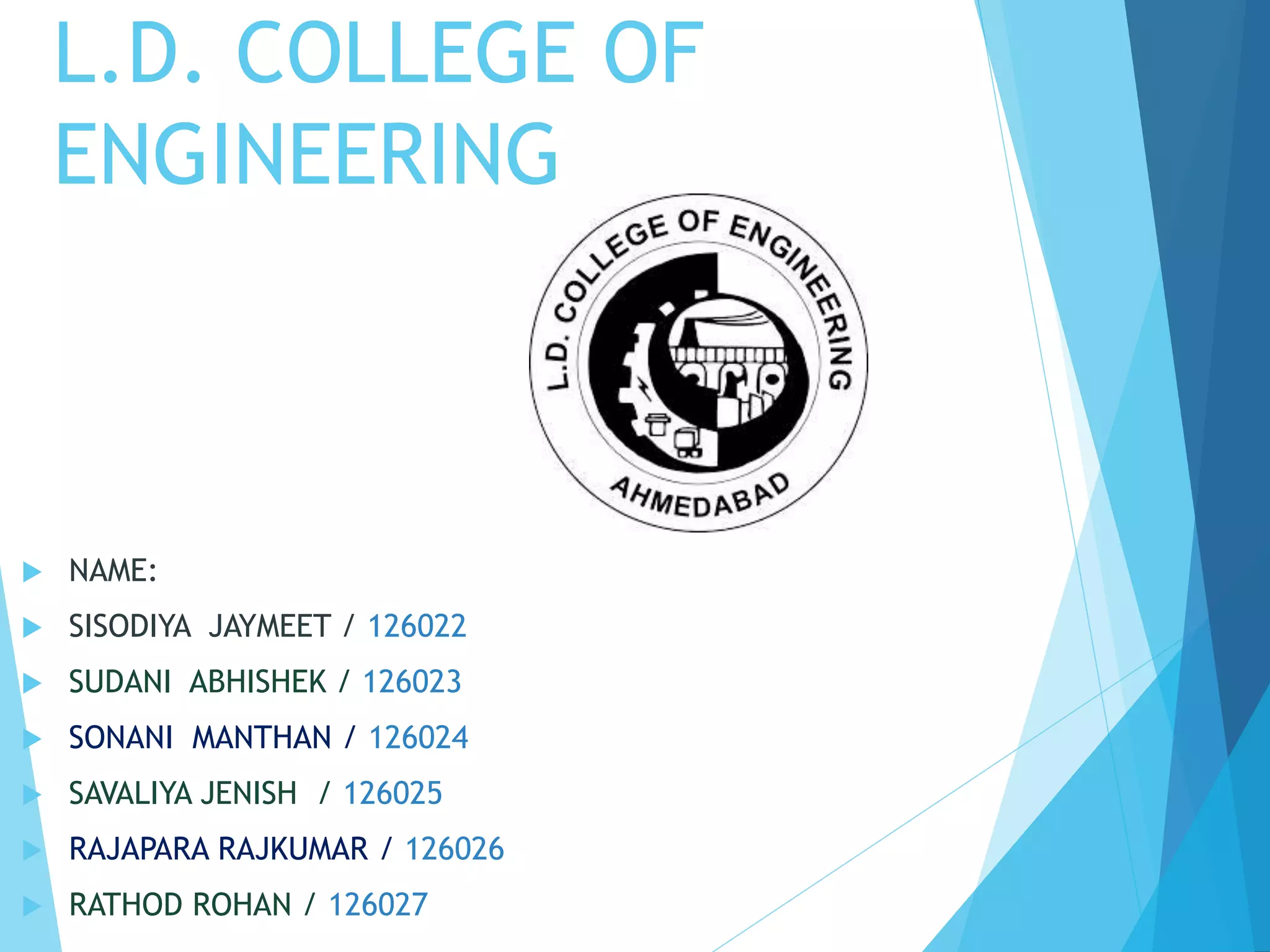
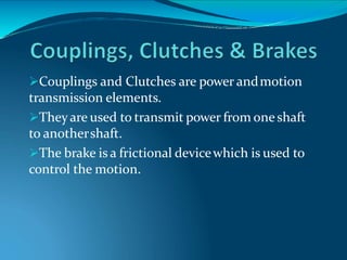
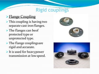
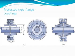
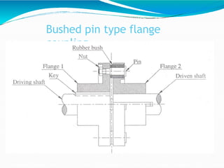
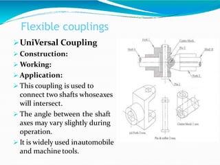
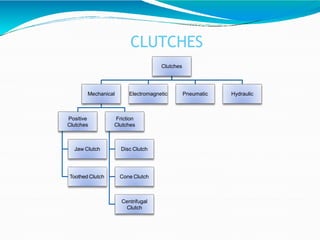
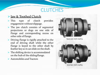
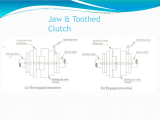
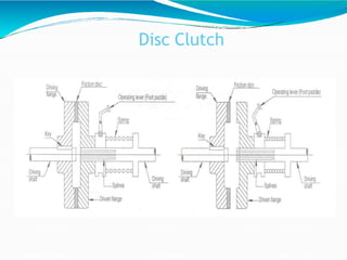
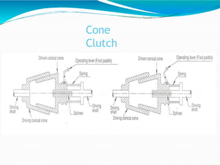
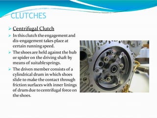
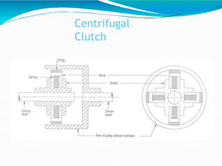
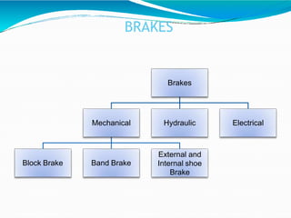
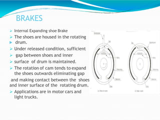
L.D. COLLEGE OF
ENGINEERING
 NAME:
 SISODIYA JAYMEET / 126022
 SUDANI ABHISHEK / 126023
 SONANI MANTHAN / 126024
 SAVALIYA JENISH / 126025
 RAJAPARA RAJKUMAR / 126026
 RATHOD ROHAN / 126027
Couplings and Clutches are power andmotion
transmission elements.
Theyare used to transmit power from one shaft
to anothershaft.
The brake is a frictional devicewhich is used to
control the motion.
Classification of
Couplings
Couplings
Rigid
Coupling
Sleeve or Muff
Coupling
Split Muff
Coupling
Flange
Coupling
Flexible
Coupling
Bushed pin type
flange
Coupling
Oldham
Coupling
Universal
Coupling
Rigid
couplings
 Rigid Couplingsare used toconnect two shafts which are
perfectly in axialalignment.
Sleeve or Muff Coupling
 Construction:
 It is the simplest typeof rigid coupling which is made from
cast iron.
 The hollow cylinder (muff) is fitted overtheendsof the two
shaftswith the helpof tapersunk key.
 Working:
 Disadvantage: It is difficult toassemblewhen there is no
perfect alignment betweenshafts.
Sleeve or Muff
Coupling
Rigid couplings
Split Muff Coupling
 Construction:
 The muff orsleeve is made into two halves of cast iron.
 They both are joined by nut andbolts.
 Advantage:
 Assembling and disassembling of the coupling ispossible
without the changing the position ofshaft.
 Application:
 This coupling is used for heavy powertransmission at
moderatespeed.
Split Muff
Coupling
Rigid couplings
Flange Coupling
 This coupling is havingtwo
separate cast ironflanges.
 The flanges can beof
protected type or
unprotected type.
 The flange couplingsare
rigid and accurate.
 It is used for heavypower
transmission at lowspeed.
Protected type flange
couplings
Flexible couplings
 Flexible couplings are used to protect the driving and
driven machines from effect of shocks, excessivestresses
due to deflection and vibration which may arise from
misalignment of shafts.
Bushed pin type flangecoupling
 This typeof coupling allows for imperfectalignmentof two
joining shaft.
 This typeof coupling has pins which works as acoupling
bolt. The rubberor leather bushes are used overpins.
 Rubber bushabsorbs shocks and vibrationsduring
operation.
 It isgenerally used tocoupleelectric motorand machine.
Bushed pin type flange
coupling
Flexible couplings
Oldham’s Coupling
 It is used in connecting two
parallel shafts whose axesare
at small distanceapart.
 The flanges have projections
and disc is provided with two
slots on both sides which are
right angle to eachother.
 The rotation of drive shaft
causes the rotation andsliding
of disc which transmits the
motion and power to the
driven shaft.
Flexible couplings
UniVersal Coupling
 Construction:
 Working:
 Application:
 This coupling is used to
connect two shafts whoseaxes
will intersect.
 The angle between the shaft
axes may vary slightly during
operation.
 It is widely used inautomobile
and machine tools.
CLUTCHES
Clutch is a form of coupling which is used to
transmit the power from driver shaft or an input
shaft to driven shaft of machine which may be
required to start or stopfrequently.
CLUTCHES
Clutches
Mechanical
Positive
Clutches
Jaw Clutch
Toothed Clutch
Friction
Clutches
Disc Clutch
Cone Clutch
Centrifugal
Clutch
Electromagnetic Pneumatic Hydraulic
CLUTCHES
 Jaw & Toothed Clutch
 This type of clutch provides
engagement withoutslippage.
 The jaw clutch consists of segmental
projections or dogs on one side of
flange and corresponding recess on
other side of flange.
 Driving flange is rigidly attached to the
end of driving shaft while the other
flange is keyed to the other shaft by
feather keyso it can slide on the shaft.
 The shifting device is accommodated
on the hub of the slidingflange.
 Automobiles and Tractors
Jaw & Toothed
Clutch
CLUTCHES
Disc Clutch
 Thereare two flanges in such typeof clutches.
 One rigidly keyed todriving shaftand other fitted todriven
shaft by feather key orsplines.
 The amount of torque transmitted depends upon axial
pressure, radiusof the friction surfaces and coefficientof
friction.
 Automobiles
 When large torque transmission is required themultidisc
clutches are used. It is having more number of contact
surfaces discs on driving and driven shaft.
Disc Clutch
CLUTCH
Cone Clutch
 Theclutch consists of an internal cone fixed to thedriving
member and a movable cone free to slide axially is keyed
to the drivenmember.
 The slope of cone is from 8º to15º.
 Theclutch parts are held together by springs producing
required axial force.
 Advantage of cone clutch over the disc clutch is very
simpleand required less axial pressure todisengaged the
clutch.
Cone
Clutch
CLUTCHES
 Centrifugal Clutch
 In thisclutch theengagementand
dis-engagement takes place at
certain runningspeed.
 Theshoes are held against the hub
or spider on the driving shaft by
means of suitablesprings.
 The driven member consists of a
cylindrical drum in which shoes
slide to make the contact through
friction surfaces with inner linings
of drum due tocentrifugal forceon
the shoes.
Centrifugal
Clutch
BRAKES
It is a device by means of which frictional
resistance is applied to a moving machinemember
in order to retard orstop the motion of a machine.
Brakes are used in automobiles, trains,vehicles,
hoists, elevators, presses, etc.
Brakes absorbs kinetic energy of movingmember
in automobiles and brakes absorbs potential
energy of lowering member in hoists or elevator
brake.
BRAKES
Brakes
Mechanical
Block Brake Band Brake
External and
Internal shoe
Brake
Hydraulic Electrical
BRAKES
Block Brake
 This brake consists of blocks which are pressed against
the rim of revolving brake wheel ordrum.
 The friction between thewheel and the blocks tend to
prevent the rotation of thewheel.
 Single Block :Railway train, Tram. Prony brake isan
example of block brake.
 Double block :Electriccranes.
 Bicycle brake isan exampleof double block brake.
BRAKES
Band Brake
 A band brake consists of a flexible
band of leatheror steel
lined with friction material.
 The friction between the band
and the wheel surface provides
the braking force todecrease or
stop the motion of the wheel.
 This type of brakes are used in
 civil construction equipmentsand also in
automobiles as hand brake.
BRAKES
 Internal Expanding shoe Brake
 The shoes are housed in the rotating
 drum.
 Under released condition, sufficient
 gap between shoes and inner
 surface of drum is maintained.
 The rotation of cam tends to expand
the shoes outwards eliminating gap
and making contact between the shoes
and inner surface of the rotating drum.
 Applications are in motor cars and
light trucks.
Coupling clutch brake for mechanical engineering

Coupling clutch brake for mechanical engineering

  • 1.
    L.D. COLLEGE OF ENGINEERING NAME:  SISODIYA JAYMEET / 126022  SUDANI ABHISHEK / 126023  SONANI MANTHAN / 126024  SAVALIYA JENISH / 126025  RAJAPARA RAJKUMAR / 126026  RATHOD ROHAN / 126027
  • 2.
    Couplings and Clutchesare power andmotion transmission elements. Theyare used to transmit power from one shaft to anothershaft. The brake is a frictional devicewhich is used to control the motion.
  • 3.
    Classification of Couplings Couplings Rigid Coupling Sleeve orMuff Coupling Split Muff Coupling Flange Coupling Flexible Coupling Bushed pin type flange Coupling Oldham Coupling Universal Coupling
  • 4.
    Rigid couplings  Rigid Couplingsareused toconnect two shafts which are perfectly in axialalignment. Sleeve or Muff Coupling  Construction:  It is the simplest typeof rigid coupling which is made from cast iron.  The hollow cylinder (muff) is fitted overtheendsof the two shaftswith the helpof tapersunk key.  Working:  Disadvantage: It is difficult toassemblewhen there is no perfect alignment betweenshafts.
  • 5.
  • 6.
    Rigid couplings Split MuffCoupling  Construction:  The muff orsleeve is made into two halves of cast iron.  They both are joined by nut andbolts.  Advantage:  Assembling and disassembling of the coupling ispossible without the changing the position ofshaft.  Application:  This coupling is used for heavy powertransmission at moderatespeed.
  • 7.
  • 8.
    Rigid couplings Flange Coupling This coupling is havingtwo separate cast ironflanges.  The flanges can beof protected type or unprotected type.  The flange couplingsare rigid and accurate.  It is used for heavypower transmission at lowspeed.
  • 9.
  • 10.
    Flexible couplings  Flexiblecouplings are used to protect the driving and driven machines from effect of shocks, excessivestresses due to deflection and vibration which may arise from misalignment of shafts. Bushed pin type flangecoupling  This typeof coupling allows for imperfectalignmentof two joining shaft.  This typeof coupling has pins which works as acoupling bolt. The rubberor leather bushes are used overpins.  Rubber bushabsorbs shocks and vibrationsduring operation.  It isgenerally used tocoupleelectric motorand machine.
  • 11.
    Bushed pin typeflange coupling
  • 12.
    Flexible couplings Oldham’s Coupling It is used in connecting two parallel shafts whose axesare at small distanceapart.  The flanges have projections and disc is provided with two slots on both sides which are right angle to eachother.  The rotation of drive shaft causes the rotation andsliding of disc which transmits the motion and power to the driven shaft.
  • 13.
    Flexible couplings UniVersal Coupling Construction:  Working:  Application:  This coupling is used to connect two shafts whoseaxes will intersect.  The angle between the shaft axes may vary slightly during operation.  It is widely used inautomobile and machine tools.
  • 14.
    CLUTCHES Clutch is aform of coupling which is used to transmit the power from driver shaft or an input shaft to driven shaft of machine which may be required to start or stopfrequently.
  • 15.
    CLUTCHES Clutches Mechanical Positive Clutches Jaw Clutch Toothed Clutch Friction Clutches DiscClutch Cone Clutch Centrifugal Clutch Electromagnetic Pneumatic Hydraulic
  • 16.
    CLUTCHES  Jaw &Toothed Clutch  This type of clutch provides engagement withoutslippage.  The jaw clutch consists of segmental projections or dogs on one side of flange and corresponding recess on other side of flange.  Driving flange is rigidly attached to the end of driving shaft while the other flange is keyed to the other shaft by feather keyso it can slide on the shaft.  The shifting device is accommodated on the hub of the slidingflange.  Automobiles and Tractors
  • 17.
  • 18.
    CLUTCHES Disc Clutch  Therearetwo flanges in such typeof clutches.  One rigidly keyed todriving shaftand other fitted todriven shaft by feather key orsplines.  The amount of torque transmitted depends upon axial pressure, radiusof the friction surfaces and coefficientof friction.  Automobiles  When large torque transmission is required themultidisc clutches are used. It is having more number of contact surfaces discs on driving and driven shaft.
  • 19.
  • 20.
    CLUTCH Cone Clutch  Theclutchconsists of an internal cone fixed to thedriving member and a movable cone free to slide axially is keyed to the drivenmember.  The slope of cone is from 8º to15º.  Theclutch parts are held together by springs producing required axial force.  Advantage of cone clutch over the disc clutch is very simpleand required less axial pressure todisengaged the clutch.
  • 21.
  • 22.
    CLUTCHES  Centrifugal Clutch In thisclutch theengagementand dis-engagement takes place at certain runningspeed.  Theshoes are held against the hub or spider on the driving shaft by means of suitablesprings.  The driven member consists of a cylindrical drum in which shoes slide to make the contact through friction surfaces with inner linings of drum due tocentrifugal forceon the shoes.
  • 23.
  • 24.
    BRAKES It is adevice by means of which frictional resistance is applied to a moving machinemember in order to retard orstop the motion of a machine. Brakes are used in automobiles, trains,vehicles, hoists, elevators, presses, etc. Brakes absorbs kinetic energy of movingmember in automobiles and brakes absorbs potential energy of lowering member in hoists or elevator brake.
  • 25.
    BRAKES Brakes Mechanical Block Brake BandBrake External and Internal shoe Brake Hydraulic Electrical
  • 26.
    BRAKES Block Brake  Thisbrake consists of blocks which are pressed against the rim of revolving brake wheel ordrum.  The friction between thewheel and the blocks tend to prevent the rotation of thewheel.  Single Block :Railway train, Tram. Prony brake isan example of block brake.  Double block :Electriccranes.  Bicycle brake isan exampleof double block brake.
  • 28.
    BRAKES Band Brake  Aband brake consists of a flexible band of leatheror steel lined with friction material.  The friction between the band and the wheel surface provides the braking force todecrease or stop the motion of the wheel.  This type of brakes are used in  civil construction equipmentsand also in automobiles as hand brake.
  • 29.
    BRAKES  Internal Expandingshoe Brake  The shoes are housed in the rotating  drum.  Under released condition, sufficient  gap between shoes and inner  surface of drum is maintained.  The rotation of cam tends to expand the shoes outwards eliminating gap and making contact between the shoes and inner surface of the rotating drum.  Applications are in motor cars and light trucks.