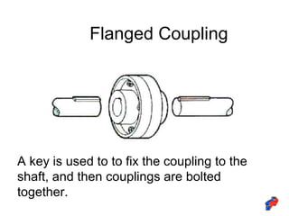
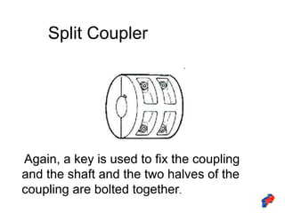
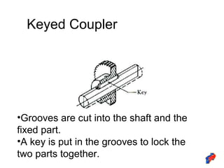
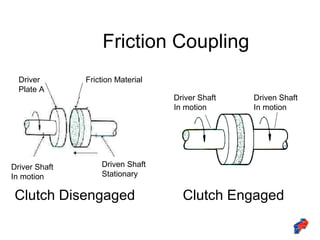
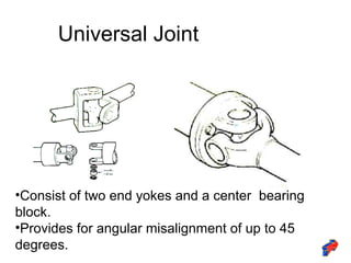
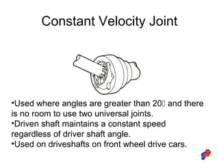
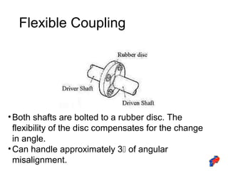
Forging new generations of engineers
Couplings
• A device that is used to connect two shafts
together for the purpose of power
transmission.
• General types of couplings are:
–rigid: for aligned shafts
–flexible: for non-aligned shafts
Aligned Shaft Couplings
• Aligned shaft couplings are rigid couplings
that are designed to draw two shafts
together so that no motion can occur
between them.
• Types
–Flanged
–Split Coupler
–Keyed
–Friction
Flanged Coupling
A key is used to to fix the coupling to the
shaft, and then couplings are bolted
together.
Split Coupler
Again, a key is used to fix the coupling
and the shaft and the two halves of the
coupling are bolted together.
Keyed Coupler
•Grooves are cut into the shaft and the
fixed part.
•A key is put in the grooves to lock the
two parts together.
Friction Coupling
Clutch Disengaged Clutch Engaged
Driver
Plate A
Friction Material
Driven Shaft
Stationary
Driver Shaft
In motion
Driver Shaft
In motion
Driven Shaft
In motion
Non-Aligned Shaft Couplings
• Used to join shafts that meet at a slight
angle.
• Angle may still change while running due
to vibration or load.
• Types:
–Universal
–Constant Velocity
–Flexible
Universal Joint
•Consist of two end yokes and a center bearing
block.
•Provides for angular misalignment of up to 45
degrees.
Constant Velocity Joint
•Used where angles are greater than 20 and there
is no room to use two universal joints.
•Driven shaft maintains a constant speed
regardless of driver shaft angle.
•Used on driveshafts on front wheel drive cars.
Flexible Coupling
•Both shafts are bolted to a rubber disc. The
flexibility of the disc compensates for the change
in angle.
•Can handle approximately 3 of angular
misalignment.

Couplings

  • 1.
  • 2.
    Couplings • A devicethat is used to connect two shafts together for the purpose of power transmission. • General types of couplings are: –rigid: for aligned shafts –flexible: for non-aligned shafts
  • 3.
    Aligned Shaft Couplings •Aligned shaft couplings are rigid couplings that are designed to draw two shafts together so that no motion can occur between them. • Types –Flanged –Split Coupler –Keyed –Friction
  • 4.
    Flanged Coupling A keyis used to to fix the coupling to the shaft, and then couplings are bolted together.
  • 5.
    Split Coupler Again, akey is used to fix the coupling and the shaft and the two halves of the coupling are bolted together.
  • 6.
    Keyed Coupler •Grooves arecut into the shaft and the fixed part. •A key is put in the grooves to lock the two parts together.
  • 7.
    Friction Coupling Clutch DisengagedClutch Engaged Driver Plate A Friction Material Driven Shaft Stationary Driver Shaft In motion Driver Shaft In motion Driven Shaft In motion
  • 8.
    Non-Aligned Shaft Couplings •Used to join shafts that meet at a slight angle. • Angle may still change while running due to vibration or load. • Types: –Universal –Constant Velocity –Flexible
  • 9.
    Universal Joint •Consist oftwo end yokes and a center bearing block. •Provides for angular misalignment of up to 45 degrees.
  • 10.
    Constant Velocity Joint •Usedwhere angles are greater than 20 and there is no room to use two universal joints. •Driven shaft maintains a constant speed regardless of driver shaft angle. •Used on driveshafts on front wheel drive cars.
  • 11.
    Flexible Coupling •Both shaftsare bolted to a rubber disc. The flexibility of the disc compensates for the change in angle. •Can handle approximately 3 of angular misalignment.