The document provides solutions to exercises on modeling an elevator control system using UML diagrams. It includes:
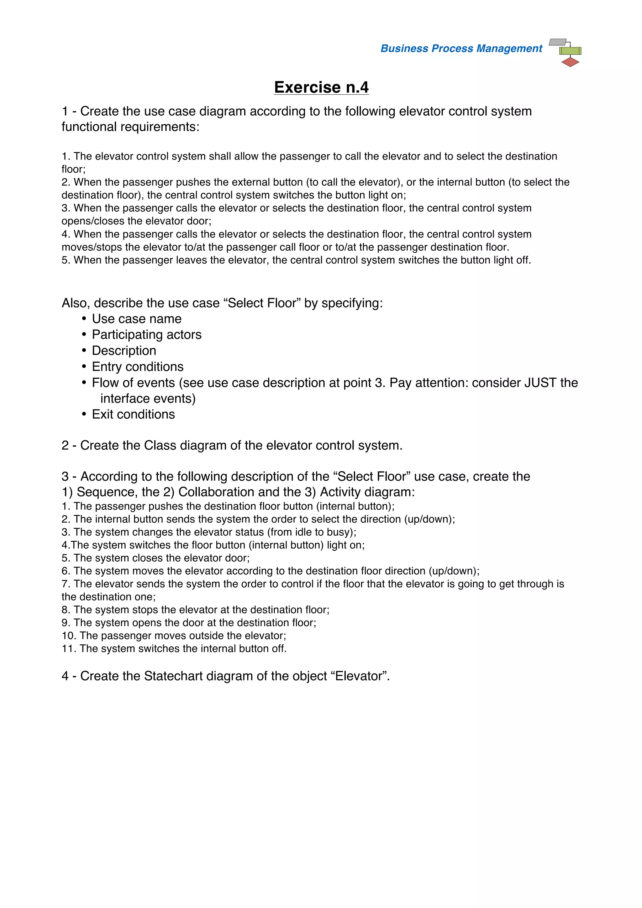
1) A use case diagram showing passengers calling and selecting floors and the system opening/closing doors and moving elevators.
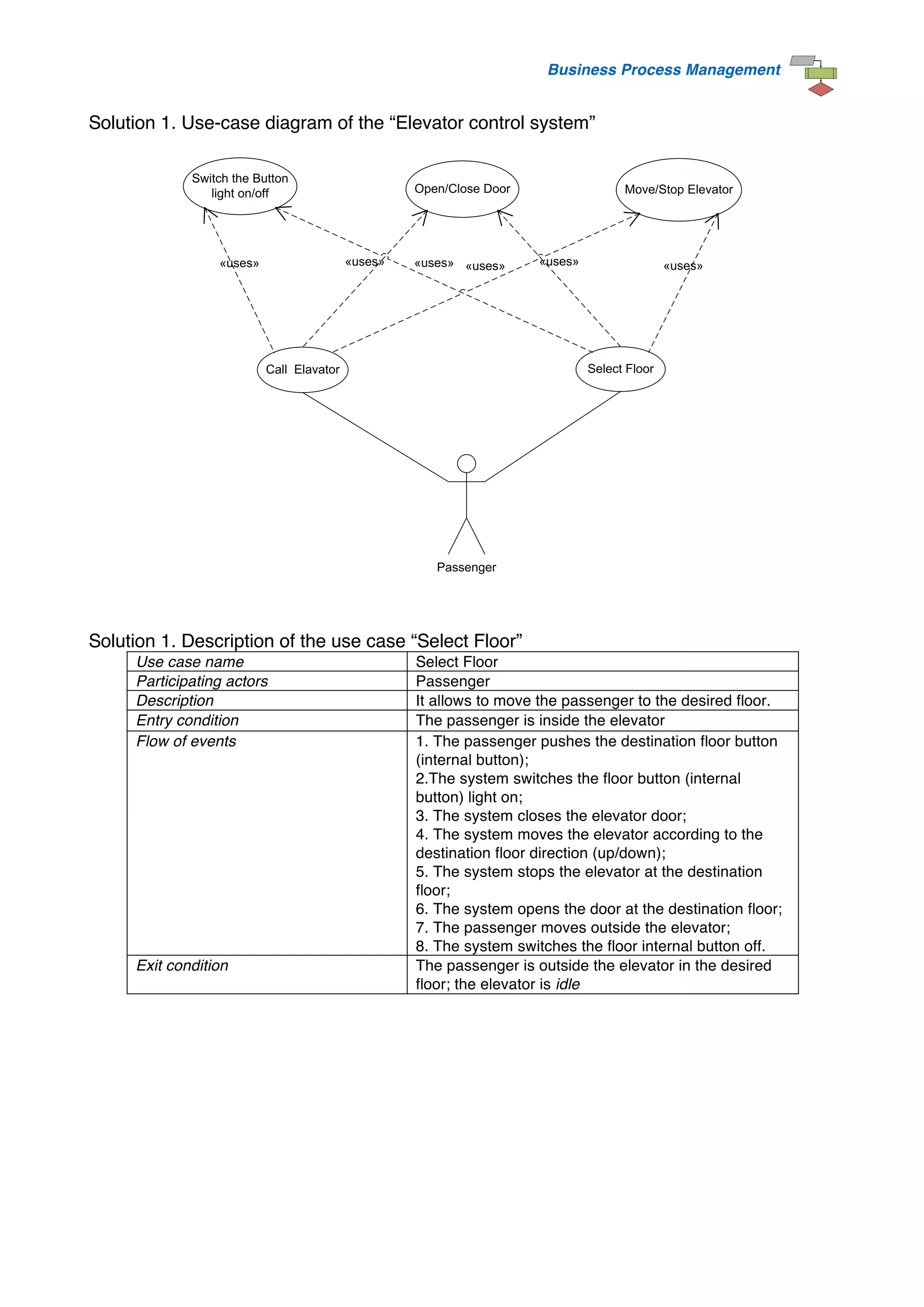
2) A class diagram of the elevator control system with classes like central control system, buttons, elevator, and door.
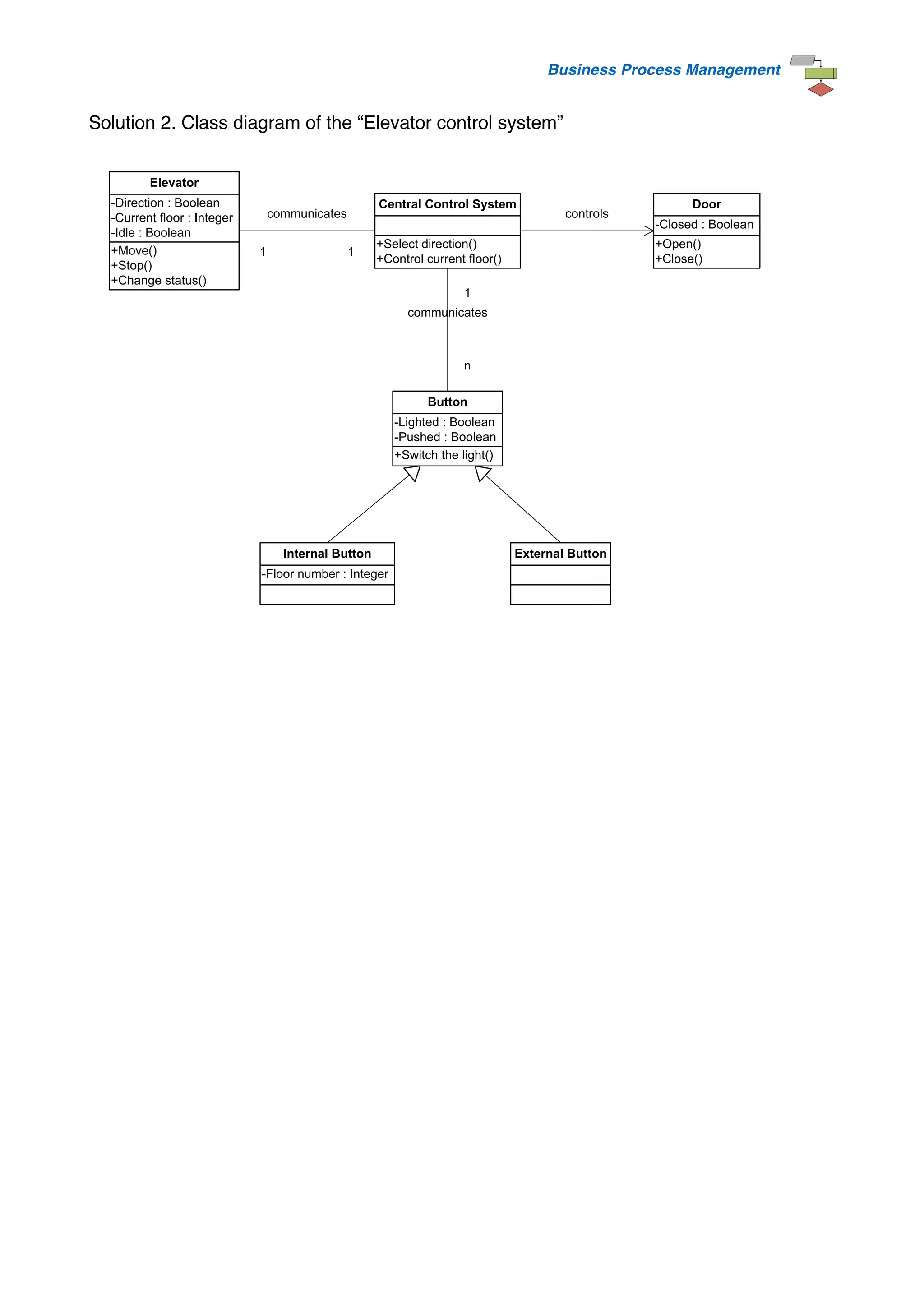
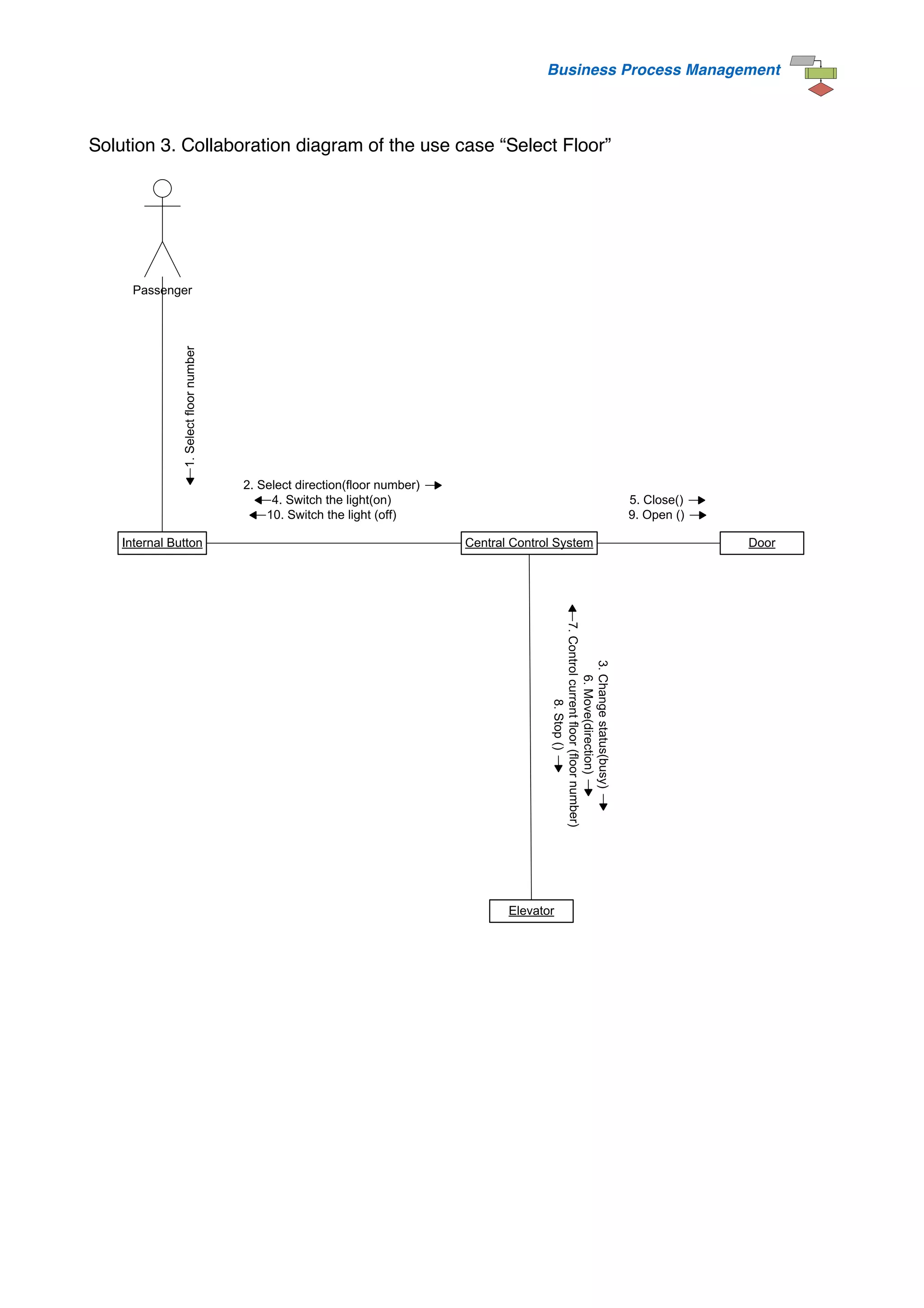
3) Sequence, collaboration, and activity diagrams modeling the "Select Floor" use case showing passenger and system interactions.
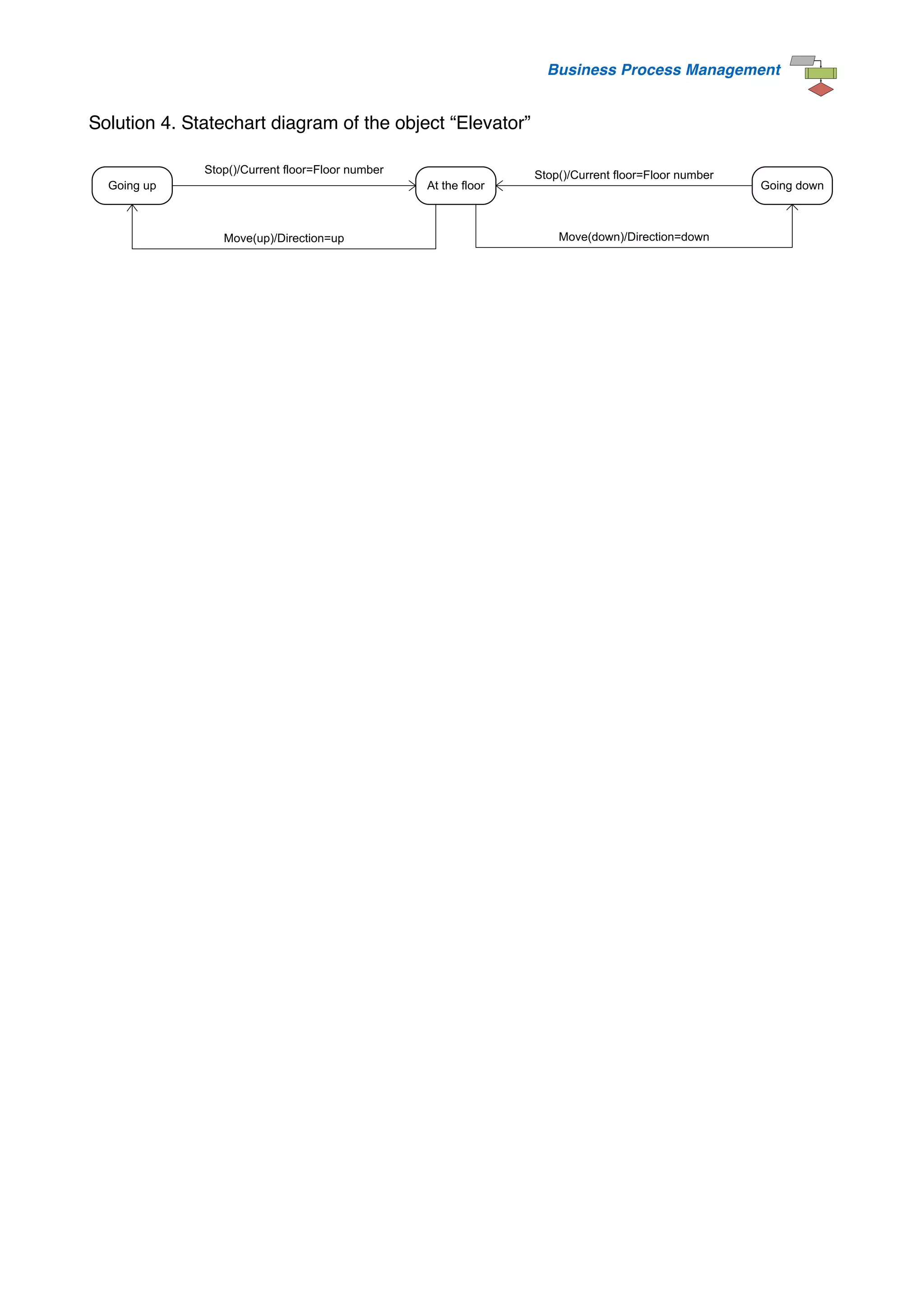
4) A statechart diagram of an elevator with states like "Going up", "Going down", and "At the floor".
![Business Process Management
Solution 3. Activity diagram of the use case “Select Floor”
Elevator Control System
Passenger
Push destination floor button
Close door
Change elevator status(from idle to busy)
Move elevator to destination floor direction
Select destination floor direction (up/down)
Control current floor
Stop elavator at destination floor
Open door at destination floor
Move outside the elavator
Switch external button light off
[<Current floor
NOT=
Destination floor>]
[<Current floor = Destination floor>]
Switch internal button light on](https://image.slidesharecdn.com/elevatorproblem-220808051842-32d90594/75/elevator-problem-pdf-6-2048.jpg)


![Project Management (Practical Qustion Paper) [CBSGS - 75:25 Pattern] {April -...](https://cdn.slidesharecdn.com/ss_thumbnails/pm-cbsgs-apr-2017-pq-190610125500-thumbnail.jpg?width=640&height=640&fit=bounds)