Ch6 v70 sfc_en
•
4 likes•1,621 views

This document provides training materials for configuring sequences with sequential function charts (SFCs) in SIMATIC PCS 7. It includes an overview of SFC structures like linear, parallel, alternative and loop sequences. It also describes how to configure steps, transitions, and sequencers in SFCs as well as how to test SFCs in runtime. An exercise is provided to create an SFC to control temperature setpoints based on process value conditions. Trainees are guided on how to create the SFC layout, configure steps and transitions, compile, download and test the SFC. The document also describes how to open SFCs in test mode based on status combinations.

Recommended
Recommended
More Related Content
What's hot
What's hot (20)
Viewers also liked
Viewers also liked (16)
Similar to Ch6 v70 sfc_en
Similar to Ch6 v70 sfc_en (20)
More from confidencial
More from confidencial (11)
Recently uploaded
Recently uploaded (20)
Ch6 v70 sfc_en
- 1. Training Center for Automation and Drives SIMATIC PCS 7 System Training Configuring with SFCPage 1 Date: 07.12.2006 File:ST-PCS7SYS_V70_sfc.1 SIMATIC PCS 7 Siemens AG 2005. All rights reserved. SITRAIN Training for Automation and Drives Cinfiguring Sequences with SFC Content Page Overview .......................................................................................................................................... 2 Sequence Structures ........................................................................................................................ 3 Action and Transition ........................................................................................................................ 4 Preprocessing and Postprocessing for a Sequencer ......................................................................... 5 Operating State Logic of a Sequencer .............................................................................................. 6 Exercise: Sequence Control - Temperature ..................................................................................... 7 Open SFC (in Test Mode) ................................................................................................................ 9 Sequence Control - Reactor ............................................................................................................. 10 Parameter Control via the SFC ......................................................................................................... 11 Notes ............................................................................................................................................... 12 SFC Operating Mode Logic .............................................................................................................. 13 Run Behavior of an SFC .................................................................................................................. 14 Restart Behavior of the SFC(1) ........................................................................................................ 15 Restart Behavior of the SFC(2) ........................................................................................................ 16 External View of SFC ....................................................................................................................... 17 Exercise: Adding Two Sequencers to the Sequential Control ............................................................ 18 Holding Sequencer with Data Block for Values to be Saved .............................................................. 19 Creating an SFC Type ...................................................................................................................... 20 Creating an SFC Instance ................................................................................................................ 21 Miscellaneous Reference Data ......................................................................................................... 22
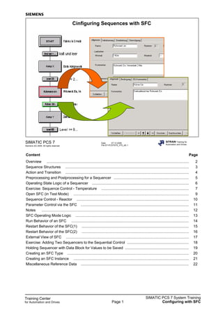
- 2. Training Center for Automation and Drives SIMATIC PCS 7 System Training Configuring with SFCPage 2 Date: 07.12.2006 File:ST-PCS7SYS_V70_sfc.2 SIMATIC PCS 7 Siemens AG 2005. All rights reserved. SITRAIN Training for Automation and Drives Overview Menu bar START END S1 S2 S3 S4 T1 T2 T3 T4 S1 to S4 Steps T1...T4 Transitions Element bar SFC Flow Chart The chart topology, the action functions of the steps, the switching conditions of the transitions and the runtime properties specify the flowchart created with SFC. Editor Graphics are used to structure the flow chart. Connections with block parameters already present in the CFC charts are used to configure the individual components (steps and transitions). Therefore, there is no programming; instead, you just access templates. Insert You can select the structure symbols from the step symbol bar. You click the symbols to insert them (before/after a transition). Steps are always inserted together with the necessary transitions. Step Double click the step symbol to begin configuring the step. You must fill out the tabs for this. When configuring actions, you can use the "Browse…" button to display the blocks contained in the CFC charts ("Magnifying glass") and transfer their parameters to the action list. Transition Double-click the transition symbol to begin configuring the transition. You must fill out the tabs for this. The same things apply to configuring actions as to configuring steps. Runtime Properties The chart will be automatically inserted into the OB where the pointer for the runtime sequence is positioned. Compile/Download Compilation and download are performed in the same way as for CFC. All chart information is maintained in the chart folder. The compilation result is entered in the block folder and downloaded from there to the CPU. Test The sequencer can be run and tested when the CPU is connected and test mode is selected (Test menu). Double-click the step/transition symbol to display the current states.
- 3. Training Center for Automation and Drives SIMATIC PCS 7 System Training Configuring with SFCPage 3 Date: 07.12.2006 File:ST-PCS7SYS_V70_sfc.3 SIMATIC PCS 7 Siemens AG 2005. All rights reserved. SITRAIN Training for Automation and Drives Sequence Structures S1 T12 S2 T23 Linear S21S22 T23 T12 Parallel S2 S3 T12 T13 T24 T34 Alternative S2 T2 T23 Loop S4S3 S3 S1 S1 T12 S1 S2 T2 T23 Jump S3 T12 S1 S3 Linear Sequence Start position: S1 and T12 are active. Step enabling: if T12 is fulfilled, then S1 becomes inactive, and S2 and T23 become active. Parallel Branch Start position: S1 and T12 are active. Step enabling: if T12 is fulfilled, then S1 is inactive, and S21, S22 and T23 become active. Alternative Branch Start position: S1, T12 and T13 are active. Step enabling: 1. If T12 is fulfilled, then S1 is inactive, and S2 and T24 are active (T13, S3, T34 inactive). 2. If T13 is fulfilled, then S1 is inactive, and S3 and T34 are active (T12, S2, T24 inactive). 3. If T12 and T13 are fulfilled, priority to the left is higher; the left branch is active. Loop Start position: S1 and T12 are active. Step enabling: 1. If T12 is fulfilled, then S2 is active, and T23 and T2 are active. 2. If T23 is fulfilled, S2 terminates and S3 is active. 3. If T2 is fulfilled, S2 terminates and is initialized again. 4. If T23 and T2 are fulfilled, then to S3. Jump Start position: S1, T12 and T13 are active. Step enabling: 1. If T12 is fulfilled, then S2 and T23 are active. 2. If T2 is fulfilled, then S3 and its following transition are active. 3. If T12 and T2 are fulfilled, priority to the left is higher; normal sequence (no jump).
- 4. Training Center for Automation and Drives SIMATIC PCS 7 System Training Configuring with SFCPage 4 Date: 07.12.2006 File:ST-PCS7SYS_V70_sfc.4 SIMATIC PCS 7 Siemens AG 2005. All rights reserved. SITRAIN Training for Automation and Drives Action and Transition Step active Transition fulfilled Cycles Cycles Actions Actions that determine what steps must do in the process (such as specify parameters and trigger switching operations) must be configured within the step. You can enter up to 50 actions per step section. Step A step consists of actions that run in three sections: Initialization Initialization is carried out once (for one program run from the OB) when the step becomes active. Processing This section is carried out for every run from the OB until the next transition is fulfilled. If the transition is fulfilled, the terminating section (see below) is carried out during the next OB run of the sequence. Termination This section is carried out once, after the next transition is fulfilled. After the last command, the step becomes inactive and simultaneously, the following step becomes active (with its initialization), depending on the topology. Transitions Transitions contain the step enabling conditions for the next step in the sequence. You can evaluate the validity of up to 16 conditions using five logical gates. If you mouse-click the gate or connecting line, you can convert it to AND, NAND, OR or NOR.
- 5. Training Center for Automation and Drives SIMATIC PCS 7 System Training Configuring with SFCPage 5 Date: 07.12.2006 File:ST-PCS7SYS_V70_sfc.5 SIMATIC PCS 7 Siemens AG 2005. All rights reserved. SITRAIN Training for Automation and Drives Preprocessing and Postprocessing for a Sequencer Possible for each individual sequencer If Blue background = Tab content has been changed SFC Sequencers When created, an SFC chart has a sequencer (called RUN). It can be extended to include other sequencers (which can be inserted, moved or deleted in the chart in the lower bar using the right mouse button). After insertion. the sequencer can be displayed by clicking the associated tab. Start Conditions A logic can be constructed in the sequencer properties same as for with the transition. In this tab, you can define the conditions for the SFC chart/type that are to start the sequencer (e.g. "SFCName.RUN = Active" starts the sequencer if the SFC chart is in "Active" mode). At any one time there is always a maximum of ONE sequencer being processed (active) in an SFC chart. If the start conditions are fulfilled for several sequencers, the "Priority" property decides which sequencer is executed (1 is the lowest and 255 the highest priority). If sequencers with start conditions that are fulfilled at the same time also have the same priority, the sequencer which is located further to the left is initiated first. Preprocessing In this tab, you can define the actions for the SFC chart or type that must be carried out before each sequencer processing call (regardless of whether the respective current step is in initialization, processing or finishing). Each line constitutes one statement. Up to 50 statements are possible in each case. You can change the selection of displayed statements (10) using the vertical scroll bar at the right-hand side. Postprocessing In this tab, you can define the actions for the SFC chart or type that must be carried out after each sequencer processing call. Here, too, up to 50 statements are permitted. The preprocessing and postprocessing tabs are actuated before and after each sequencer cycle, as long as the sequencer is active. Run sequence The recommended rule here is: the SFC is called after the blocks that it queries in the transitions, but before the blocks that it writes with commands (to the extent possible). Remark You will first create an SFC chart with one sequencer. Then, after more information is provided, you will add additional sequencers to the SFC chart.
- 6. Training Center for Automation and Drives SIMATIC PCS 7 System Training Configuring with SFCPage 6 Date: 07.12.2006 File:ST-PCS7SYS_V70_sfc.6 SIMATIC PCS 7 Siemens AG 2005. All rights reserved. SITRAIN Training for Automation and Drives Operating State Logic of a Sequencer Step Control Modes T with Transition T or O with Transition or Operation T and O with Transition and Operation B with Operation T/T and O with step-specific operation Operating mode Operator commands (Online Help Index: operating state logic or OSL) States Following the download operation to the CPU, the sequential control system is in a defined state. This defined state is specified with the SFC Editor (default: Ready). Now the sequential control can begin either automatically (SFC Chart Properties -> Start Options -> Autostart) or after a start command (menu Chart -> Properties -> Start Options -> Operating Parameters). Sequencer Operating State Logic (OSL) Processing of the sequencers is controlled by the sequencer operating state logic. The sequencer's operating state logic is defined in the diagram of the state transitions for sequencer OSL. Operator Commands You can use commands to change the sequential control system between states (e.g. Start, Hold, Resume, Abort, Complete). Step Control Modes The different step control modes modify the behavior of prepared or fulfilled transitions. A change in the step control modes is possible in all of the operating states. The individual step control modes mutually exclude each other. The following step control modes are available: T with Transition T or O with Transition or Operation T and O with Transition and Operation B with Operation T/T and O with step-specific operation
- 7. Training Center for Automation and Drives SIMATIC PCS 7 System Training Configuring with SFCPage 7 Date: 07.12.2006 File:ST-PCS7SYS_V70_sfc.7 SIMATIC PCS 7 Siemens AG 2005. All rights reserved. SITRAIN Training for Automation and Drives Exercise: Sequence Control - Temperature START L<33 SP=70 H>67 SP=50 L<53 SP=30 L<32 END 70 50 30 SP_EXT PV_IN t Step enabling condition: Process value PV_IN less than 33? Step enabling condition: Process value PV_IN greater than 67? Action: Set setpoint SP_EXT to 70 • Linear sequence • Conditions in transitions • Actions in steps • Test Start step Exercise Create a setpoint control for the temperature controller of reactor A (see slide). If specific process values are not reached or are exceeded, the setpoint must be set to defined values. ---------------------------------------------------------------------------------------------------------- Steps 1. Create the SFC chart "SFC_Temp" in the same folder containing the CFC chart for the temperature controller. 2. First create the layout of the sequencer as per the above illustration, with the prescribed names for the steps and transitions. 3. Then configure the steps and transitions. 4. Next, compile ("Changes") and download ("Changes") the program. 5. Test the sequence in test mode. ---------------------------------------------------------------------------------------------------------- Procedure Procedure for configuring the steps: Configure steps Select a step from the sequencer and open it by double-clicking. In the "General" tab, enter the name, min. and max. runtime, the step comment in the control, the step comment in the visualization, and acknowledgment information (if leaving the step has to be acknowledged). The "Initialization", "Processing" and "Termination" tabs must be used to configure the actions in this step. Go to the "Processing" tab, place the cursor in the first free line, and click the "Browse" button (at the bottom of the screen) to look the charts in either the "Plant view" or "Component view" tab until you reach the controller block. Select this block and select the required parameter in the right pane, e.g. The SP_EXT parameter from the CTRL_PID block for the reactor heating control.
- 8. Training Center for Automation and Drives SIMATIC PCS 7 System Training Configuring with SFCPage 8 You now have to assign a value to the selected parameter in your statement (to the right of := ). Enter the temperature value, e.g. 70.0, in accordance with the function of the step. Configure transition Select a transition from the sequencer and open it by double-clicking. In the "General" tab, enter the name, the comment (ES), the OS comment and the acknowledgment information. The "Condition" tab is used to configure individual conditions within the step enabling condition. Here too you can use "Browse" to select the required parameter from the CFC charts and then use the symbols =, <>, =>, =<, >, < to compare it with a specific value or another parameter, e.g. PV_IN from CTRL_PID < 33.0 (degrees) Compile and Download The program is compiled and downloaded (as described in detail in the CFC section) from the SFC chart using the same procedure as for the CFC. Compile and download the changes. The compile and download operation always applies to all CFC and SFC charts in the program to which the SFC chart belongs, i.e. from where you are initiating the procedure (they form a common program). Testing the SFC Test mode is enabled and disabled using the command Debug Test Mode Compared to edit mode, the SFC chart window in test mode is expanded to show an operating and display section at the bottom of the window. In addition to selection of the operating mode (MANUAL, AUTO); you can also see the following buttons for the SFC: - Start - Hold - Resume - Abort - Complete - Stop - Restart - Reset - Error (handling) When the steps and transitions are cycled through, they will display different colors depending on their state: Step active pale green Step held yellow Step contains errors red (e.g. maximum runtime exceeded) Step is inactive but has been processed dark green Step is inactive and has not yet been processed gray Transition fulfilled dark green Transition not fulfilled dark red Transition inactive gray
- 9. Training Center for Automation and Drives SIMATIC PCS 7 System Training Configuring with SFCPage 9 Date: 07.12.2006 File:ST-PCS7SYS_V70_sfc.9 SIMATIC PCS 7 Siemens AG 2005. All rights reserved. SITRAIN Training for Automation and Drives Open SFC (in Test Mode) 1 2 3 5 Menu: Debug Test Mode Debug Open SFCs Select statuses - Multiple selection possible - No selection means no limitation Select the operating mode 4 Find Result 6 Select and open Analyze SFC In test mode it is possible to display SFCs that correspond to a defined combination of statuses. To do this, open any SFC and set it to test mode. Only then is the menu item Debug Open SFCs offered. The required steps are shown in the above slide. Remark The conditions are linked by logical ANDing.
- 10. Training Center for Automation and Drives SIMATIC PCS 7 System Training Configuring with SFCPage 10 Date: 07.12.2006 File:ST-PCS7SYS_V70_sfc.10 SIMATIC PCS 7 Siemens AG 2005. All rights reserved. SITRAIN Training for Automation and Drives Sequence Control - Reactor Go to initial state Reactor C empty and cold Fill first component X to 20% level Cold and empty Level >= 20% Speed monitor for mixer ON Speed monitor for mixer ON Level >= 80% Core temperature to 90 degrees Process temperature reached Settling time 2 min Setpoint tolerance of temperature controller reached Open drain valve, mixer OFF, close temperature controller End initial state Reactor empty and cold Fill second component Y to 80% level End step Exercise The sequence for the manufacturing procedure in Reactor A was described in the "Configuration Overview" tab, page 2. Now implement this sequence using an SFC chart. Configure, compile, download and test this SFC chart. ---------------------------------------------------------------------------------------------------------- Requirement You have implemented and tested the example in the chart "Exer_Reaci" with the MOTOR, VALVE and CTRL_PID blocks. Steps 1. In the plant hierarchy under "ReactorsUnitA", create an SFC chart, "SFC_ReacA". 2. Establish the sequence of the SFC (see picture above). 3. Configure the actions in the individual steps and the signals to be queried in the transitions. 4. Compile and download the program. 5. Test the project. ---------------------------------------------------------------------------------------------------------- Procedure You can derive the sequence from the above picture. Control the filling valves and the drain valve using the VALVE blocks. Control the mixer via the MOTOR block. For the "heating" step, set the controller to AUTOMATIC and the external setpoint to 90°C. You can include waiting times by inserting an empty step (with a minimum runtime setting) and an empty transition.
- 11. Training Center for Automation and Drives SIMATIC PCS 7 System Training Configuring with SFCPage 11 Date: 07.12.2006 File:ST-PCS7SYS_V70_sfc.11 SIMATIC PCS 7 Siemens AG 2005. All rights reserved. SITRAIN Training for Automation and Drives Parameter Control via the SFC Active outputs of the blocks SFC releases the operating mode switchover again (but does not change the operating mode) LIOP_MAN_SEL=0 LIOP_INT_SEL=0 LIOP_SEL=0LIOP_SEL=0Relinquish control of block's operating mode SFC control assumes the control of the blocks (operator cannot operate) LMNQSTARTQCONTROLPass to system SFC control relinquishes control of the blocks (operator can operate again) SP_EXT = (value)AUT_ON (1=on)AUT_OC (1=open)Output commands For controllers onlyLIOP_INT_SEL=1 SPEXON_L=1 Set external setpoint AUT_L=1AUT_L=1AUT_L=1Set Automatic mode SFC determines operating mode (LInk is active, not OPerator) LIOP_MAN_SEL=1LIOP_SEL=1LIOP_SEL=1Assume control of block's operating mode RemarkCTRL_PIDMOTORVALVEBlock Effect Operating Modes For the SFC to be able to pass its commands to the valves or motors via the above listed blocks, it must be able to influence the blocks' operating mode (set the operating mode to AUTOMATIC) and write commands to the suitable inputs. It must also be possible for the plant operator to intervene manually when the control has finished. This means the control must relinquish its control over the blocks again.
- 12. Training Center for Automation and Drives SIMATIC PCS 7 System Training Configuring with SFCPage 12 Date: 07.12.2006 File:ST-PCS7SYS_V70_sfc.12 SIMATIC PCS 7 Siemens AG 2005. All rights reserved. SITRAIN Training for Automation and Drives Notes
- 13. Training Center for Automation and Drives SIMATIC PCS 7 System Training Configuring with SFCPage 13 Date: 07.12.2006 File:ST-PCS7SYS_V70_sfc.13 SIMATIC PCS 7 Siemens AG 2005. All rights reserved. SITRAIN Training for Automation and Drives SFC Operating Mode Logic Buttons for testing the SFC (Online Help Index: operating state logic or OSL) Operating State Logic for SFC State The current operating state of the SFC OSL can be modified by the following events: - Commands (Start, Resume, Hold, etc.) in operating modes "MANUAL" or "AUTO". - External signals (SFC inputs, commands from another SFC, etc.). - Internal signals (commands from custom sequencers, from test mode or SFC visualization). - Implicit state change. Step enable commands Start Trigger start processing Complete Trigger complete processing Hold Trigger hold processing Resume Trigger continue processing, e.g. after an error Error Trigger error processing Abort Trigger cancel processing Stop Trigger stop processing Restart Trigger start processing Reset Change to Ready state
- 14. Training Center for Automation and Drives SIMATIC PCS 7 System Training Configuring with SFCPage 14 Date: 07.12.2006 File:ST-PCS7SYS_V70_sfc.14 SIMATIC PCS 7 Siemens AG 2005. All rights reserved. SITRAIN Training for Automation and Drives Run Behavior of an SFC M Cycleofthe SFC Cycleofthe CFC Interaction with Basic Automation (CFC) The sequential control in the AS is connected to the basic automation via the action and transition functions. A specific runtime behavior is assigned to each SFC. Basic automation using the blocks contained in the CFC charts can have a different runtime behavior than the SFC. You can control an SFC chart using the external view of the SFC chart contained in the CFC chart. The structure of the sequence system makes it possible for the sequential control and the basic automation blocks to run in different cycles, thereby reducing the cyclical load. In the same way, SFCs can be integrated into runtime groups, and can be given a different scan rate or phase offset via these groups. SFC Runtime Options You can set the sequential control behavior in the runtime options. These can be set in the dialog field "SFC Properties Tab: Operating Parameters CPU". Instruction Output On: The actions of active steps will be processed. Off: The actions of active steps will not be processed. Cyclic Execution With "Cyclic Execution: On" the program will automatically revert to "Starting" following the "Completed" operating state. With "Cyclic Execution: Off", the program remains in "Completed" state. Time Monitoring With "Time Monitoring: On", the active time of the step is continuously compared against the monitoring time after the step is activated (object properties for the step, "General" tab, "Maximum Runtime" option), and a step error is reported if the time is exceeded.
- 15. Training Center for Automation and Drives SIMATIC PCS 7 System Training Configuring with SFCPage 15 Date: 07.12.2006 File:ST-PCS7SYS_V70_sfc.15 SIMATIC PCS 7 Siemens AG 2005. All rights reserved. SITRAIN Training for Automation and Drives Restart Behavior of the SFC(1) Restart Behavior With PCS 7 Version 7.0 and higher there is an additional possibility for setting the behavior following a CPU restart (see arrow in slide). In the previous versions, the SFC was always initialized, and the data valid prior to the stop were lost (this is now the default setting). In the new version, the SFC status can be retained. Following a CPU restart, the SFC then retains its status. Using the SFC and process states, the operator can then decide how the SFC is to continue working.
- 16. Training Center for Automation and Drives SIMATIC PCS 7 System Training Configuring with SFCPage 16 Date: 07.12.2006 File:ST-PCS7SYS_V70_sfc.16 SIMATIC PCS 7 Siemens AG 2005. All rights reserved. SITRAIN Training for Automation and Drives Restart Behavior of the SFC(2) ! ? STOP Restart Exercise Set the SFC from the previous exercise such that it retains its state following a CPU restart. Test the restart behavior of the SFC (by means of CPU stop followed by a CPU restart) in the "Component X" and "Heat" step. What happens to the configuration due to this behavior? What happens, for example, with the filling of component X in the reactor in the meantime (between the CPU Stop and Resume command by plant operator, once the CPU is running again)? --------------------------------------------------------------------------------------------------------- Steps 1. Open the SFC, select the menu SFC Properties "Operating parameters CPU" tab and select the "Retain SFC status" option. 2. Compile and download the changes. 3. Switch on test mode, and start the SFC. 4. When the "Component X" step is reached in the SFC, stop the CPU (using PLC Operating Mode Stop). What is output by the output modules to which the valves (simulation) are connected? What does this mean for a real plant? 5. From the last screen form, carry out the CPU restart. You must then decide at some time whether the SFC is to continue or stop/abort. A new command is not output by the SFC up to this point. What commands are output by the valve, motor and controller blocks? Note that the blocks mentioned also exhibit a restart behavior when the CPU is restarted, but they then call their program cyclically in the cyclic interrupt OB with the parameters which they find there.
- 17. Training Center for Automation and Drives SIMATIC PCS 7 System Training Configuring with SFCPage 17 Date: 07.12.2006 File:ST-PCS7SYS_V70_sfc.17 SIMATIC PCS 7 Siemens AG 2005. All rights reserved. SITRAIN Training for Automation and Drives External View of SFC External View The SFC chart has a standard interface through which it can be controlled using CFC interconnections. This interface is represented as a graphic "external view" of the chart. Activate the following menu command in the SFC View External View to open the CFC with an external view window. Representation The external view shows the SFC as a block with an SFC chart symbol in the block header. The block name is the SFC chart name and cannot be changed. Interconnection Inputs can be interconnected to other objects, global addresses or textual interconnections. Please refer to the online help for more information about the individual parameters (Help on SFC External View... See also... Standard interface for SFC charts). There the parameters are listed both alphabetically and according to their use. You cannot add further objects to the CFC chart showing the external view of the SFC. All interconnections must pass over the edge of this chart. Tip Open the external view of the SFC (= a CFC window) and the CFC chart from which the control is to be influenced (= a second CFC window). Arrange both windows side by side. Interconnect the blocks as described in the CFC chapter.
- 18. Training Center for Automation and Drives SIMATIC PCS 7 System Training Configuring with SFCPage 18 Date: 07.12.2006 File:ST-PCS7SYS_V70_sfc.18 SIMATIC PCS 7 Siemens AG 2005. All rights reserved. SITRAIN Training for Automation and Drives Exercise: Adding Two Sequencers to the Sequential Control Start condition RUN sequencer Start condition HOLD sequencer DB SFC_ReacA Save state Safe state Output commands Set operating modes for operation Restore state HOLD! Start condition Resuming sequencer ? ? Exercise Supplement the sequential control for Reactor A as follows: If the plant operator issues a hold command for the SFC control, a second "HOLD sequencer" will start up. This is to ensure that valves V1, V2 and V3 close, the mixer is switched off and the temperature controller is set to manual operation with a preset manual value. The HOLD operating state must not be reached until the two above-mentioned commands have become effective. This state must be saved in a DB. The operator can perform operations in the HOLD state. If the control is to exit the "HOLD" state, the valves, mixer and controller must be switched back to the state saved in the DB, i.e. the state they were in when the HOLD command was issued. This is achieved by using a third "CONTINUE sequencer" which resets the blocks to the desired state and is only exited after a check has been performed. ------------------------------------------------------------------------------------------------------- Steps 1. Insert additional sequencers in the SFC_ReacA. 2. Set the chart properties for the two additional sequencers. 3. Create data block to save data when control is in HOLD state. 4. In SFC_ReacA complete programming of the "HOLD" and "CONTINUE" sequencers. ------------------------------------------------------------------------------------------------------- Procedure 1. Insert two additional sequencers in SFC_ReacA. With the SFC open, go to the "RUN" tab (below), right-click and select Insert Sequence at End to insert another sequencer. One SFC can process up to eight sequencers in alternation. With the SFC open, set the chart properties via Chart Properties Operating Parameters tab as follows: Step Control Mode: T, Operating mode: MANUAL; Instruction Output: checked, Use default operating parameters when SFC chart starts: checked.
- 19. Training Center for Automation and Drives SIMATIC PCS 7 System Training Configuring with SFCPage 19 Date: 07.12.2006 File:ST-PCS7SYS_V70_sfc.19 SIMATIC PCS 7 Siemens AG 2005. All rights reserved. SITRAIN Training for Automation and Drives Holding Sequencer with Data Block for Values to be Saved "Normal" reactor sequencer START (save or restore) END (empty) Checking Create Data Block Create a data block (DB) (e.g., DB1 with a symbolic name, "ReacA_DB"). This block is to be used to save the necessary states when the main sequencer is held (see above for possible structure). To do this, you need to switch to the project component view. Select the block folder, then right-click and select New Object... Data Block to create the global DB1. Enter the symbolic name "ReacA_DB" in the Properties window. Then select the block, right-click and select Open to start the data block editor (see above). Define the necessary parameters in the corresponding data formats. Configuring SFC with Two Additional Sequencers Configure the HOLDING SFC and the RESUMING SFC. HOLDING SFC This is started when a command is received to hold the RUN SFC. "Save" Step In the "Save" step, the relevant pending commands/data are saved in DB1 (see above, content of DB1) and then the desired settings are made. Transition This checks whether the operating modes and values that were set as a precautionary measure have become effective. The sequencer is completed only after the transition is fulfilled. The SFC chart then changes to HOLD state. RESUMING SFC This is started when a command is received to resume the RUN SFC. "Restore" Step The "Restore" step is the opposite to the "Save" step in the HOLDING sequencer, i.e. the data is read from DB1 and distributed across the relevant block parameters/inputs (from right to left). Transition This checks whether the saved states have become effective again before the RUN sequencer resumes activity.
- 20. Training Center for Automation and Drives SIMATIC PCS 7 System Training Configuring with SFCPage 20 Date: 07.12.2006 File:ST-PCS7SYS_V70_sfc.20 SIMATIC PCS 7 Siemens AG 2005. All rights reserved. SITRAIN Training for Automation and Drives Creating an SFC Type Several sequencers possible for one SFC type SFC Type In SFC V6.1 there is an SFC type in addition to the SFC chart. This makes it possible to define sequential controls, including an interface. The runtime logic of the SFC type is based on the interface of the SFC type, i.e. the SFC type cannot access just any process signals. Like function blocks, SFC types must be placed on a CFC chart, where they are given an SFC instance. Creating an SFC Type SFC types cannot be inserted into the plant hierarchy, since they cannot run on their own. Instead, they are created using Insert new object -> SFC type in the component view in the SIMATIC Manager or SFC -> New (select "SFC type" in the "Object type" field) in the SFC editor. Manipulating the SFC Type The SFC type is a manipulable object like the SFC chart; however, it has its own symbol to distinguish it from the latter. The attributes necessary for the SFC type (e.g. S7_m_c) are preset. Seven messages requiring acknowledgement and five that do not require acknowledgement can be configured for each SFC type. The other available messages are required by the SFC type itself. Configuring Using the SFC Type Only the interfaces for the SFC type can be used to configure actions in the steps and the start and step enabling conditions. In other words, external access is via the SFC type interface only.
- 21. Training Center for Automation and Drives SIMATIC PCS 7 System Training Configuring with SFCPage 21 Date: 07.12.2006 File:ST-PCS7SYS_V70_sfc.21 SIMATIC PCS 7 Siemens AG 2005. All rights reserved. SITRAIN Training for Automation and Drives Creating an SFC Instance Operating modes Commands Command enables Lock Control strategy Step control mode Execution option Operating state Operating mode Group display Fault indication Control strategy SFC Instance If an SFC type is used, it is inserted into a CFC chart. An SFC instance will be assigned to it at this point. SFC instances are therefore always assigned to the CFC chart and are addressed via the chart. By assigning the CFC chart to the plant hierarchy, the instances that it contains are also indirectly assigned to the plant hierarchy. Messages SFC instance messages can be configured in the SFC via SFC Message or in the CFC in the object properties dialog box. The messages are PCS-7- compliant and can also be provided with associated values, for instance. Configuration When you configure SFC instances, the interface and the sequencers must not be changed, as they are specified identically for all instances through the SFC type. Changes that are made directly to the instances may be loaded at any time, even if the SFC instance is currently being processed in the automation system. After you have configured any changes, you must use the function OS Compile to ensure that the current data are also available on the OS. Compile If the program is compiled on the ES side, the SFC instances will be compiled along with them. For any given SFC instance, 1+n data blocks will be created (where n = number of sequencers within an SFC).
- 22. Training Center for Automation and Drives SIMATIC PCS 7 System Training Configuring with SFCPage 22 Date: 07.12.2006 File:ST-PCS7SYS_V70_sfc.22 SIMATIC PCS 7 Siemens AG 2005. All rights reserved. SITRAIN Training for Automation and Drives Miscellaneous Reference Data Run Sequence Calling up Reference Data When you have opened a CFC or SFC chart, you can use Options Chart Reference Data... or the symbol in the function bar to display and print the information shown below in list form or in tree structure. You can search for the desired output using the View menu command. Run sequence Graphic representation of the entire run sequence of a CPU. Cross References Chart Element Address A list of all global addresses used in the project, with the elements that have access to them. Cross References SFC Chart Element This displays the existing accesses to the block interfaces in the CFC from any SFC charts. Block interconnections List of all interconnected chart elements. Access in SFC types List of all read and write accesses of the SFC types to their own interface. Cross References Chart Element Runtime Groups Existing accesses from any CFC and SFC charts for all runtime groups. Cross References Block Types The block types used and the locations (CFC chart) where they are used. S7 Resource Allocation The assignment between CFC configuration objects and S7 resources.
- 23. Training Center for Automation and Drives SIMATIC PCS 7 System Training Configuring with SFCPage 23 Local Data All OBs in the program, with the calculated local data requirement and the local data sizes for the individual priority classes as configured offline, and those actually available online. Block Call Hierarchy Graphic representation of the call hierarchy for all blocks in the current program. Textual Interconnections All open textual interconnections are listed. Statistics Number of all objects used by CFC, SRC; S7 resources and the time stamp from the current program, as well as the HMI-relevant block instances for the project. You can use this information to check your configuration structure. For example, you can use the "Cross-References Chart Element Addresses" list to determine which symbols are used and how often, and whether write accesses are synchronized. See the online help for further information. Note The "Reference Data" function is also available in SIMATIC Manager. With PCS 7 projects it is only offered in the context of the chart folder of the CPU.