SlideShare a Scribd company logo
CONNECTING LANS
• To connect LANs, or segments of LANs, we use connecting devices.
Connecting devices can operate in different layers of the Internet model.
Connecting Devices
• It has five different categories based on the layer in which they operate in
a network. The five categories contain devices which can be defined as
1. Those which operate below the physical layer such as a passive hub.
2. Those which operate at the physical layer (a repeater or an active hub).
3. Those which operate at the physical and data link layers (a bridge or a two-
layer switch).
4. Those which operate at the physical, data link, and network layers (a router
or a three-layer switch).
5. Those which can operate at all five layers (a gateway).
15.2
Five categories of connecting devices
1. Passive Hubs
• A passive hub is just a connector. It connects the wires coming from different
branches.
• In a star-topology Ethernet LAN, a passive hub is just a point where the signals
coming from different stations collide; the hub is the collision point.
• This type of a hub is part of the media; its location in the Internet model is below
the physical layer.
2. Repeaters
• A repeater is a device that operates only in the physical layer.
• A repeater receives a signal and, before it becomes too weak or corrupted,
regenerates the original bit pattern. The repeater then sends the refreshed signal.
• A repeater can extend the physical length of a LAN, as shown in Figure.
• A repeater does not actually connect two LANs; it connects two segments of the
same LAN.
• Note that the whole network is still considered one LAN, but the portions of the
network separated by repeaters are called segments.
• It is tempting to compare a repeater to an amplifier, but the comparison is
inaccurate.
• An amplifier cannot discriminate between the intended signal and noise; it
amplifies equally everything fed into it.
• A repeater does not amplify the signal; it regenerates the signal. When it receives
a weakened or corrupted signal, it creates a copy, bit for bit, at the original
strength.
Active Hubs
• An active hub is actually a multipart repeater. It is normally used to create
connections between stations in a physical star topology.
15.5
A repeater connects segments of a LAN.
Note
15.6
A repeater forwards every frame;
it has no filtering capability.
Note
15.7
A repeater is a regenerator,
not an amplifier.
(same signal strength, bit for bit copy)
Note
15.8
Figure 15.3 Function of a repeater
3. Bridges
• The device that can be used to interconnect two separate LANs is known as a bridge.
• It is commonly used to connect two similar or dissimilar LANs as shown in Fig.
• The bridge operates in data-link layer and that is why it is called level-2 relay with reference to the OSI model.
• It links similar or dissimilar LANs, designed to store and forward frames, it is protocol independent and
transparent to the end stations.
Advantages
• higher reliability
• higher performance
• security
• convenience
• Larger geographic coverage.
Key features of a bridge are
• A bridge operates both in physical and data-link layer
• A bridge uses a table for filtering/routing
• A bridge does not change the physical (MAC) addresses in a frame
Types of bridges:
3.1 Transparent Bridges
3.2 Source routing bridges
3.1 Transparent Bridges
• A transparent bridge is a common type of bridge that observes
incoming network traffic to identify media access control (MAC)
addresses.
• It performs two functions:
– bridge forwarding (Forwarding of frames)
– bridge learning(Learning to create the forwarding table)
• If the destination address is present in the forwarding database
already created, the packet is forwarded to the port number to
which the destination host is attached.
• If it is not present, forwarding is done on all parts (flooding). This
process is known as bridge forwarding.
3.1 a) Bridge Forwarding
Basic functions of the bridge
forwarding are mentioned
below:
• Discard the frame if source and
destination addresses are same.
• Forward the frame if the source
and destination addresses are
different and destination
address is present in the table.
• Use flooding if destination
address is not present in the
table.
3.1 b) Bridge Learning
• At the time of installation of a
transparent bridge, the
database, in the form of a
table, is empty.
• As a packet is encountered,
the bridge checks its source
address and build up a table
by associating a source
address with a port address to
which it is connected.
Creation of a bridge-forwarding table
15.15
Figure 15.7 Loop problem in a learning bridge
15.16
Use spanning three in graph theory to avoid loop topology. Spanning tree is a graph
without loop.
Note
Spanning Tree Algorithm
• As redundancy creates loop problem in the system, it is very undesirable.
• To prevent loop problem and proper working of the forwarding and learning processes, there must be only
one path between any pair of bridges and LANs between any two segments in the entire bridged LAN.
• The IEEE specification requires that the bridges use a special topology. Such a topology is known as
spanning tree (a graph where there is no loop) topology.
• The methodology for setting up a spanning tree is known as spanning tree algorithm, which creates a tree out
of a graph.
• Without changing the physical topology, a logical topology is created that overlay on the physical one by
using the following steps:
– Select a bridge as Root-bridge, which has the smallest ID.
– Select Root ports for all the bridges, except for the root bridge, which has least-cost path (say minimum
number of hops) to the root bridge.
– Choose a Designated bridge, which has least-cost path to the Root-bridge, in each LAN.
– Select a port as designated port that gives least-cost path from the designated bridge to the Root
bridge.
– Mark the designated port and the root ports as forwarding ports and the Remaining ones as blocking
ports.
3.2 Source Routing Bridges
• The second approach, known as source routing, where the routing
operation is performed by the source host and the frame
specifies which route the frame is to follow.
• A host can discover a route by sending a discovery frame, which
spreads through the entire network using all possible paths to the
destination as shown in fig.
• Each frame gradually gathers addresses as it goes. The destination
responds to each.
4. Routers
• A router is a three-layer switch (device) that routes packets based on their logical
addresses (host-to-host addressing).
• A router normally connects LANs and WANs in the Internet and has a routing table
that is used for making decisions about the route.
• The routing tables are normally dynamic and are updated using routing protocols.
5.Gateways
• A gateway is normally a computer that operates in all five layers of the
Internet or seven layers of OSI model.
• A gateway takes an application message, reads it, and interprets it. This
means that it can be used as a connecting device between two
internetworks that use different models.
• For example, a network designed to use the OSI model can be connected
to another network using the Internet model.
• Gateways can provide security. Gateway is used to filter unwanted
application-layer messages.
• https://slidetodoc.com/module-5-topic-wired-
lans-by-mukta-desai/

More Related Content

Similar to connecting LANs.pptx

CN 5151(15) Module I part 1.3 21072020.pdf
CN 5151(15) Module I part 1.3 21072020.pdfCN 5151(15) Module I part 1.3 21072020.pdf
CN 5151(15) Module I part 1.3 21072020.pdf
ADARSHN40
 

Similar to connecting LANs.pptx (20)

Network Devices
Network DevicesNetwork Devices
Network Devices
 
Interconnecting devies
Interconnecting deviesInterconnecting devies
Interconnecting devies
 
Lan internetworking devices
Lan internetworking devicesLan internetworking devices
Lan internetworking devices
 
1 networking devices 2014
1 networking devices 20141 networking devices 2014
1 networking devices 2014
 
Networking devices
Networking devicesNetworking devices
Networking devices
 
Network hardware essentials Lec#3
Network hardware essentials Lec#3Network hardware essentials Lec#3
Network hardware essentials Lec#3
 
Networking and Internetworking Devices
Networking and Internetworking DevicesNetworking and Internetworking Devices
Networking and Internetworking Devices
 
Acn Experiment No 2
Acn Experiment No 2Acn Experiment No 2
Acn Experiment No 2
 
Dc ch08 : local area network overview
Dc ch08 : local area network overviewDc ch08 : local area network overview
Dc ch08 : local area network overview
 
Ex-1 Network components.pptx
Ex-1 Network components.pptxEx-1 Network components.pptx
Ex-1 Network components.pptx
 
Computer network_network devices
Computer network_network devicesComputer network_network devices
Computer network_network devices
 
Networking devices
Networking devicesNetworking devices
Networking devices
 
Network hardware.ppt
Network hardware.pptNetwork hardware.ppt
Network hardware.ppt
 
Network devices
Network devicesNetwork devices
Network devices
 
CN 5151(15) Module I part 1.3 21072020.pdf
CN 5151(15) Module I part 1.3 21072020.pdfCN 5151(15) Module I part 1.3 21072020.pdf
CN 5151(15) Module I part 1.3 21072020.pdf
 
Routing.ppt
Routing.pptRouting.ppt
Routing.ppt
 
Bridge
BridgeBridge
Bridge
 
Types of network topology, hub, switch, router, repeater and brouter
Types of network topology, hub, switch, router, repeater and brouterTypes of network topology, hub, switch, router, repeater and brouter
Types of network topology, hub, switch, router, repeater and brouter
 
Introduction to backwards learning algorithm
Introduction to backwards learning algorithmIntroduction to backwards learning algorithm
Introduction to backwards learning algorithm
 
Network Management Devices
Network Management DevicesNetwork Management Devices
Network Management Devices
 

More from Jayaprasanna4

Human computer Interaction ch1-the human.pdf
Human computer Interaction ch1-the human.pdfHuman computer Interaction ch1-the human.pdf
Human computer Interaction ch1-the human.pdf
Jayaprasanna4
 
computer Networks Error Detection and Correction.ppt
computer Networks Error Detection and Correction.pptcomputer Networks Error Detection and Correction.ppt
computer Networks Error Detection and Correction.ppt
Jayaprasanna4
 
HUman computer Interaction Socio-organizational Issues.ppt
HUman computer Interaction Socio-organizational Issues.pptHUman computer Interaction Socio-organizational Issues.ppt
HUman computer Interaction Socio-organizational Issues.ppt
Jayaprasanna4
 
human computer Interaction cognitive models.ppt
human computer Interaction cognitive models.ppthuman computer Interaction cognitive models.ppt
human computer Interaction cognitive models.ppt
Jayaprasanna4
 
World wide web and Hyper Text Markup Language
World wide web and Hyper Text Markup LanguageWorld wide web and Hyper Text Markup Language
World wide web and Hyper Text Markup Language
Jayaprasanna4
 
Lecture 19- Multicasting.ppt
Lecture 19- Multicasting.pptLecture 19- Multicasting.ppt
Lecture 19- Multicasting.ppt
Jayaprasanna4
 

More from Jayaprasanna4 (20)

ethical hacking-mobile hacking methods.ppt
ethical hacking-mobile hacking methods.pptethical hacking-mobile hacking methods.ppt
ethical hacking-mobile hacking methods.ppt
 
ethical hacking in wireless-hacking1.ppt
ethical hacking in wireless-hacking1.pptethical hacking in wireless-hacking1.ppt
ethical hacking in wireless-hacking1.ppt
 
Human computer Interaction ch1-the human.pdf
Human computer Interaction ch1-the human.pdfHuman computer Interaction ch1-the human.pdf
Human computer Interaction ch1-the human.pdf
 
computer Networks Error Detection and Correction.ppt
computer Networks Error Detection and Correction.pptcomputer Networks Error Detection and Correction.ppt
computer Networks Error Detection and Correction.ppt
 
HUman computer Interaction Socio-organizational Issues.ppt
HUman computer Interaction Socio-organizational Issues.pptHUman computer Interaction Socio-organizational Issues.ppt
HUman computer Interaction Socio-organizational Issues.ppt
 
human computer Interaction cognitive models.ppt
human computer Interaction cognitive models.ppthuman computer Interaction cognitive models.ppt
human computer Interaction cognitive models.ppt
 
World wide web and Hyper Text Markup Language
World wide web and Hyper Text Markup LanguageWorld wide web and Hyper Text Markup Language
World wide web and Hyper Text Markup Language
 
CI-Monte-Carlo.ppt
CI-Monte-Carlo.pptCI-Monte-Carlo.ppt
CI-Monte-Carlo.ppt
 
Activity planning.ppt
Activity planning.pptActivity planning.ppt
Activity planning.ppt
 
Cost effort.ppt
Cost effort.pptCost effort.ppt
Cost effort.ppt
 
Activity planning.ppt
Activity planning.pptActivity planning.ppt
Activity planning.ppt
 
unit-1.ppt
unit-1.pptunit-1.ppt
unit-1.ppt
 
BGP.ppt
BGP.pptBGP.ppt
BGP.ppt
 
Lecture 19- Multicasting.ppt
Lecture 19- Multicasting.pptLecture 19- Multicasting.ppt
Lecture 19- Multicasting.ppt
 
line coding.ppt
line coding.pptline coding.ppt
line coding.ppt
 
error detection.ppt
error detection.ppterror detection.ppt
error detection.ppt
 
CS1302 06NOV.pdf
CS1302 06NOV.pdfCS1302 06NOV.pdf
CS1302 06NOV.pdf
 
session and cookies.ppt
session and cookies.pptsession and cookies.ppt
session and cookies.ppt
 
JDBC.ppt
JDBC.pptJDBC.ppt
JDBC.ppt
 
connecting devices.ppt
connecting devices.pptconnecting devices.ppt
connecting devices.ppt
 

Recently uploaded

ONLINE VEHICLE RENTAL SYSTEM PROJECT REPORT.pdf
ONLINE VEHICLE RENTAL SYSTEM PROJECT REPORT.pdfONLINE VEHICLE RENTAL SYSTEM PROJECT REPORT.pdf
ONLINE VEHICLE RENTAL SYSTEM PROJECT REPORT.pdf
Kamal Acharya
 
Digital Signal Processing Lecture notes n.pdf
Digital Signal Processing Lecture notes n.pdfDigital Signal Processing Lecture notes n.pdf
Digital Signal Processing Lecture notes n.pdf
AbrahamGadissa
 
Laundry management system project report.pdf
Laundry management system project report.pdfLaundry management system project report.pdf
Laundry management system project report.pdf
Kamal Acharya
 
School management system project report.pdf
School management system project report.pdfSchool management system project report.pdf
School management system project report.pdf
Kamal Acharya
 
Standard Reomte Control Interface - Neometrix
Standard Reomte Control Interface - NeometrixStandard Reomte Control Interface - Neometrix
Standard Reomte Control Interface - Neometrix
Neometrix_Engineering_Pvt_Ltd
 

Recently uploaded (20)

Introduction to Machine Learning Unit-5 Notes for II-II Mechanical Engineering
Introduction to Machine Learning Unit-5 Notes for II-II Mechanical EngineeringIntroduction to Machine Learning Unit-5 Notes for II-II Mechanical Engineering
Introduction to Machine Learning Unit-5 Notes for II-II Mechanical Engineering
 
KIT-601 Lecture Notes-UNIT-4.pdf Frequent Itemsets and Clustering
KIT-601 Lecture Notes-UNIT-4.pdf Frequent Itemsets and ClusteringKIT-601 Lecture Notes-UNIT-4.pdf Frequent Itemsets and Clustering
KIT-601 Lecture Notes-UNIT-4.pdf Frequent Itemsets and Clustering
 
RESORT MANAGEMENT AND RESERVATION SYSTEM PROJECT REPORT.pdf
RESORT MANAGEMENT AND RESERVATION SYSTEM PROJECT REPORT.pdfRESORT MANAGEMENT AND RESERVATION SYSTEM PROJECT REPORT.pdf
RESORT MANAGEMENT AND RESERVATION SYSTEM PROJECT REPORT.pdf
 
A case study of cinema management system project report..pdf
A case study of cinema management system project report..pdfA case study of cinema management system project report..pdf
A case study of cinema management system project report..pdf
 
KIT-601 Lecture Notes-UNIT-5.pdf Frame Works and Visualization
KIT-601 Lecture Notes-UNIT-5.pdf Frame Works and VisualizationKIT-601 Lecture Notes-UNIT-5.pdf Frame Works and Visualization
KIT-601 Lecture Notes-UNIT-5.pdf Frame Works and Visualization
 
ASME IX(9) 2007 Full Version .pdf
ASME IX(9)  2007 Full Version       .pdfASME IX(9)  2007 Full Version       .pdf
ASME IX(9) 2007 Full Version .pdf
 
ONLINE VEHICLE RENTAL SYSTEM PROJECT REPORT.pdf
ONLINE VEHICLE RENTAL SYSTEM PROJECT REPORT.pdfONLINE VEHICLE RENTAL SYSTEM PROJECT REPORT.pdf
ONLINE VEHICLE RENTAL SYSTEM PROJECT REPORT.pdf
 
Cloud-Computing_CSE311_Computer-Networking CSE GUB BD - Shahidul.pptx
Cloud-Computing_CSE311_Computer-Networking CSE GUB BD - Shahidul.pptxCloud-Computing_CSE311_Computer-Networking CSE GUB BD - Shahidul.pptx
Cloud-Computing_CSE311_Computer-Networking CSE GUB BD - Shahidul.pptx
 
Digital Signal Processing Lecture notes n.pdf
Digital Signal Processing Lecture notes n.pdfDigital Signal Processing Lecture notes n.pdf
Digital Signal Processing Lecture notes n.pdf
 
ENERGY STORAGE DEVICES INTRODUCTION UNIT-I
ENERGY STORAGE DEVICES  INTRODUCTION UNIT-IENERGY STORAGE DEVICES  INTRODUCTION UNIT-I
ENERGY STORAGE DEVICES INTRODUCTION UNIT-I
 
Natalia Rutkowska - BIM School Course in Kraków
Natalia Rutkowska - BIM School Course in KrakówNatalia Rutkowska - BIM School Course in Kraków
Natalia Rutkowska - BIM School Course in Kraków
 
Laundry management system project report.pdf
Laundry management system project report.pdfLaundry management system project report.pdf
Laundry management system project report.pdf
 
Event Management System Vb Net Project Report.pdf
Event Management System Vb Net  Project Report.pdfEvent Management System Vb Net  Project Report.pdf
Event Management System Vb Net Project Report.pdf
 
Quality defects in TMT Bars, Possible causes and Potential Solutions.
Quality defects in TMT Bars, Possible causes and Potential Solutions.Quality defects in TMT Bars, Possible causes and Potential Solutions.
Quality defects in TMT Bars, Possible causes and Potential Solutions.
 
The Benefits and Techniques of Trenchless Pipe Repair.pdf
The Benefits and Techniques of Trenchless Pipe Repair.pdfThe Benefits and Techniques of Trenchless Pipe Repair.pdf
The Benefits and Techniques of Trenchless Pipe Repair.pdf
 
AI for workflow automation Use cases applications benefits and development.pdf
AI for workflow automation Use cases applications benefits and development.pdfAI for workflow automation Use cases applications benefits and development.pdf
AI for workflow automation Use cases applications benefits and development.pdf
 
KIT-601 Lecture Notes-UNIT-3.pdf Mining Data Stream
KIT-601 Lecture Notes-UNIT-3.pdf Mining Data StreamKIT-601 Lecture Notes-UNIT-3.pdf Mining Data Stream
KIT-601 Lecture Notes-UNIT-3.pdf Mining Data Stream
 
School management system project report.pdf
School management system project report.pdfSchool management system project report.pdf
School management system project report.pdf
 
Standard Reomte Control Interface - Neometrix
Standard Reomte Control Interface - NeometrixStandard Reomte Control Interface - Neometrix
Standard Reomte Control Interface - Neometrix
 
Pharmacy management system project report..pdf
Pharmacy management system project report..pdfPharmacy management system project report..pdf
Pharmacy management system project report..pdf
 

connecting LANs.pptx

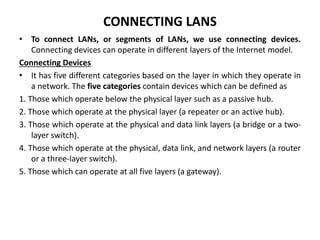
  • 1. CONNECTING LANS • To connect LANs, or segments of LANs, we use connecting devices. Connecting devices can operate in different layers of the Internet model. Connecting Devices • It has five different categories based on the layer in which they operate in a network. The five categories contain devices which can be defined as 1. Those which operate below the physical layer such as a passive hub. 2. Those which operate at the physical layer (a repeater or an active hub). 3. Those which operate at the physical and data link layers (a bridge or a two- layer switch). 4. Those which operate at the physical, data link, and network layers (a router or a three-layer switch). 5. Those which can operate at all five layers (a gateway).
  • 2. 15.2 Five categories of connecting devices
  • 3. 1. Passive Hubs • A passive hub is just a connector. It connects the wires coming from different branches. • In a star-topology Ethernet LAN, a passive hub is just a point where the signals coming from different stations collide; the hub is the collision point. • This type of a hub is part of the media; its location in the Internet model is below the physical layer. 2. Repeaters • A repeater is a device that operates only in the physical layer. • A repeater receives a signal and, before it becomes too weak or corrupted, regenerates the original bit pattern. The repeater then sends the refreshed signal. • A repeater can extend the physical length of a LAN, as shown in Figure.
  • 4. • A repeater does not actually connect two LANs; it connects two segments of the same LAN. • Note that the whole network is still considered one LAN, but the portions of the network separated by repeaters are called segments. • It is tempting to compare a repeater to an amplifier, but the comparison is inaccurate. • An amplifier cannot discriminate between the intended signal and noise; it amplifies equally everything fed into it. • A repeater does not amplify the signal; it regenerates the signal. When it receives a weakened or corrupted signal, it creates a copy, bit for bit, at the original strength. Active Hubs • An active hub is actually a multipart repeater. It is normally used to create connections between stations in a physical star topology.
  • 5. 15.5 A repeater connects segments of a LAN. Note
  • 6. 15.6 A repeater forwards every frame; it has no filtering capability. Note
  • 7. 15.7 A repeater is a regenerator, not an amplifier. (same signal strength, bit for bit copy) Note
  • 9. 3. Bridges • The device that can be used to interconnect two separate LANs is known as a bridge. • It is commonly used to connect two similar or dissimilar LANs as shown in Fig. • The bridge operates in data-link layer and that is why it is called level-2 relay with reference to the OSI model. • It links similar or dissimilar LANs, designed to store and forward frames, it is protocol independent and transparent to the end stations. Advantages • higher reliability • higher performance • security • convenience • Larger geographic coverage. Key features of a bridge are • A bridge operates both in physical and data-link layer • A bridge uses a table for filtering/routing • A bridge does not change the physical (MAC) addresses in a frame Types of bridges: 3.1 Transparent Bridges 3.2 Source routing bridges
  • 10.
  • 11. 3.1 Transparent Bridges • A transparent bridge is a common type of bridge that observes incoming network traffic to identify media access control (MAC) addresses. • It performs two functions: – bridge forwarding (Forwarding of frames) – bridge learning(Learning to create the forwarding table) • If the destination address is present in the forwarding database already created, the packet is forwarded to the port number to which the destination host is attached. • If it is not present, forwarding is done on all parts (flooding). This process is known as bridge forwarding.
  • 12. 3.1 a) Bridge Forwarding Basic functions of the bridge forwarding are mentioned below: • Discard the frame if source and destination addresses are same. • Forward the frame if the source and destination addresses are different and destination address is present in the table. • Use flooding if destination address is not present in the table.
  • 13. 3.1 b) Bridge Learning • At the time of installation of a transparent bridge, the database, in the form of a table, is empty. • As a packet is encountered, the bridge checks its source address and build up a table by associating a source address with a port address to which it is connected.
  • 14. Creation of a bridge-forwarding table
  • 15. 15.15 Figure 15.7 Loop problem in a learning bridge
  • 16. 15.16 Use spanning three in graph theory to avoid loop topology. Spanning tree is a graph without loop. Note
  • 17. Spanning Tree Algorithm • As redundancy creates loop problem in the system, it is very undesirable. • To prevent loop problem and proper working of the forwarding and learning processes, there must be only one path between any pair of bridges and LANs between any two segments in the entire bridged LAN. • The IEEE specification requires that the bridges use a special topology. Such a topology is known as spanning tree (a graph where there is no loop) topology. • The methodology for setting up a spanning tree is known as spanning tree algorithm, which creates a tree out of a graph. • Without changing the physical topology, a logical topology is created that overlay on the physical one by using the following steps: – Select a bridge as Root-bridge, which has the smallest ID. – Select Root ports for all the bridges, except for the root bridge, which has least-cost path (say minimum number of hops) to the root bridge. – Choose a Designated bridge, which has least-cost path to the Root-bridge, in each LAN. – Select a port as designated port that gives least-cost path from the designated bridge to the Root bridge. – Mark the designated port and the root ports as forwarding ports and the Remaining ones as blocking ports.
  • 18. 3.2 Source Routing Bridges • The second approach, known as source routing, where the routing operation is performed by the source host and the frame specifies which route the frame is to follow. • A host can discover a route by sending a discovery frame, which spreads through the entire network using all possible paths to the destination as shown in fig. • Each frame gradually gathers addresses as it goes. The destination responds to each.
  • 19. 4. Routers • A router is a three-layer switch (device) that routes packets based on their logical addresses (host-to-host addressing). • A router normally connects LANs and WANs in the Internet and has a routing table that is used for making decisions about the route. • The routing tables are normally dynamic and are updated using routing protocols.
  • 20. 5.Gateways • A gateway is normally a computer that operates in all five layers of the Internet or seven layers of OSI model. • A gateway takes an application message, reads it, and interprets it. This means that it can be used as a connecting device between two internetworks that use different models. • For example, a network designed to use the OSI model can be connected to another network using the Internet model. • Gateways can provide security. Gateway is used to filter unwanted application-layer messages.
  • 21.