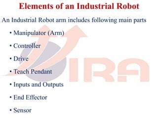
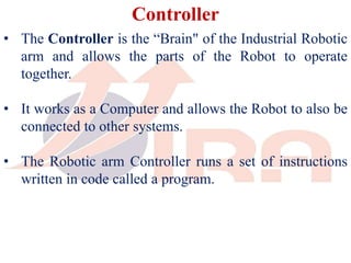
An industrial robot arm consists of several main parts including a manipulator, controller, drive, teach pendant, inputs/outputs, end effector, and sensors. The controller acts as the robot's brain and allows the parts to operate together. It can be programmed using code to perform tasks. Drives powered by hydraulics, electricity, or pneumatics move the manipulator's links. The end effector interacts directly with materials and can be changed. Sensors provide feedback to the controller about the robot's environment.


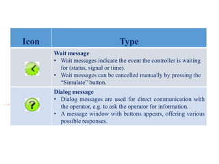


![Inline form “PTP” (Motion)
Item Description
1 Motion type PTP
2 • The name of the end point is issued automatically, but can be
overwritten as required.
• To edit the point data, touch the arrow; the option window Frames
opens.
3 CONT: end point is approximated.
[Empty box]: the motion stops exactly at the end point.
4 Velocity
• PTP motions: 1 … 100%
5 Motion data set:
• Acceleration
• Approximation distance (if CONT is entered in box (3))](https://image.slidesharecdn.com/virabasicsofrobotlevel1-230401093756-07957ab0/85/VIRA_Basics_of_Robot_Level_1-pptx-29-320.jpg)
![Inline form “LIN” (Motion)
Item Description
1 Motion type LIN
2 • The name of the end point is issued automatically, but can be
overwritten as required.
• To edit the point data, touch the arrow; the option window Frames
opens.
3 CONT: end point is approximated.
[Empty box]: the motion stops exactly at the end point.
4 Velocity
• LIN motions: 1 … 100 m/s
5 Motion data set:
• Acceleration
• Approximation distance (if CONT is entered in box (3))](https://image.slidesharecdn.com/virabasicsofrobotlevel1-230401093756-07957ab0/85/VIRA_Basics_of_Robot_Level_1-pptx-30-320.jpg)
![Inline form “CIRC” (Motion)
Item Description
1 Motion type CIRC
2 • The name of the end point is issued automatically, but can be
overwritten as required.
• To edit the point data, touch the arrow; the option window Frames
opens.
3 CONT: end point is approximated.
[Empty box]: the motion stops exactly at the end point.
4 Velocity
• CIRC motions: 1 … 100 m/s
5 Motion data set:
• Acceleration
• Approximation distance (if CONT is entered in box (3))](https://image.slidesharecdn.com/virabasicsofrobotlevel1-230401093756-07957ab0/85/VIRA_Basics_of_Robot_Level_1-pptx-31-320.jpg)


