Download to read offline
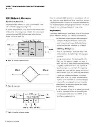
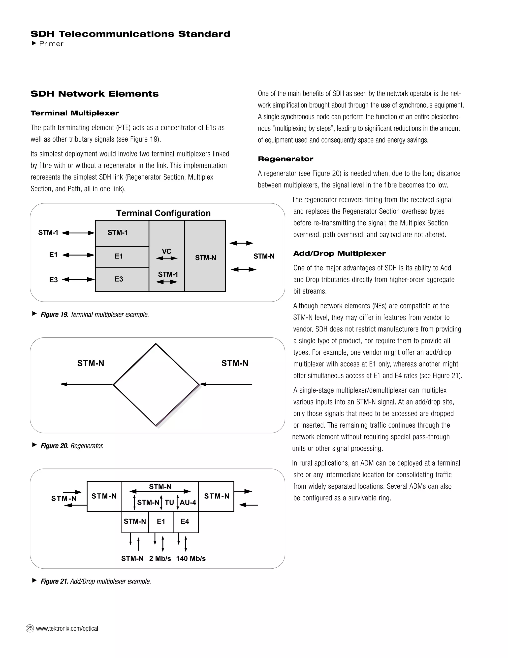

The document discusses various network elements in SDH networks, including terminal multiplexers, regenerators, add/drop multiplexers, cross-connects, and flexible multiplexers. Terminal multiplexers act as concentrators and their simplest deployment involves two linked by fiber. Regenerators are needed when signal levels become too low over long distances. Add/drop multiplexers allow tributaries to be added and dropped directly from higher order bit streams. Cross-connects accept various SDH rates and access payloads to interconnect STM-1 signals. Flexible multiplexers act as a concentration system before services are distributed locally. Common network configurations include point-to-point and point-to-multipoint using add