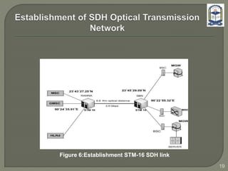
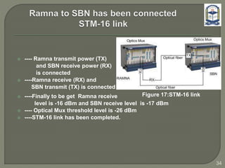
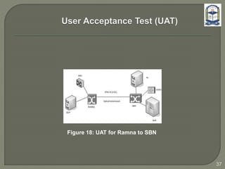
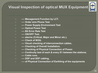
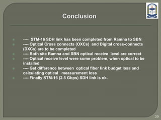
The document discusses the installation and configuration of an STM-16 synchronous digital hierarchy (SDH) transmission link between Ramna and SBN sites. Key steps included installing single-mode fiber, optical multiplexer equipment, electrical interfaces and cross-connects. Testing validated the optical power levels, fiber continuity and service commissioning over the 2.5 Gbps link. Minor issues were addressed during installation and the STM-16 SDH connection was completed successfully.
SDH (Synchronous Digital Hierarchy) & Its Architectureijsrd.com
The SDH (Synchronous Digital Hierarchy) tell us about transferring large amount of data over an same optical fiber and this document gives us the information about the structure and architecture of SDH.
Generalized Multi-Protocol Label Switching (GMPLS) is a protocol suite extending MPLS to manage
further classes of interfaces and switching technologies other than packet interfaces and switching, such
as time division multiplexing, layer-2 switching, wavelength switching and fiber-switching.
GMPLS (Generalized Multiprotocol Label Switching), also known as Multiprotocol Lambda Switching. In
particular, GMPLS will provide support for photonic networking, also known as optical communications.
TRANSMISSION :
A PROCESS WHERE TRAFFIC (VOICE,DATA,VIDEO) IS DESPATCHED OVER A MEDIUM BETWEEN THE SOURCE AND THE DESTINATION
TYPES OF TRANSMISSION MEDIA :
WIRED TRANSMISSION MEDIA
1.COPPER CABLE
2.OPTICAL FIBER
WIRELESS TRANSMISSION MEDIA
1.VSAT NETWORKS
2.MICROWAVE RADIO
Welcome to Issue 13 in which we continue our Journey with Daaji exploring consciousness. This time he takes to the space-time continuum and the creation of the universe from a yogic perspective. Dr. James Doty highlights the role of compassion in our lives and Luke Coutinho and Samara Mahindra share a holistic medical approach to cancer recovery. We also showcase a successful business model on the yogic principles of Yama, learn more about the basic laws of the universe, and go for a spectacular journey of Buddhism in Myanmar. www.heartfulnessmagazine.com
CUENTA CON ALGUNAS DIAPOSITIVAS DEL RECORRIDO TURISTICO POR EL PUEBLO DE TEQUILA JALISCO CON LOS GRUPOS DE ALIMENTOS Y REFRIGERACION DEL TRAYECTO BIOLOGICO.
Here are results from surveying all my clients from last year. I'm so grateful to have gotten to know so many talented, hard-working and smart individuals! I'm proud of the results and the 98% response rate. Thank you!
Transmission system used for optical fibers Jay Baria
In this presentation I have explained various types of transmission system used for optical transmission and also described about the budget method that has to be followed while selecting an source for optical fibers and also about the factors that should be consider while selecting an source.
10Gb/s Tunable SFP+ Transceiver Hot Pluggable, Duplex LC, +3.3V, 100GHz, Mono...Allen He
SHPP-10G-Tun tunable SFP+ Optical Transceiver provides a high-speed serial link at 9.95 to 11.3 Gbps data rates. It
complies with SFP+ Multi-Source Agreement (MSA) Specification. It provides Digital diagnostics functions via a 2-wire serial
interface as specified in SFF-8472. It fulfills the tunable via the monolithically Mach-Zehnder Modulators (MZM) laser. It support optical link up to 80km for SONET/SDH, 10G FC and Ethernet applications.
3. Transmission network consist of the following major transmission
technologies:
Optical fiber communication link
Microwave communication link
3
Transmission Network link
4. 4
Transmission Protocol
SDH (Synchronous Digital Hierarchy)
PDH ( Plesiochronus Digital Hierarchy)
Both optical fiber and microwave communication
link support PDH and SDH link
6. ---- It stands for Synchronous Digital Hierarchy
---- It is a transmission protocol
---- It defines frame structure, multiplexing method, digital rates
hierarchy and interface code pattern
---- It needs for a system to process increasing amounts of information
---- It is a new standard that allows mixing equipment from different
suppliers
6
8. Overview of PDH ( Plesiochronus
Digital Hierarchy) Transmission
Network
8
9. ---- It stands for Plesiochronus Digital Hierarchy
---- It is a transmission protocol
---- It is a technology used in networks run in a state where different
parts of the network are nearly, but not quite perfectly, synchronized
----- It allows transmission of data streams that are nominally running
at the same rate, but allowing some variation on the speed around a
nominal rate
9
10. Signal Bit rate Channel
E1 2.048 Mbps 30-31
E2 8.448 Mbps 120-124
E3 34.368 Mbps 480-496
E4 139.264 Mbps 1920-1984
Channel capacity of PDH
10
11. Advantages of SDH over PDH
PDH
Electrical interfaces
--- Only regional standards.
PDH rate hierarchies for PDH:
European (2.048 Mb/s),
Japanese, North American (1.544
Mb/s).
Optical interfaces
--- No standards for optical line
equipments, manufacturers
develop at their will.
SDH
Electrical interfaces
--- Can be connected with
existing PDH signals.
Optical interfaces
--- Can be connected to multiple
vendors’ optical transmission
equipments. 11
12. PDH
• Weak Operation,
Administration &
Maintenance function.
12
SDH
• Abundant overheads
bytes for operation,
administration and
maintenance
• About 5% of the total
bytes are being used
13. Low rate SDH to higher rate SDH
( STM-1→STM-4→STM-16→STM-64 )
4:1
STM-1
A
STM-1
B
STM-1
C
STM-1
D
A
B
D
C
B
A
D
C
B
A
…
STM-4
One Byte from
STM-1 B
13
Figure 1:SDH Multiplexing
14. 14
PDH : Asynchronous Multiplexing
The location of low-rate signals in high-rate signals is neither regular nor
predictable
Not suitable for huge-volume transmission
140 Mb/s
34 Mb/s 34 Mb/s
8 Mb/s 8 Mb/s
2 Mb/s
140 Mb/s
de-multiplexer
de-multiplexer
de-multiplexer multiplexer
multiplexer
multiplexer
level by level
Figure 2: PDH Multiplexing
15. Communication System Overview
Message
Source
Transmitter Transmission
Medium/Channel
Receiver
Message
Destination
Noise,
Interference,
Distortion
Information Capacity, C = B log2 (1+SNR)
Development trend: Increase the bandwidth
Move to higher frequency
Figure 3: Basic concept of transmission system
15
16. 16
Indoor unit Indoor unit
STM-1
Optical Mux
STM-1
Optical Mux
63 E1
Add drop
Multiplexing
Add drop
Multiplexing
63 E1
Outdoor unit Outdoor unit
Out door unit
Out door unit
Point to Point
communication
Point to Point
communication
IF cableIF Cable
Wave guide
Wave guide
Figure 4: P to P SDH MW link
17. SDH Optical Communication link
Optical Communication: Deals with theory and applications of
light wave signals (of frequencies ~1014 Hz or STM-256)
Optical Communication:
Uses light as a
medium of
communication
Optoelectronics:
Deals with other
applications of light
17
18. Overview of Optical Communication
Light Source: LASER or LED
Digital
Signal
Light
Source &
Modulator
Photo-
detector
Digital
Signal
Optical Fiber
Optical Fiber: one or more glass fibers, and optoelectronic
repeater or fiber amplifier
Detector: APD or PIN
Figure 5: Optical communication
18
20. ---- To be newly connection Ramna to SBN for GMSC, MSC,, BSC,
MGW etc. HLR
---- It is requirements STM-16 (2.5 Gbps) SDH link.
---- For STM-16 link the only physical media is suitable is Single mode
optical fiber cable. Hence Single Mode G.652 fiber is selected between
those sites and has been installed
20
21. ---- Synchronous digital hierarchy (SDH) refer to a group of fiber-
optic transmission rates that can transport digital signals with
different capacities.
---- STM-16 SDH Multiplexer is cost-effective and compact STM-16
SDH multiplexer equipment designed to manage and derive
services from the optical core to access
---- Microwave SDH link does not support STM-16 (2.5 Gbps).
21
23. Just take the difference between transmitter power and receiver
sensitivity
Example:
Tx =-20 dB Rx = -30 dB
Link Margin = 10 dB
The loss of the total cable system must not exceed the Link Margin
23
24. Typical Attenuation for Single mode fiber:
0.4 dB/km @ 1310 nm
Typical Attenuation for connector
0.5 dB/connector @ 1310 nm
Typical Attenuation for Splice
0.3 dB/Splice @ 1310 nm
24
25. SM @1310 nm; typical values
6 km length x 0.4 dB/km = 2.4 dB
4 connector pairs x 0.5 dB = 2.0 dB
4 splice (mechanical) x 0.3 dB = 1.2 dB
___________________________________________________
Total = 5.6 dB
Transmitter Receiver
Connector
Splice
Connector
25
27. ----Optical mux installation inside the cabinet.
---- Insert the optical interfaces
(STM-16 S16.1 card) on the optics rack.
---- Insert the Processing interface (PQ1 card)
---- Insert the Tributary interface (D75S card)
----- Optical Cross-connects (OXCs)
processing board CXL16
-----Digital Cross-connects (DXCs) board GXCSA
Figure 9: Optics 2500
27
28. --- Installing Insulation ODF rack
----Verities type of optical connector.
These are SC-FC , FC-FC, and LC-FC etc
optical I-connector/Adapter
---- Different types patch cord use in optical
fiber for termination ODF to optical equipment
----Optical patch cord connect between
ODF and Optical interfaces board.
Figure 10:ODF
28
29. ---- The trunk cables include 75Ω/120Ω E1
cables
--- Electrical interface to connect
optical interfaces.
---- 63 E1 Digital distribution frame (DDF).
---- Coaxial cable connect between DDF and
Electrical interface.
Figure 11:DDF
29
30. ---- The labels are affixed to the DC cables
that provide power for the cabinets
---- the protection grounding cables, including
the –48V, PGND, and BGND cables
--- The labels for DC power cables are affixed
to one side of the identification plates on cable ties
Figure 12:DC Power
(1) (2)
TO:
A01 -48V2
B08
TO:
B03 -48V2
30
31. ---- Splicing is the act of joining two optical
fibers end-to-end using heat
---- Termination between two optical adapter
--- Each Splice loss 0.5 dBm
Figure 13:Splice Machine
31
32. ---- Optical fiber measurement equipment is
Time Domain Reflecto meter (OTDR)
---- Get actual optical fiber length 6.8 Km
from OTDR
6.8 Km length x -0.4 dBm/km = -2.72 dBm
4 connector pairs x -0.5 dBm = -2.0 dBm
6 splice (mechanical) x -0.4 dBm = -2.4 dBm
__________________________________________
Total = -7.12 dBm
Figure 14:OTDR
Figure 15:Optical power
measure
32
33. ---- Optical cross-connects (OXCs) CXL16
transmit power is -2 dBm
---- Get optical power meter receive -2.1 dBm ,
wave length 1310nm
---- When fiber through interface from Ramna
to SBN receive level is -12 dBm ,
wave length 1310 nm.
---- Ramna and SBN almost same receive level.
Figure 16:Interface power
measurement
33
34. ---- Ramna transmit power (TX)
and SBN receive power (RX)
is connected
----Ramna receive (RX) and
SBN transmit (TX) is connected
----Finally to be get Ramna receive
level is -16 dBm and SBN receive level is -17 dBm
---- Optical Mux threshold level is -26 dBm
----STM-16 link has been completed.
Figure 17:STM-16 link
34
35. ---- Starting the PC
---- Setting IP Address for a PC
---- Starting the T2000-LCT Server
---- Network Element Commissioning
---- Configuring NE Commissioning Data
---- Configuration NE name, Date and Time
---- Configuration Services to the NE for Commissioning
35
36. ---- Testing Fiber Connection
---- Testing connection of Cables to interfaces
---- Testing Optical Fiber Jumper Connection
---- Testing Specifications of Optical Interfaces
---- Testing Received Optical power of an optical interface Board
36
38. ---- Management Function by LCT.
---- Order wire Phone Test
---- Power Supply Environment Test
---- Optical Power Test
---- Bit Error Rate Test
---- ON/OFF Test.
---- alarms (Critical, Major and Minor etc.).
---- Check of BOQ.
---- Visual checking of interconnection cables.
---- Checking of Overall Installation.
---- Checking of Physical Connection of Power.
---- Continuity test of each & every E1 between the stations.
---- Cable runs.
---- DDF and DDF cabling.
---- of Physical Connection of Earthling of the equipments
38
39. ---- STM-16 SDH link has been completed from Ramna to SBN
---- Optical Cross connects (OXCs) and Digital cross-connects
(DXCs) are to be completed
---- Both site Ramna and SBN optical receive level are correct
---- Optical receive level were some problem, when optical to be
installed
---- Get difference between optical fiber link budget loss and
calculating optical measurement loss
---- Finally STM-16 (2.5 Gbps) SDH link is ok.
39