Download to read offline
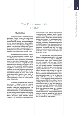
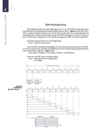
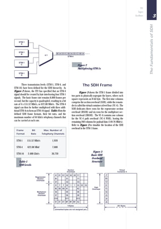

Global changes and increased competition forced telecommunications providers to improve efficiency. The existing analog transmission systems were replaced by digital networks using Plesiochronous Digital Hierarchy (PDH), which had some limitations. The Synchronous Digital Hierarchy (SDH) standard was developed to address these limitations by defining optical interfaces, dynamic payload management, and integration of new services. SDH multiplexes lower speed signals into a Synchronous Transport Module at different levels up to STM-16 to efficiently transmit digital signals over long distances.