Download as PDF, PPTX

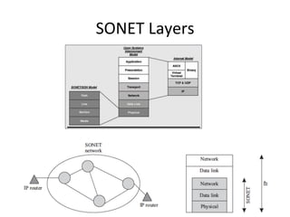
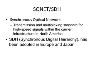
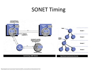
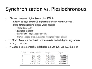
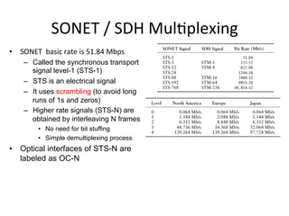
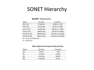

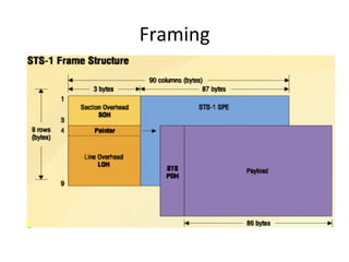
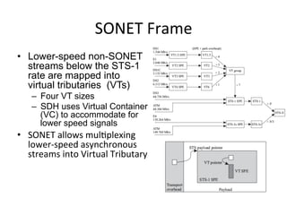
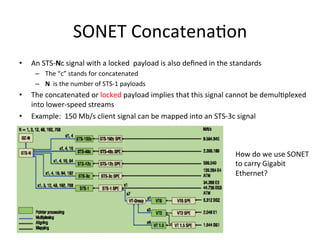
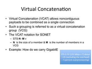
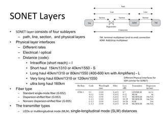
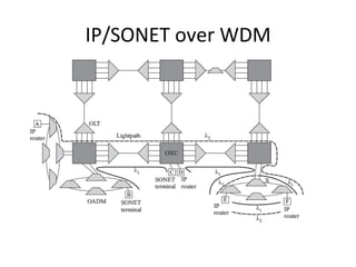
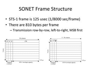
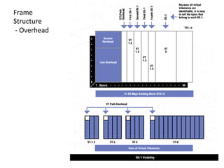
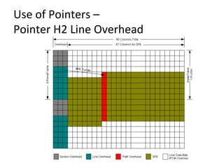
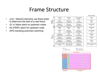
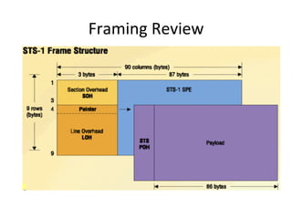
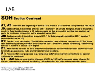
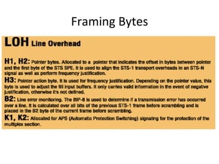

SONET/SDH is a standard developed for optical networks to transport telecommunication signals over optical fiber with synchronous timing. It uses synchronous transport signals and time division multiplexing to combine lower rate connections. SONET frames contain overhead bytes for management and a synchronous payload envelope containing client data. Higher rates are obtained by interleaving multiple lower rate frames. SONET provides advantages over older asynchronous standards through integral rate hierarchies and extensive performance monitoring capabilities.


