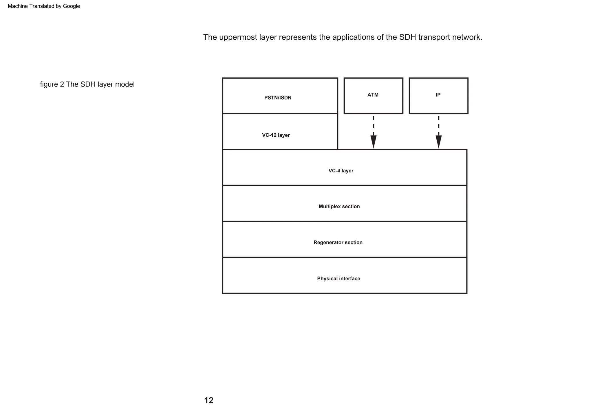
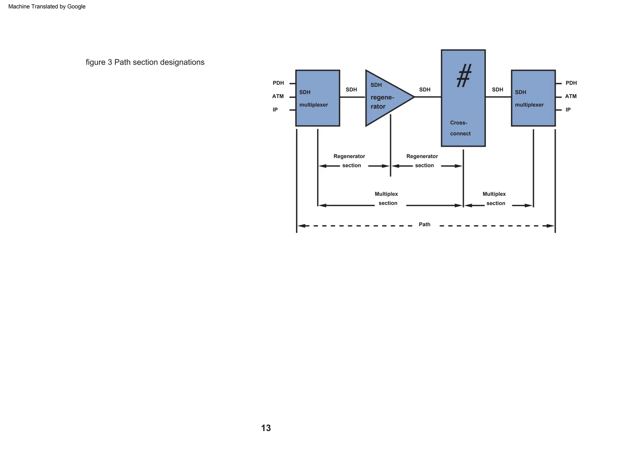
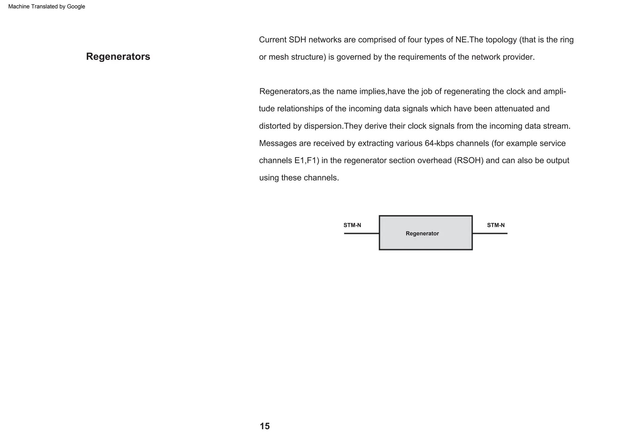
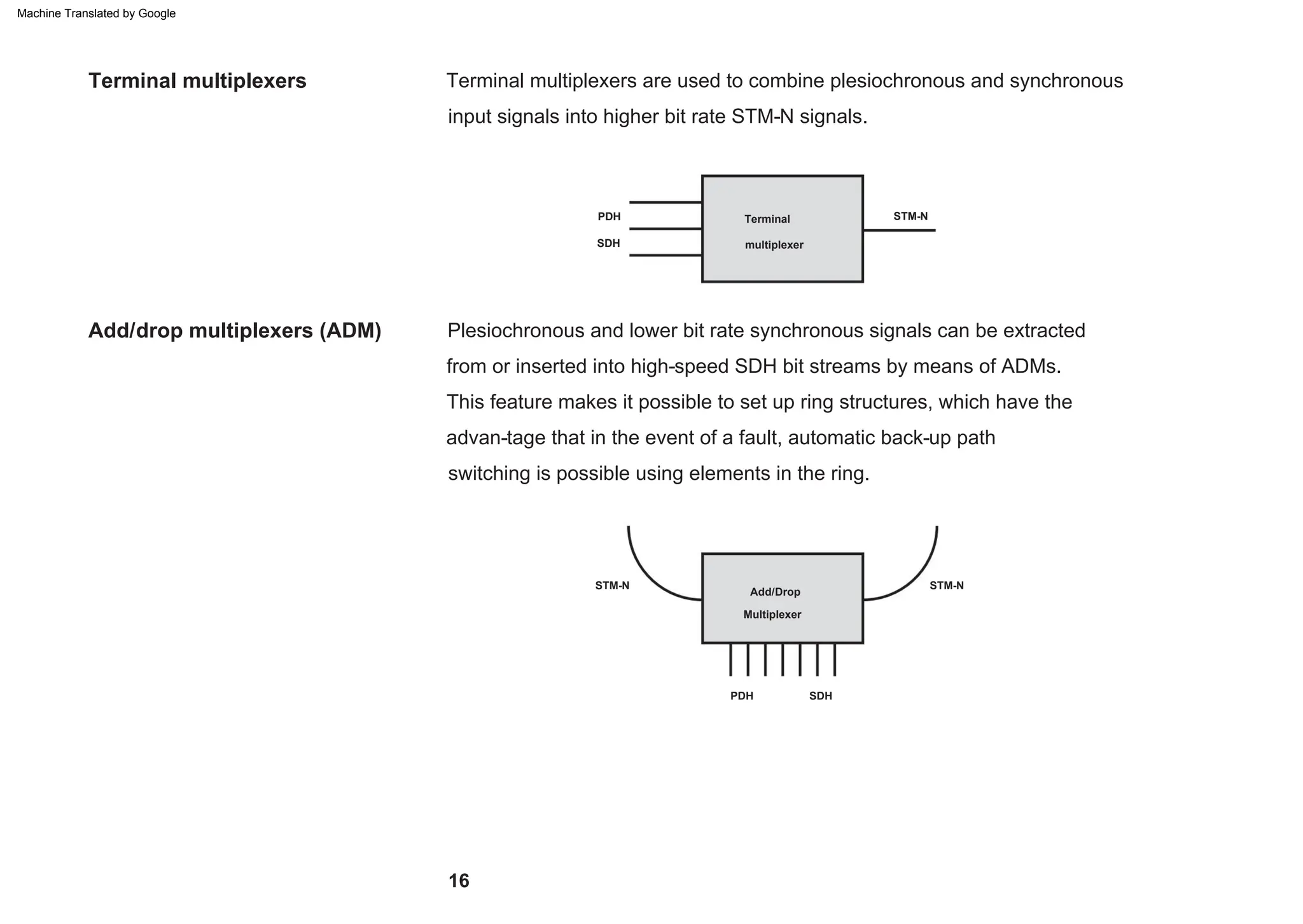
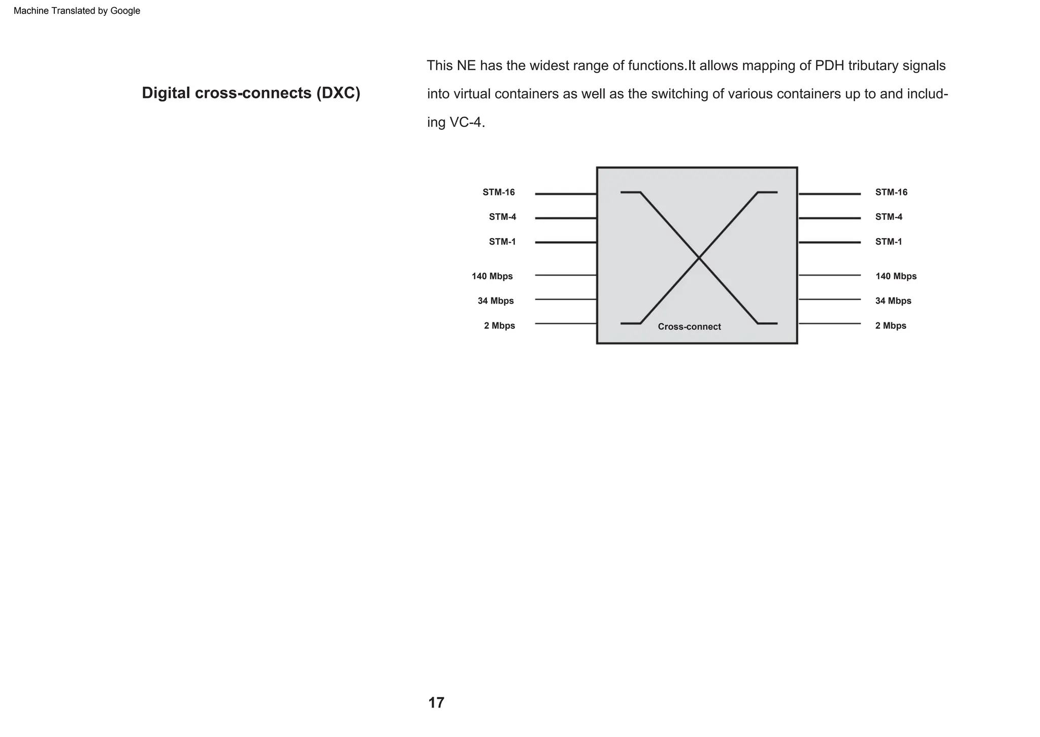
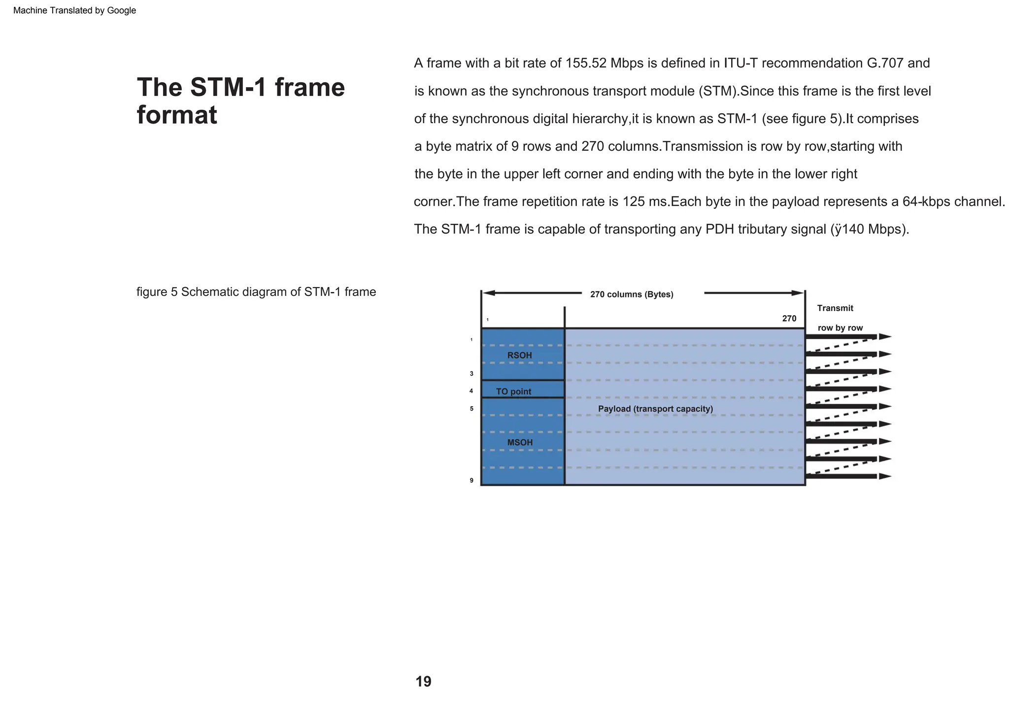
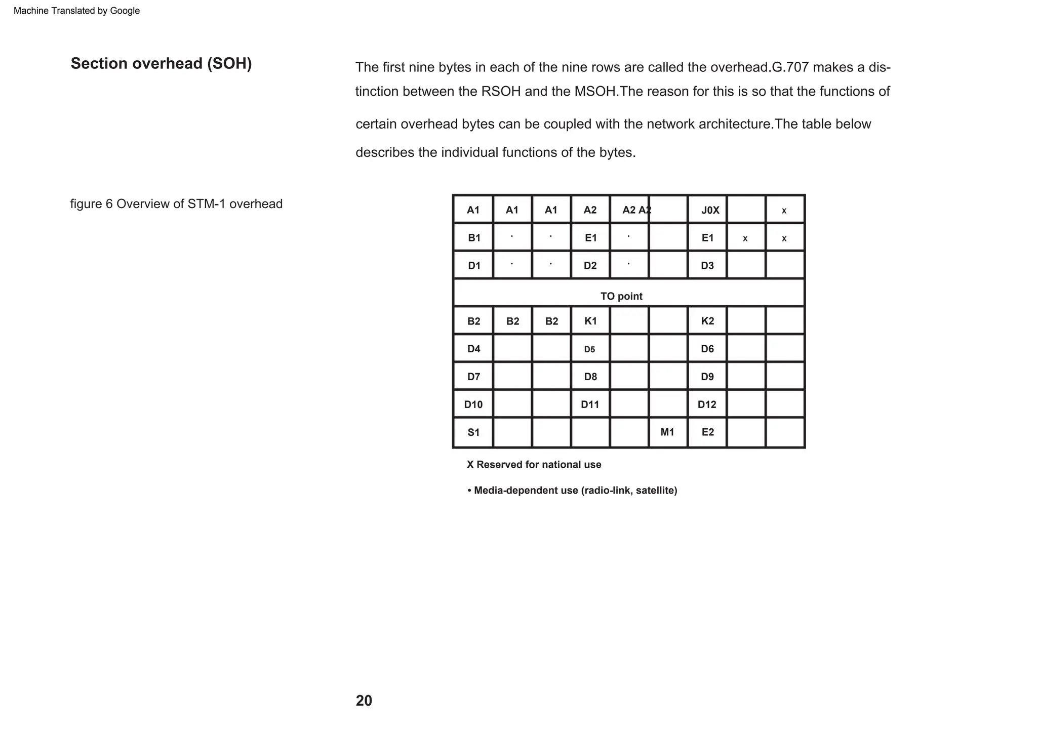
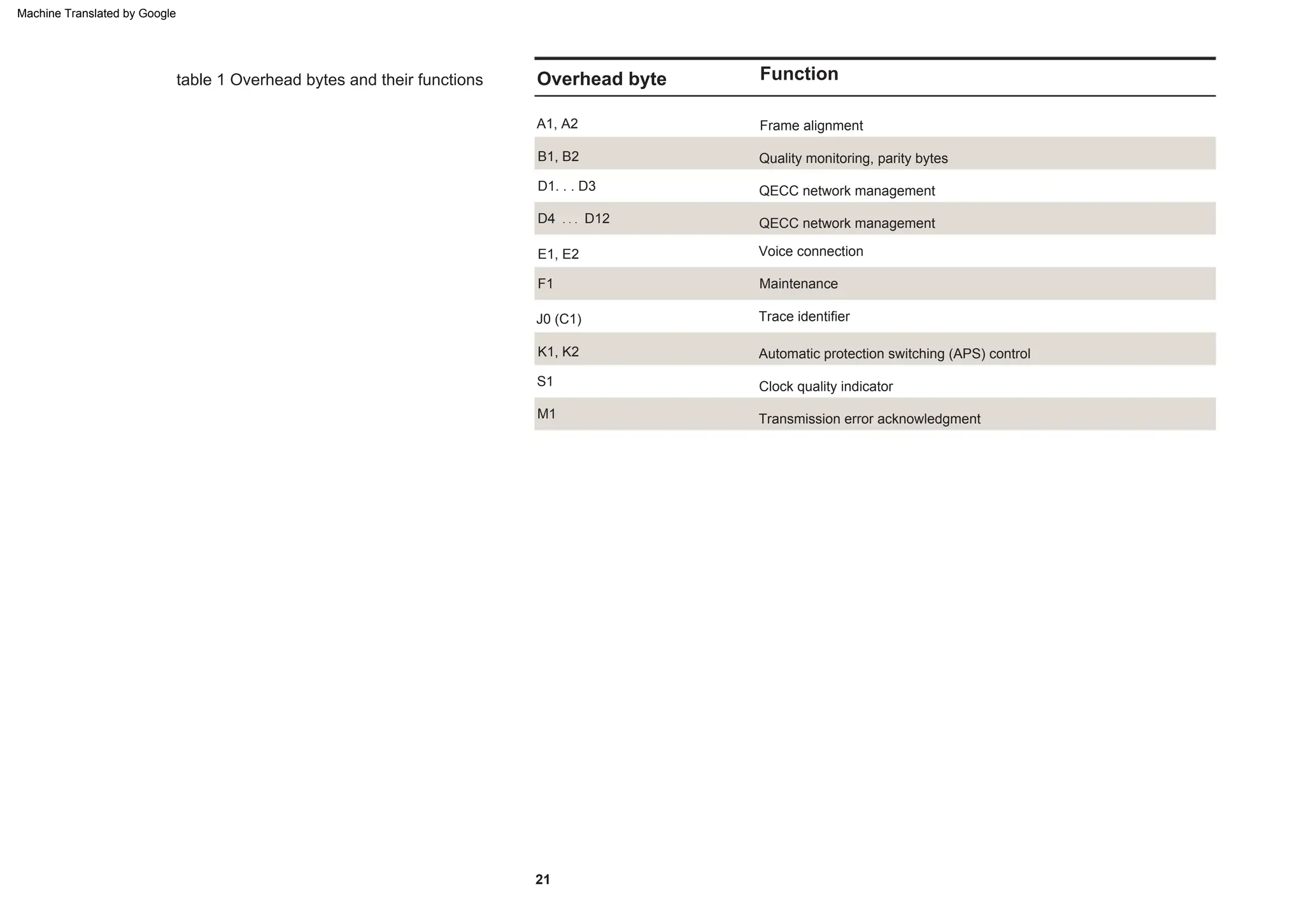
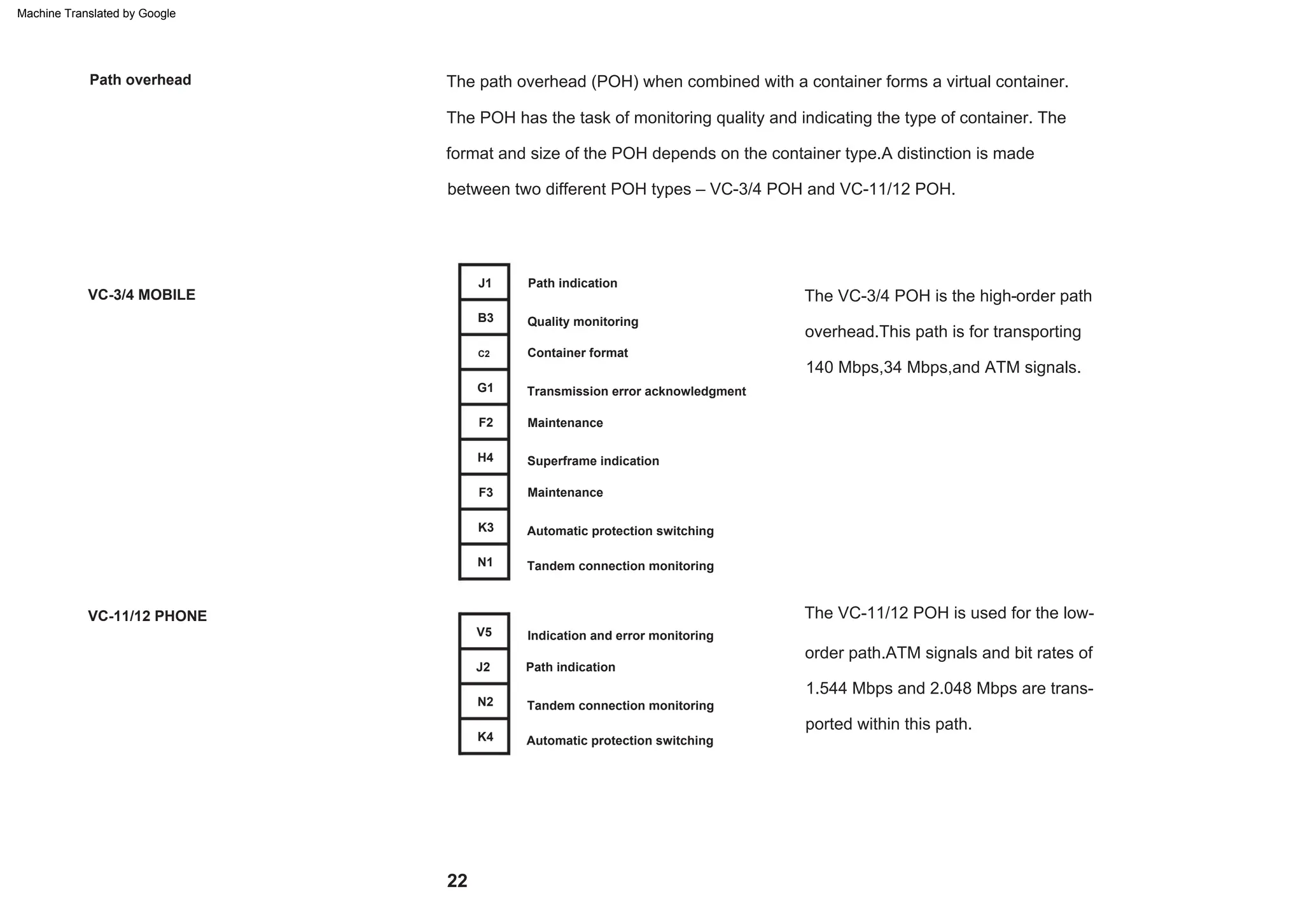
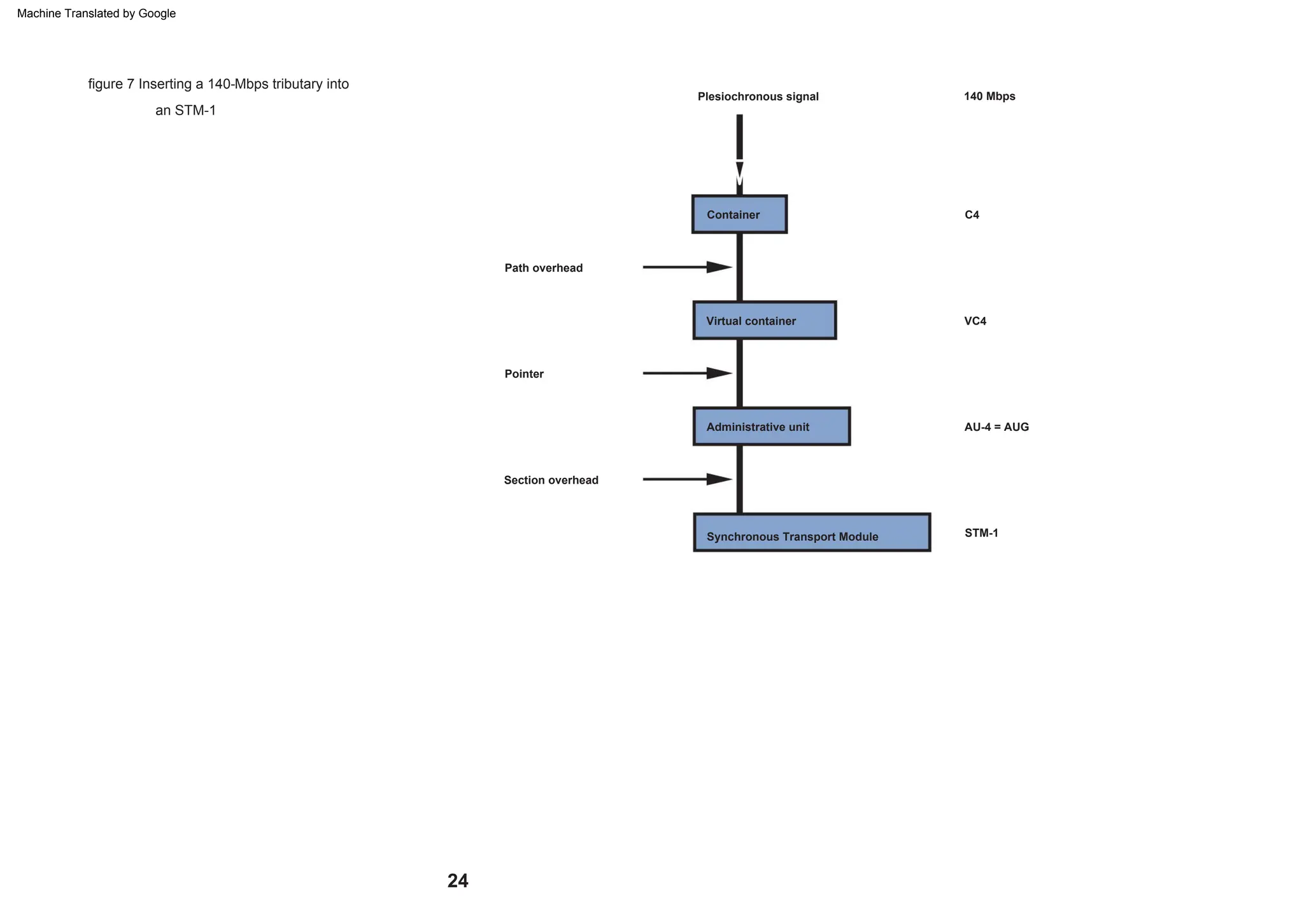
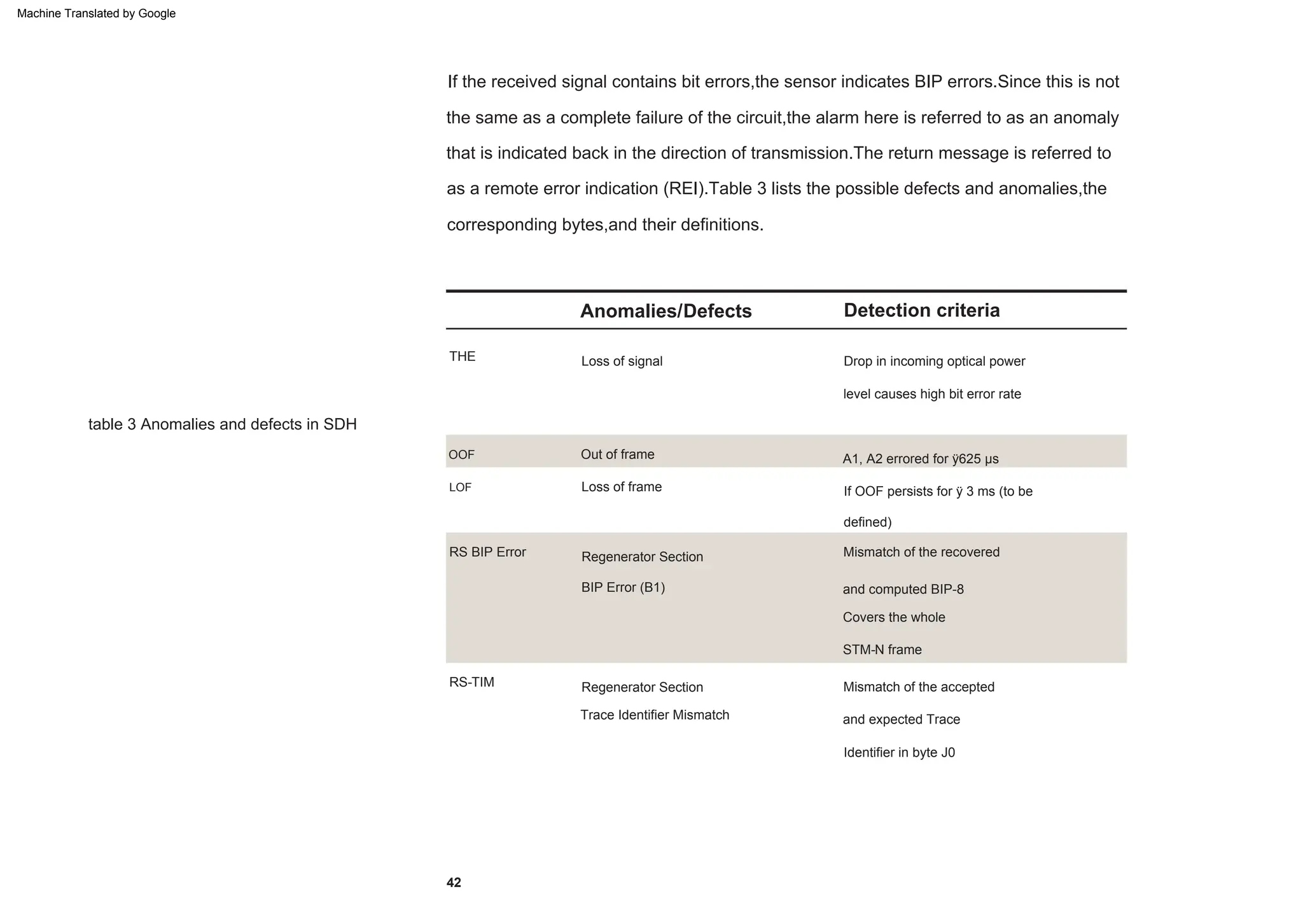
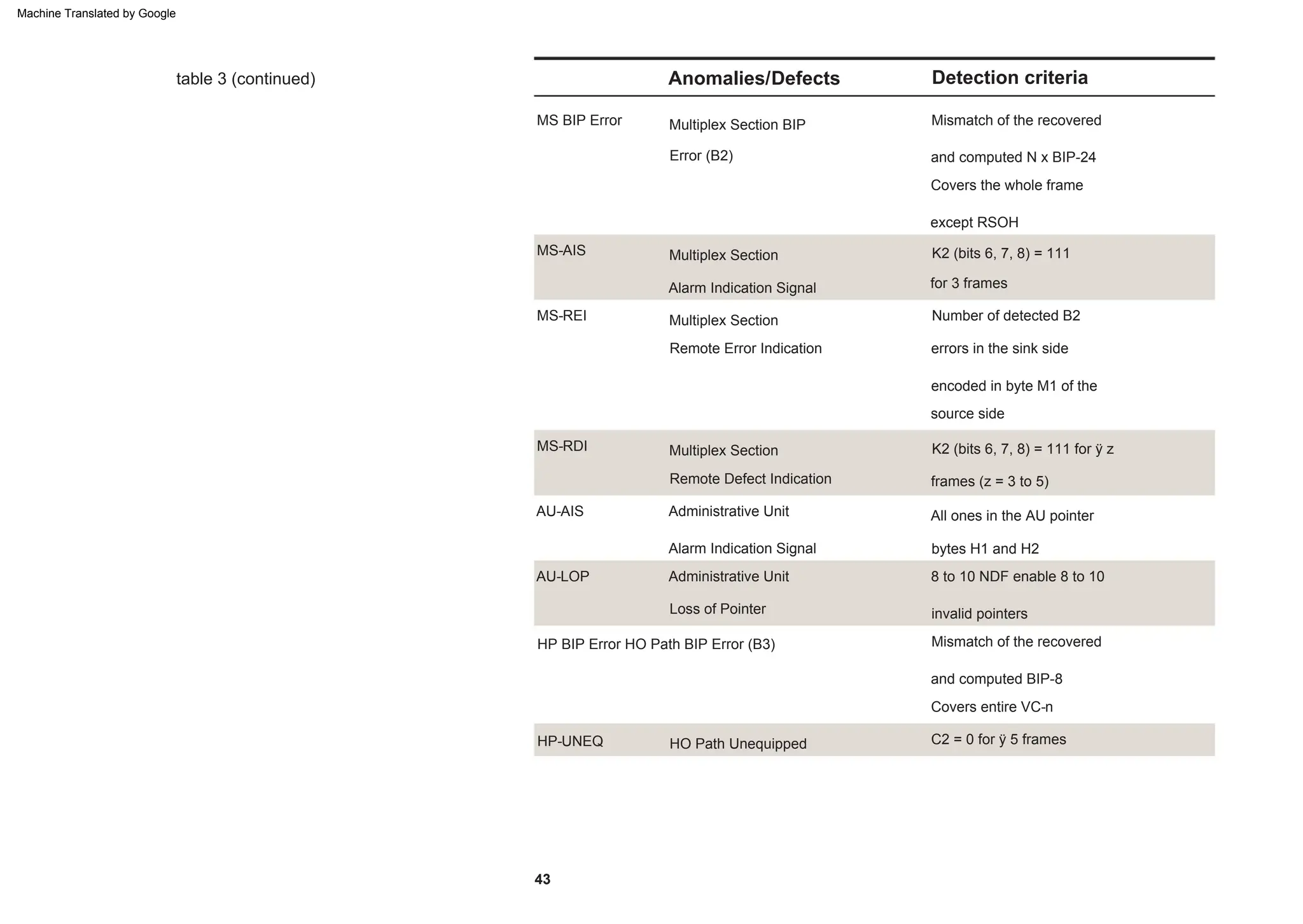
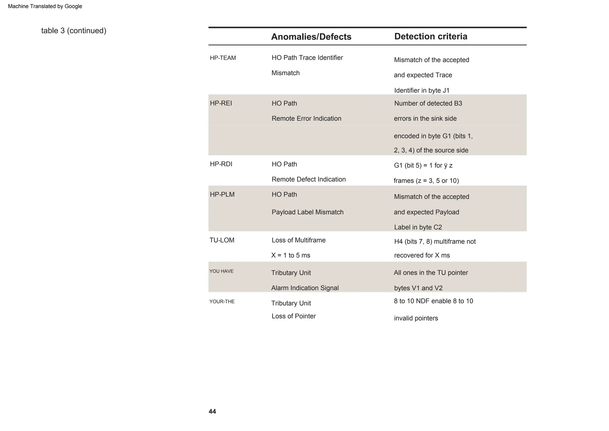
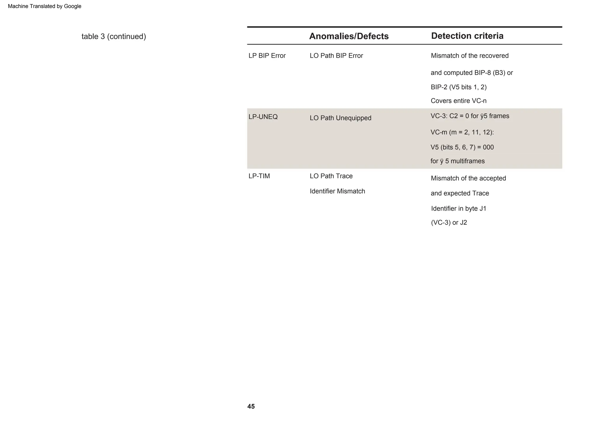
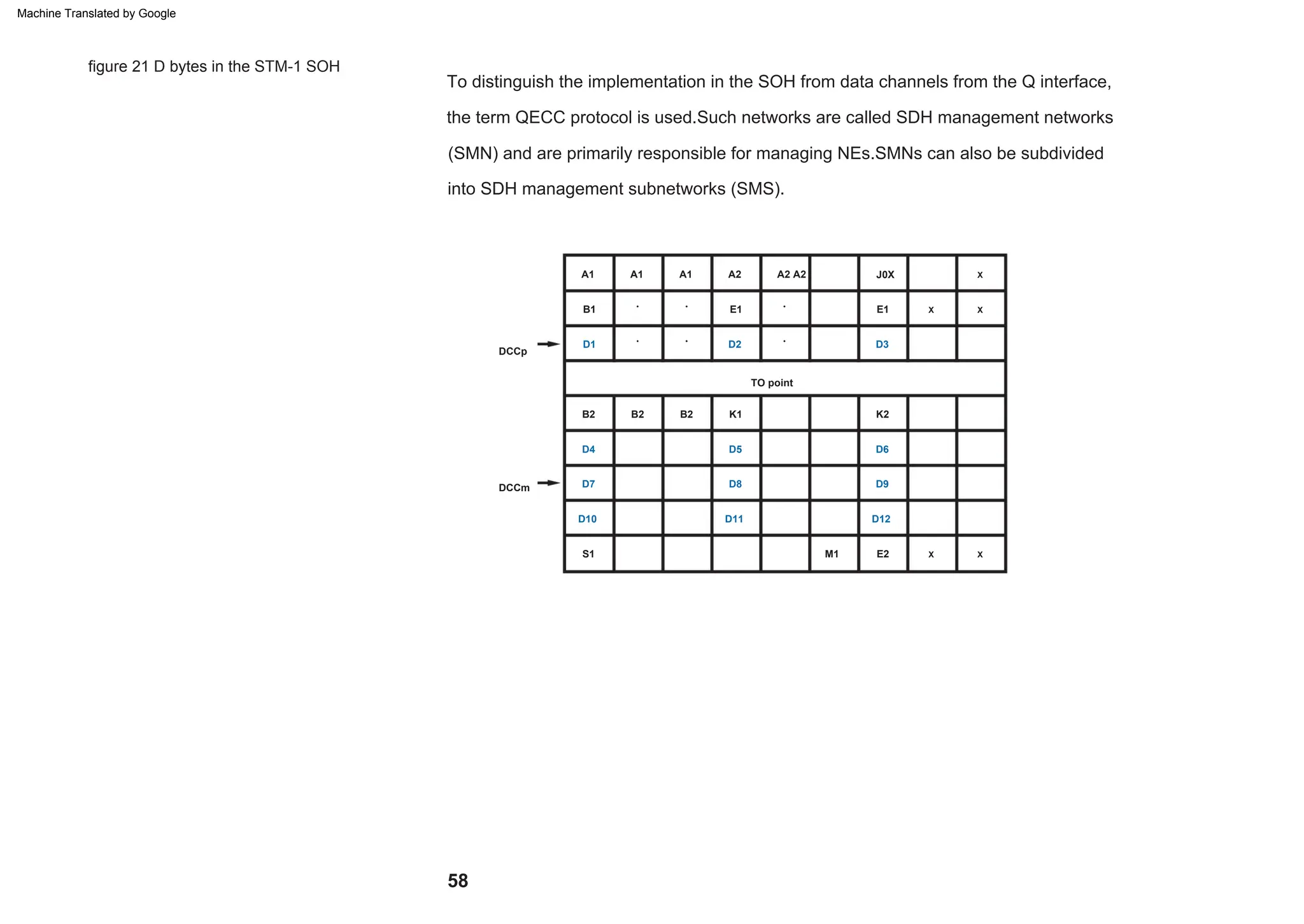
Pocket Guide Synchronous Digital Hierarchy
SDH
Machine Translated by Google
8
39
68
59
The synchronous digital hierarchy in terms of a layer model The components
of a synchronous network The STM-1 frame format
AU-4 contiguous concatenation
The differences between SDH and SONET
Synchronization
77
Transmission at higher hierarchy levels
SDH measurement tasks
14
47
APS time measurements
Tandem connection monitoring (TCM)
Abbreviations
Overview of current ITU-T recommendations relevant to SDH
23
55
Why SDH?
Automatic protection switching (APS)
62
How are PDH,ATM and IP signals transported by SDH?
Telecommunications management network (TMN) in the SDH network
31
Sensor tests
4
38
64
Pointer procedures
40
70
AU-4 virtual concatenation
11
ITU-T error performance recommendations
Error and alarm monitoring
Jitter measurements
19
53
Introduction
36
62
80
28
Content
Machine Translated by Google
In the field of communications engineering,this resulted
in the introduction of frequency division multiplex (FDM) sys-
tems whereby each individual telephone channel was
modulated with a different carrier frequency.The signals could
then be shifted into different frequency ranges enabling several
telephone connections to be transmitted over a single cable.
With some 750 million telephone connections in use today and
the number of Internet users continuing to grow rapidly,net-
work providers have been faced with the task of trying to deal
effectively with increased telephone traffic.In response to the
growing market needs,a number of methods and technologies
have been developed within the last 50 years to address these
market needs in as economical a way as possible.
With the advent of semiconductor circuits and the continuing demand for
telephone capacity,a new type of transmission method,pulse code
modulation (PCM) was developed in the 1960s.
Introduction
4
Machine Translated by Google
5
This is known as the primary rate and is used throughout the world with
the exception of the USA,Canada,and Japan,where a primary rate of 1544
kbps (formed by combining 24 channels) is used.
With PCM (multiple use of a single line by means of digital time-domain
multiplexing),the analog telephone signal is first sampled at a
bandwidth of 3.1 kHz,quantized and encoded then transmitted at a bit rate of
64 kbps.When 30 such coded chan-nels are collected together into a
frame along with the necessary signaling information, a transmission rate of
2048 kbps is achieved.
The demand for greater bandwidth however,meant that more stages of
multiplexing were needed throughout the world.A practically synchronous
– or plesiosynchronous – digital hierar-chy was developed in response.As
there are slight differences in timing signals,justification or stuffing is
necessary when forming the multiplexed signals.
Machine Translated by Google
6
This pocket guide aims to provide an introduction to synchro-
nous communications without going into the “bits and bytes”.
Inserting or dropping an individual 64-kbps channel to or from a
higher digital hierarchy however requires a considerable
amount of complex and expensive multiplexer equipment.
Towards the end of the 1980s,the synchronous digital hierarchy
(SDH) was introduced,paving the way for a worldwide,unified
network structure.SDH is ideal particularly for network
providers,as it delivers an efficient,economical network man-
agement system that can be easily adapted to accommodate
the demand for “bandwidth-hungry”applications and services.
Machine Translated by Google
6312 kbps
x 3
34368 kbps
5.
North American standard
x 4
8448 kbps
x 30
x 5
1544 kbps
397200 kbps
x 6
4.
x 4
2. order
x 24
44736 kbps
x 4
64 kbps
x 3
Japanese standard
x 3
x 4
3.
397200 kbps
x 4
primary rate
European standard
2048 kbps
x 4
139264 kbps
564992 kbps
32064 kbps
x 7
97728 kbps
transmission rates
figure 1 Summary of plesiochronous
7
Machine Translated by Google
High transmission rates
both difficult and expensive.
digital hierarchy (PDH) evolved.The bit rates start with the basic multiplex rate of 2
the primary rate is 1.5 Mbps with additional stages of 6 and 44 Mbps.This fundamen-tal
difference in developments made the set up of gateways between the networks
the most suitable technology for backbones – the superhighways in today’s telecom-
munications networks.
with the demand for ever-higher bit rates,a multiplex hierarchy or plesiosynchronous
Mbps with further stages of 8,34,and 140 Mbps.In North America and Japan,however
were gradually converted to digital technology during the years that followed.To cope
With the introduction of PCM technology in the 1960s,communications networks
inherent in PDH.In turn,network providers began to benefit from the many techno-
logical and economic advantages this new technology introduced including:
In response to the demand for increased bandwidth,reliability,and high-quality serv-
ice,SDH developed steadily during the 1980s eliminating many of the disadvantages
Transmission rates of up to 10 Gbps can be achieved in modern SDH systems making it
Why SDH?
8
Machine Translated by Google
With SDH,network providers can react quickly and easily to the requirements of their
customers.For example,leased lines can be switched in a matter of minutes.The net-
work provider can use standardized network elements (NE) that can be controlled and
monitored from a central location via a telecommunications management network
(TMN) system.
Modern SDH networks include various automatic back-up circuit and repair mecha-
nisms which are designed to cope with system faults and are monitored by
management.As a result,failure of a link or an NE does not lead to failure of the entire
network.
Compared to the older PDH system,low bit rate channels can be easily extracted from
and inserted into the high-speed bit streams in SDH.It is now no longer necessary to
apply the complex and costly procedure of demultiplexing then remultiplexing the
plesiosynchronous structure.
SDH is the ideal platform for a wide range of services including POTS,ISDN,mobile
radio,and data communications (LAN,WAN,etc.).It is also able to handle more recent
services such as video on demand and digital video broadcasting via ATM.
Reliability
Future-proof platform for
new services
High availability and
capacity matching
Simplified add
and drop function
9
Machine Translated by Google
factor.The alternative lies in dense wavelength division multiplexing (DWDM),a tech-
nology enabling the multiple use of singlemode optical fibers.As a result,a number of
equipment costs.
division multiplex,TDM).The current high costs of such NEs however are a restricting
Connected to the introduction of DWDM is the tendency toward the “all-optical net-
work”.Optical add/drop multiplexers (OADM) are already available commercially and
to combine NEs from different manufacturers into a single network thus reducing
The trend in transport networks is toward ever-higher bit rates,such as STM-256 (time
and to SONET systems.The SDH interfaces are globally standardized,making it possible
SDH makes it much easier to set up gateways between different network providers
DWDM layer below the SDH layer (see figure 2).Future systems are therefore quite like-
ly to combine higher multiplex rates with the use of DWDM.
the first field trials are in progress for optical cross connects (OXC).In terms of the ISO-
OSI layer model,this development basically means the introduction of an additional
wavelengths can be used as carriers for the digital signals and transmitted simultane-
ously through the fibers.(See DWDM Pocket Guide for more information.)
Interconnection
10
Machine Translated by Google
The synchronous digital
hierarchy in terms of a layer model
This is usually a glass fiber or possibly radio or satellite link.The regenerator section is
the path between regenerators.Part of the regenerator section overhead (RSOH) is
available for the signaling required within this layer.
SDH networks are subdivided into various layers directly related to the network topol-
ogy.The lowest layer is the physical layer,which represents the transmission medium.
Telecommunications technologies are generally explained using so called layer mod-
els.SDH can also be depicted in the same way.
The remainder of the overhead,the multiplex section overhead (MSOH) is used for
multiplex section needs.The multiplex section covers the part of the SDH link between
multiplexers.The carriers or virtual containers (VC) are available as payload at the two
ends of this section.The two VC layers represent a part of the mapping process.Map-
ping is the procedure whereby the tributary signals,such as PDH and ATM are packed
into SDH transport modules.VC-4 mapping is used for 140-Mbps or ATM signals and
VC-12 mapping is used for 2-Mbps signals.
11
Machine Translated by Google
Multiplex section
VC-4 layer
Regenerator section
PSTN/ISDN
VC-12 layer
IP
ATM
Physical interface
figure 2 The SDH layer model
The uppermost layer represents the applications of the SDH transport network.
12
Machine Translated by Google
13
figure 3 Path section designations
SDH
SDH
PDH
SDH
Regenerator
section
Regenerator
IP
regene-
rator
section
Cross-
connect
SDH
Path
SDH
PDH
section
Multiplex
ATM
multiplexer
SDH
ATM
section
Multiplex
IP
multiplexer
Machine Translated by Google
Figure 4 is a schematic diagram of an SDH ring structure with various tributaries.The
mixture of different applications is typical of the data transported by SDH.Synchro-
nous networks must have the ability to transmit plesiochronous signals as well as the
capability to handle future services such as ATM.This requires the use of the various
NEs which are discussed in this section.
figure 4 Schematic diagram of hybrid com-
munications networks
The components of
a synchronous
network
14
140 Mbps
34 Mbps
STM-1, STM-4
34 Mbps
8 Mbps
DXC 2 Mbps
140 Mbps
TM
ATM
switch
TM: Terminal Multiplexer
ADM
ADM
2 Mbps
2 Mbps
140 Mbps
ADM: Add Drop Multiplexer
DXC: Digital Cross Connect
2 Mbps
34 Mbps
STM-4/-16
AND
STM-4
STM-1
STM-1/STS-3c gateway to SONET
ADM
STM-1
Machine Translated by Google
Regenerators
STM-N
STM-N
Regenerator
Regenerators,as the name implies,have the job of regenerating the clock and ampli-
tude relationships of the incoming data signals which have been attenuated and
Messages are received by extracting various 64-kbps channels (for example service
or mesh structure) is governed by the requirements of the network provider.
Current SDH networks are comprised of four types of NE.The topology (that is the ring
using these channels.
distorted by dispersion.They derive their clock signals from the incoming data stream.
channels E1,F1) in the regenerator section overhead (RSOH) and can also be output
15
Machine Translated by Google
STM-N
multiplexer
STM-N
Add/Drop
STM-N
Terminal
SDH
PDH
Multiplexer
SDH
PDH
Plesiochronous and lower bit rate synchronous signals can be extracted
from or inserted into high-speed SDH bit streams by means of ADMs.
This feature makes it possible to set up ring structures, which have the
advan-tage that in the event of a fault, automatic back-up path
switching is possible using elements in the ring.
Terminal multiplexers are used to combine plesiochronous and synchronous
input signals into higher bit rate STM-N signals.
Add/drop multiplexers (ADM)
Terminal multiplexers
16
Machine Translated by Google
STM-1
STM-4
140 Mbps 140 Mbps
STM-1
STM-16
STM-4
STM-16
34 Mbps
34 Mbps
2 Mbps
Cross-connect
2 Mbps
Digital cross-connects (DXC)
This NE has the widest range of functions.It allows mapping of PDH tributary signals
into virtual containers as well as the switching of various containers up to and includ-
ing VC-4.
17
Machine Translated by Google
18
management
Network element
advantage of these fibers is that they are not susceptible to interference and can trans-
mit at very high speeds.The disadvantage is in the relatively high cost of procurement
Optical fibers are the physical medium most commonly used in SDH networks.The
and installation.Singlemode fibers are the medium of choice in the first and second
in linking such paths into the network management system are a disadvantage.
found on page 55).All the SDH network elements mentioned so far are software-con-
trolled and can thus be monitored and remotely controlled – one of the most
important features of SDH.
in the synchronous network (more information on TMN in the SDH network can be
The telecommunications management network (TMN) is also regarded as an element
when setting up transmission paths quickly,as part of a mobile radio network or in dif-
ficult terrain.However,the limited bandwidth (currently up to STM-4) and complexity
SDH signals can also be transmitted via radio link or satellite paths – a flexible option
optical windows (1310 nm and 1550 nm).
Machine Translated by Google
The STM-1 frame
format
figure 5 Schematic diagram of STM-1 frame
The STM-1 frame is capable of transporting any PDH tributary signal (ÿ140 Mbps).
A frame with a bit rate of 155.52 Mbps is defined in ITU-T recommendation G.707 and
is known as the synchronous transport module (STM).Since this frame is the first level
of the synchronous digital hierarchy,it is known as STM-1 (see figure 5).It comprises
a byte matrix of 9 rows and 270 columns.Transmission is row by row,starting with
the byte in the upper left corner and ending with the byte in the lower right
corner.The frame repetition rate is 125 ms.Each byte in the payload represents a 64-kbps channel.
19
270
RSOH
3
4
5
TO point
1
1
Transmit
row by row
270 columns (Bytes)
Payload (transport capacity)
MSOH
9
Machine Translated by Google
The first nine bytes in each of the nine rows are called the overhead.G.707 makes a dis-
tinction between the RSOH and the MSOH.The reason for this is so that the functions of
certain overhead bytes can be coupled with the network architecture.The table below
describes the individual functions of the bytes.
figure 6 Overview of STM-1 overhead
Section overhead (SOH)
20
K1
X
•
A2 A2
B2 B2
D8
K2
•
D7 D9
B1 E1
E2
• Media-dependent use (radio-link, satellite)
X Reserved for national use
A1
D3
TO point
S1
X
D5
B2
A2
D6
D2
•
D11
J0X
•
D4
A1
D12
D10
M1
D1
X
E1
•
•
A1
Machine Translated by Google
Function
Overhead byte
table 1 Overhead bytes and their functions
D4
Voice connection
D12
K1, K2 Automatic protection switching (APS) control
S1
QECC network management
Trace identifier
J0 (C1)
QECC network management
F1
Frame alignment
M1
21
Quality monitoring, parity bytes
Maintenance
. . .
Clock quality indicator
Transmission error acknowledgment
A1, A2
B1, B2
D1. . . D3
E1, E2
Machine Translated by Google
F3
Path indication
J2
H4
K3
Transmission error acknowledgment
Superframe indication
Maintenance
N2
G1
V5
F2
Tandem connection monitoring
Quality monitoring
B3
Tandem connection monitoring
Automatic protection switching
C2 Container format
N1
Maintenance
Indication and error monitoring
K4
Automatic protection switching
Path indication
J1
The POH has the task of monitoring quality and indicating the type of container. The
format and size of the POH depends on the container type.A distinction is made
between two different POH types – VC-3/4 POH and VC-11/12 POH.
The VC-3/4 POH is the high-order path
overhead.This path is for transporting
140 Mbps,34 Mbps,and ATM signals.
The path overhead (POH) when combined with a container forms a virtual container.
The VC-11/12 POH is used for the low-
order path.ATM signals and bit rates of
1.544 Mbps and 2.048 Mbps are trans-
ported within this path.
VC-3/4 MOBILE
Path overhead
VC-11/12 PHONE
22
Machine Translated by Google
How are PDH, ATM
and IP signals
transported by SDH?
Where synchronous tributaries are mapped,fixed fill bytes are inserted instead of jus-
tification bytes.A virtual container (VC-n) is made up of the container formed,
together with the path overhead (POH).This is transmitted unchanged over a path
through the network.The next step towards formation of a complete STM-N signal is
the addition of a pointer indicating the start of the POH.The unit formed by the pointer
and the virtual container is referred to as the administrative unit (AU-n) or tributary
unit (TU-n).
Theremaining capacity is partly used for justification (stuffing) in order to equalize
out-timing inaccuracies in the PDH signals.
The heterogeneous nature of modern network structures has made it necessary for all
PDH,ATM.and IP signals to be transported over the SDH network.The process
of matching the signals to the network is called mapping.The container is the basic
pack-age unit for tributary channels. A special container (C-n) is provided for each
PDH tributary signal and is alwayssignificantlylargerthanthepayloadtobetransported.
Several TUs together form a tributary unit group (TUG-n) that in turn is collected
together into a VC.One or more AUs form an administrative unit group (AUG).Finally,
the AUG plus the SOH form the STM-N.
23
Machine Translated by Google
Virtual container
Path overhead
VC4
Administrative unit
Container C4
140 Mbps
Plesiochronous signal
AU-4 = AUG
Section overhead
Synchronous Transport Module
Pointer
STM-1
figure 7 Inserting a 140-Mbps tributary into
an STM-1
24
Machine Translated by Google
IP – Internet Protocol The increased Internet traffic requires a technology to transport the IP packets to the
physical layer.This transport below IP is described by Packet over SONET/SDH,as
one possible route.
This transmission can be achieved via alternative routes,two of which are illustrated in
figure 8.
Since the container transport capacity does not meet the continually increasing ATM
bandwidth requirement,methods have been developed for transmitting the ATM
payload in a multiple (n) C-4 (virtual or contiguous concatenation).As an example, a
quadruple C-4 can be transmitted in an STM-4 (see section on “Contiguous
concatenation”).
ATM signals can be transported in the SDH network in C11,C12,C3,and C4 containers.
From the network layer the IP packets need to be delivered to the underlying layers:
the datalink and physical layers.The actual transmission below the transport layer is
called Packet over SONET/SDH (PoS).
25
Machine Translated by Google
The route chosen (indicated by the solid line) is recommended by the Internet
Engineering Task Force (IETF).
HDLS
SDH/SONET
PPP
IP
ATM
Fiber
figure 8 Alternative routes to transmit IP
packets to the fiber
26
Machine Translated by Google
figure 9 Mapping in SDH
TU-2
VC-4-64c
ATM: 48 384 kbps
x1
x1
x4
x1
AUG64
C-4
x7
ATM: 2 144 kbps
TUG-3
VC-11
STM-16
ATM/IP: 9 584 640 kbps
VC-12
VC-3
STM-256
x1
x4
ATM/IP: 2 396 160 kbps
x1
x1
VC-4
DS1: 1 544 kbps
VC-4-4c
AUG16
E3: 34 368 kbps
C-2
TU-11
ATM/IP: 38 338 560 kbps
AUG16
AU-4-256c
E4: 139 264 kbps
x1
AU-4-16c
DS2: 6 312 kbps
STM-64
x3
ATM/IP: 599 040 kbps
TU-12
STM-0
x4
x4
AUG16
x7
STM-1
C-4-256c
STM-4
x4
VC-2
DS3: 44 736 kbps
AU-3
ATM: 149 760 kbps
x3
x1
x1
ATM: 1 600 kbps
C-4-16c
AU-4-64c C-4-64c
AU-4-4c
VC-3
x1
TUG-2
C-12
x3
x1
C-11
ATM: 6 874 kbps
VC-4-256c
VC-4-16c
x1
x1
C-4-4-c
Pointer processing
AUG256
AU-4
x1
C-3
TUG-3
E1: 2 048 kbps
27
Machine Translated by Google
rate is transmitted over an optical cable system,the signal is designated OC-1 (optical
equivalent of SDH – began in the USA during the mid 1980s.SONET has a base bit
rate of 51.84 Mbps and is designated STS-1 (synchronous transport signal).When bit
container).Table 2 details the additional SONET and equivalent SDH signals and bit
SDH is used worldwide with the exception of the USA,Canada,and Japan.Specification
on the synchronous optical network (SONET) transmission technology – the American
sub-STM or STM-0 signal,an interface used in SDH/SONET links,radio links and
satellite connections.The STM-0 has a bit rate of 51.84 Mbps.
Figure 9 gives an overview of the mappings currently possible according to ATM
mapping and ITU-T recommendation G.707.A point worth mentioning is the so-called
rate levels in the hierarchy.
and SONET
The differences between SDH
28
Machine Translated by Google
table 2 SONET/SDH signal and bit
rate hierarchy
STS-192*
OC-48
STS-1
OC-192
STM-4
STM-16
STM-64
OC-12
STM-0
STM-1
STS-48*
OC-3
51.84 Mbps
155.52 Mbps
622.08 Mbps
2488.32 Mbps
9953.28 Mbps
39813.12 Mbps
STS-12
STS-768
OC-1
STM-256
29
STS-3
OC-768
Bit rates
SONET signal Equivalent SDH signal
As the table indicates,there are points where transition between SDH and SONET
systems are possible.Matching is relatively simple,as gateway issues were taken
into consideration during development of SDH.Only minor adjustments need to be
and OC-192 are currently utilized.
These hierarchy levels basically match the plesiosynchronous bit rates commonly
used in these countries.Of all the levels listed above,only STS-1,OC-3,OC-12,OC-48
made to certain overhead bytes.SONET terminology is however,quite different with
the packing unit for example referred to as a virtual tributary (VT-n) as opposed to
virtual container.
Machine Translated by Google
figure 10 SONET multiplexing scheme
ATM/IP:
2 396 160 kbps
VT2 SPE
E4: 139.264 kbps
ATM
DS3: 44.736 kbps E3:
34.368 kbps ATM
x1
STS-192c
x1
STS-12c SPE
x7
STS-N
VT2
STS-1
STS-768c
x1,4,16,32
VT6 SPE
x1
ATM/IP:
599 040 kbps
STS-48c
ATM/IP:
2 396 160 kbps
VT1 SPE
VT3
ATM/IP:
38 338 560 kbps
STS-192c SPE
STS-3c
x4
VT-group
x1.4
x1,4,16,64,192
Pointer processing
x3
STS-768c SPE
STS-12c
STS-1 SPE
ATM/IP:
2 396 160 kbps
STS-48c SPE
x1,3,12,48,192,768
ATM/IP:
599 040 kbps
VT 1.5
x1,4,16
ATM/IP:
9 584 640 kbps
STS-3c SPE
30
Machine Translated by Google
Pointer procedures
Figure 11 illustrates the pointer procedure using C3 mapping as an example.
The use of pointer procedures also gives synchronous communications a distinct
advantage over the plesiochronous hierarchy.Pointers are used to localize individual
virtual containers in the payload of the synchronous transport module.The pointer
may directly indicate a single VC-n virtual container from the upper level of the STM-1
frame.Chained pointer structures can also be used.The AU-4 pointer initially indicates
the VC-4 overhead.Three further pointers are located at fixed positions in the VC-4 and
are used to indicate the start of the three VC-3 virtual containers relative to the VC-4.
31
Machine Translated by Google
N1
J1
H4
260
H2
J1
C2
F2
H4
K3
J1
H4
N1
MSOH
H3
G1
B3
RSOH
F2
F3
H1
C2
F3
9
H2
G1
H4
J1
84
K3
B3
F3
K3
J1
H3
H4
34 Mbps
F2
H1
C2
K3
F2
N1
261
H2
F3
B3
F3
H1
G1
K3
B3
G1
N1
G1
Fixed justification C2
B3
N1
TO point
H3
C2
F2
C-3
figure 11 Schematic diagram of C-3 mapping
32
Machine Translated by Google
33
SDH multiplexers are controlled from a highly accurate central clock source running
at 2.048 MHz.Pointer adjustment may be necessary if phase variations occur in the
real network or if the connection is fed through the networks of different providers.The
AU pointer can be altered in every fourth frame with prior indication.The virtual
container is then shifted by precisely three bytes.Pointer activity is therefore a good
indication of clock variations within a network.
Machine Translated by Google
Negative justification bytes
Frame n+1
Frame n+2
Virtual
Frame n
Virtual
Container
SOH
Frame n+3
Container
If the pointer is shifted to a later point in time (to the right in figure 12),the three bytes
immediately preceding it are ignored.If the transmitting source is in advance of the
actual clock,space for extra capacity must be provided.This takes place at the
pointer position into which three bytes are inserted each time.If a further clock
adjustment is not made,this configuration is propagated throughout the network.
figure 12 Negative pointer justification
34
Machine Translated by Google
35
to locate every user channel from each STM-N frame,which considerably simplifies
When a multiplex bundle is resolved,pointer procedures make it immediately possible
drop and insert operations within a network node.In contrast,complete demultiplex-ing
of every level of a plesiochronous hierarchy signal is required in order to access a
particular tributary channel.
can be corrected by appropriate pointer actions.Such changes and shifts in phase can
be caused by changes in propagation,delay in the transmission medium or by non-
synchronous branches in the real network.
structure in the form of virtual containers without the need for larger buffers.Howev-
er,changes in the phase location of the virtual container relative to the superior frame
This allows for the free insertion in time of user signals into the next higher frame
Machine Translated by Google
This mechanism is provided to allow bit rates in excess of the capacity of the C-4
container to be transmitted.For example,the AU-4-4c is intended for transporting B-
ISDN bit rates.The advantage of this method is that the payload does not have to be
split up,since a virtually contiguous container is formed within an STM-4.The payloads
of several consecutive AU-4s are linked by setting all the pointers to a fixed value – the
concatenation indicator (CI) – with the exception of the pointer for the first AU-4. If
pointer activity becomes necessary,this takes place for all concatenated AU-4s equally.
Figure 13 illustrates how the payload of ATM cells can be transmitted as a whole.
AU-4 contiguous concatenation
36
Machine Translated by Google
Fixed
Fixed Fixed
G1
C2
4 x 9 bytes
F2
N1
MSOH
C-4-4c
J1
F3
K3
B3
RSOH
AU-4 Pointers
H4
4 x 261
VC-4-4c
ATM cell
STM-4
figure 13 Virtual concatenation
37
The first pointer indicates byte J1.All other pointers are set to concatenation indication
(CI) ATM Cell.
Machine Translated by Google
VC-4-4c
SDH cross-connect for VC-4
In
Out
VC-4-4c
STM-4c port
In Out
VC-4
622 Mbps
In
ATM
switch
STM-4c port
150 Mbps
VC-4
STM-4c port
Out
VC-4
622 Mbps
600 Mbps
In ATM
switch
STM-4c port
Out
600 Mbps
VC-4
Ensuring the integrity of the payload is the task of the NE on the receiving side.These
NEs reassemble the payload of the individual virtually concatenated VC-4s into a unit,
even if different pointer values are present.
If the cross-connects in the SDH network are unable to switch complete VC-4-4cs,the
method described previously cannot be used to transmit ATM payloads.On the
transmit side,four complete VC-4s with four identical pointer values are combined into
an AUG.The individual VC-4s are transported independently through the network.
AU-4 virtual
concatenation
38
concatenation
figure 14 Principle of contiguous
Machine Translated by Google
higher hierarchy
Transmission at
levels
STM-256 39813.12 Mbps
To achieve higher bit rates,AU-3/4s are multiplexed into STM-N frames.
9953.28 Mbps
STM-4
705 to No.768) followed by 64 A2 bytes.The other bytes are reserved for future
international standardization.
622.08 Mbps
specified for each stage individually.For this,the A1,A2 and B2 bytes are formed N
times.The frame alignment of an STM-256 frame is composed of 64 A1 bytes (byte No.
2488.32 Mbps
The STM-N frame structures are basically N times the STM-1 structure.For example,
The following hierarchy levels are defined in SDH:
STM-1 155.52 Mbps
the STM-4 overhead is four times the size of the STM-1 overhead.The SOH content is
STM-16
STM-64
39
Machine Translated by Google
Large numbers of alarm and error messages are an integral part of SDH networks.In
SDH,these are referred to as defects and anomalies,respectively.They are coupled to
network sections and the corresponding overhead information.The advantage of this
detailed information is illustrated as follows.
Complete failure of a circuit results for example,in a loss of signal (LOS) alarm in the
receiving NE.This alarm triggers a complete chain of subsequent messages in the form
of alarm indications signals (AIS) as shown in figure 15.The transmitting side is
informed of the failure by the return of a remote defect indication (RDI) alarm.The
alarm messages are transmitted in fixed bytes in the SOH or POH.For example,byte
G1 is used for the HP-RDI alarm.
Error and alarm
monitoring
40
Machine Translated by Google
AIS
SDH multiplexer
AIS
K2
B1 B1
MS-RDI
SDH regenerator
LOS/LOF
BIP Err.
G1
MS-BIP
MS-AIS
SDH multiplexer
K2
Multiplex section
M1
HP-REI
Regenerator section
HP-RDI
MS-RDI
STMN alarm scheme
MS-BIP
B1
High order path
MS-RDI
anomalies
figure 15 Overview of major defects and
41
Machine Translated by Google
Drop in incoming optical power
level causes high bit error rate
Trace Identifier Mismatch
THE
A1, A2 errored for ÿ625 µs
Loss of frame
Regenerator Section
RS BIP Error
Mismatch of the accepted
LOF
Loss of signal
RS-TIM
Out of frame
Regenerator Section
Covers the whole
STM-N frame
OOF
If OOF persists for ÿ 3 ms (to be
defined)
BIP Error (B1)
Identifier in byte J0
and expected Trace
and computed BIP-8
Mismatch of the recovered
42
Detection criteria
Anomalies/Defects
that is indicated back in the direction of transmission.The return message is referred to
as a remote error indication (REI).Table 3 lists the possible defects and anomalies,the
the same as a complete failure of the circuit,the alarm here is referred to as an anomaly
If the received signal contains bit errors,the sensor indicates BIP errors.Since this is not
corresponding bytes,and their definitions.
table 3 Anomalies and defects in SDH
Machine Translated by Google
table 3 (continued) Detection criteria
Anomalies/Defects
Administrative Unit
Mismatch of the recovered
errors in the sink side
except RSOH
8 to 10 NDF enable 8 to 10
for 3 frames
and computed N x BIP-24
All ones in the AU pointer
HP BIP Error HO Path BIP Error (B3)
C2 = 0 for ÿ 5 frames
Remote Defect Indication
Multiplex Section BIP
Multiplex Section
AU-LOP
Alarm Indication Signal
MS-RDI
Multiplex Section
HP-UNEQ
AU-AIS
K2 (bits 6, 7, 8) = 111
MS-REI
and computed BIP-8
bytes H1 and H2
Covers the whole frame
Number of detected B2
invalid pointers
Loss of Pointer
Error (B2)
Remote Error Indication
K2 (bits 6, 7, 8) = 111 for ÿ z
frames (z = 3 to 5)
43
Administrative Unit
Alarm Indication Signal
MS BIP Error
Multiplex Section
HO Path Unequipped
Covers entire VC-n
MS-AIS
Mismatch of the recovered
encoded in byte M1 of the
source side
Machine Translated by Google
H4 (bits 7, 8) multiframe not
recovered for X ms
YOUR-THE
and expected Payload
Number of detected B3
TU-LOM
G1 (bit 5) = 1 for ÿ z
frames (z = 3, 5 or 10)
and expected Trace
Payload Label Mismatch
All ones in the TU pointer
bytes V1 and V2
Remote Defect Indication
HP-TEAM
encoded in byte G1 (bits 1,
Alarm Indication Signal
YOU HAVE
HP-RDI
Remote Error Indication
Mismatch
44
Loss of Multiframe
HP-REI
Label in byte C2
Loss of Pointer
HP-PLM
Identifier in byte J1
Mismatch of the accepted
8 to 10 NDF enable 8 to 10
Tributary Unit
Mismatch of the accepted
2, 3, 4) of the source side
HO Path
Tributary Unit
errors in the sink side
HO Path
invalid pointers
X = 1 to 5 ms
HO Path
HO Path Trace Identifier
table 3 (continued)
Detection criteria
Anomalies/Defects
Machine Translated by Google
table 3 (continued) Detection criteria
Anomalies/Defects
LO Path Unequipped
LP-UNEQ
LO Path BIP Error
VC-3: C2 = 0 for ÿ5 frames
(VC-3) or J2
LP-TIM LO Path Trace
and computed BIP-8 (B3) or
BIP-2 (V5 bits 1, 2)
and expected Trace
Identifier in byte J1
Covers entire VC-n
for ÿ 5 multiframes
LP BIP Error
Mismatch of the accepted
VC-m (m = 2, 11, 12):
Identifier Mismatch
45
Mismatch of the recovered
V5 (bits 5, 6, 7) = 000
Machine Translated by Google
2, 3, 4) of the source side
encoded in byte G1 (bits 1,
VC-m (m = 2, 11, 12): If
one or more BIP-2 errors
VC-3: G1 (bit 5) = 1 for ÿz frames
VC-m (m = 2, 11,
Mismatch of the accepted
12):V5 (bit 8) = 1 for ÿz
multiframes (z = 3, 5 or 10)
B3 errors in the sink side
LO Path
Payload Label Mismatch
Remote Defect Indication
LP-REI
46
source side
LP-PLM LO Path
VC-3: Number of detected
LP-RDI
detected in the sink side,
LO Path
and expected Payload
Label in byte C2 or V5 (bits
5, 6, 7)
byte V5 (bits 3) = 1 on the
Remote Error Indication
table 3 (continued)
Anomalies/Defects Detection criteria
Machine Translated by Google
mechanism,which is used for point-to-point connections,and ring protection
mechanism,which can take on many different forms.Both mechanisms use spare
circuits or components to provide the back-up path.Switching is controlled by the
is currently one of the most discussed in SDH. A wide range of standardized mecha-
nisms has been incorporated into synchronous networks in order to compensate for
Two basic types of protection architecture are distinguished in APS:linear protection
overhead bytes K1 and K2.
for users and network providers alike.As a result,the subject of fall-back mechanisms
failures in network elements.
Network failures,whether due to human error or faulty technology,can be expensive
Modern society is almost completely dependent on communications technology.
The simplest form of back-up is the so-called 1 + 1 APS,where each working line is
protected by one protection line.If a defect occurs,the protection agent in the NEs at
acknowledgment in the backward channel.
both ends switches the circuit over to the protection line.The switchover is triggered by a
defect such as LOS.Switching at the far end is initiated by the return of an
Automatic
protection
switching (APS)
Linear protection
Back-up network switching
47
Machine Translated by Google
48
The 1+1 and 1:N protection mechanisms are standardized in ITU-T recommendation
G.783.The reserve circuits can be used for lower-priority traffic,which can simply be
interrupted if the circuit is needed to replace a failed working line.
1+1 architecture includes 100 percent redundancy,as there is a spare line for each
working line.Economic considerations have led to the preferential use of 1:N architec-
ture,particularly for long-distance paths.Here,several working lines are protected by a
single back-up line.If switching is necessary,the two ends of the affected path are
switched over to the back-up line.
Machine Translated by Google
IN
IN
1:1 protection scheme
1+1 protection scheme
P
P
IN
IN
P
1:N protection scheme
figure 16 Linear protection schemes
49
Machine Translated by Google
Figure 17 shows the basic principle of APS for unidirectional rings.Assuming an
interruption in the circuit occurs between network elements A and B,direction y would
There are some basic distinctions to be observed however between ring structures
be unaffected.An alternative path would however have to be found for direction x.The
traffic would be transmitted simultaneously over both the working and protection
cost saving in ring structures when compared with linear structures.A ring is the
simplest and most cost-effective way of linking a number of network elements.
with unidirectional and bidirectional connections.
A number of protection mechanisms are available for this type of network
architecture,some of which have been standardized in ITU-T recommendation G.841.
The greater the communications bandwidth carried by optical fibers,the higher the
the other NEs (C and D) would switch through the back-up path.This is known as a
line-switched process.
A simpler method would be to use the path-switched ring (figure 18). In this case,
protection line and immediately take up the connection.
connection would therefore be switched to the alternative path in NEs A and B while
line.Should there be an interruption,the receiver (in this case A) would switch to the
Unidirectional rings
Ring protection
50
Machine Translated by Google
D D
and
x x
A CA C
and
B
B
and
x
working
line protection line
and
x
figure 17 Two-fiber unidirectional path
switched ring
51
Machine Translated by Google
x
and
x
D
B
x
A CA C
B
and
working
line protection line
and
D
and
x
Bidirectional rings with four fibers provide even greater protection.Each pair of fibers transports
working and protection channels.This results in 1:1 protection,that is 100 percent redundant.This
improved protection is however coupled with relatively high
In this network structure,connections between NEs are bidirectional (figure 18).The overall capacity
of the network can be split up for several paths,each with one bidirec-tional working line.For
unidirectional rings,an entire virtual ring is required for each path.If a fault occurs between
neighboring elements A and B,network element B trig-gers protection switching and controls network
element A by means of the K1 and K2 bytes in the SOH.
costs.
Bidirectional rings
52
line-switched ring (BLSR) working
line protection line
figure 18 Two-fiber bidirectional
Machine Translated by Google
Synchronization
SSU
G.812
SEC
G.813
SSU
G.812
PRC
G.811
SEC
G.813
SEC
G.813
SEC
G.813
If synchronization is not guaranteed,this can result in considerable degradation in
network functionality and even total failure.To avoid such scenarios,all NEs are
synchronized to a central clock.This central clock is generated by a high-precision,
primary reference clock (PRC) unit conforming to ITU-T recommendation G.811.This
specifies an accuracy of 1x10-11.This clock signal must be distributed throughout
the entire network. A hierarchical structure is used,in which the signal is passed on
by the subordinate synchronization supply units (SSU) and synchronous equipment
clocks (SEC).The synchronization signal paths can be the same as those used
for SDH communications.
53
figure 19 Clock supply hierarchy structure
Machine Translated by Google
Clock “islands”must be avoided at all costs,as these drift out of synchronization over
time and lead to total failure.Such islands are prevented by signaling the NEs with the
aid of synchronization status messages (SSM – part of the S1 byte).The SSM informs
the neighboring NE of the clock supply status and is part of the overhead.Certain prob-
lems can arise at the gateways between networks with independent clock supplies.
The clock signal is regenerated in the SSUs and SECs with the aid of phase-
locked loops.If the clock supply fails,the affected NE switches over to a clock source
with the same or lower quality.If this is not possible,the NE switches to holdover
mode.In this situation,the clock signal is kept relatively accurate by controlling
the oscillator, applying the stored frequency correction values for the previous hours
and taking the temperature of the oscillator into account.
SDH NEs can compensate for clock offsets within certain limits by means of pointer
operations.Pointer activity is thus a reliable indicator of clock supply problems.
54
Machine Translated by Google
55
To provide these functions,TMN uses object-oriented techniques based on the open
system interconnection (OSI) reference model.The TMN model comprises one
manager,that handles several agents.The agents in turn each handle several managed
objects (MOs).The manager is included in the operating system (OS) which forms
multiplex section,but can also occur as a logical element such as a virtual connection).
M.3010.The functions of a TMN are expressed as:operation,administration,mainte-
nance,and provisioning (OAM&P).This includes monitoring of network performance
and checking of error messages,among other things.
established in 1989,with the publication by the CCITT (now ITU-T) recommendation
The principle of telecommunications management network (TMN) technology was
are located in the NEs. An MO may be a physical unit,for example a plug-in card,or
the“control center”for the network as a whole or in part.In SDH networks,the agents
TMN can also distinguish between logical management units.For example,one
management unit operates at network level,handling individual NEs.Another
management unit operates at the service level to monitor billing charges for example.
s management
network (TMN) in
Telecommunication
the SDH network
Machine Translated by Google
56
reference for CMIP.CMIP is also used where several TMNs or their managers are linked
is where the exchange of data between manager and agent takes place,is the point of
together via the X interface.
Since large quantities of data are not generally required for exchanging information in
the TMN,the capacity of the embedded communication channels (ECC) or data
communication channels (DCC) is sufficient when managing SDH networks.Channels
form of CMIP.SNMP is mainly used in data communications,however,and cannot cope
with the requirements of large telecommunications networks.The Q3 interface,which
common management information protocol (CMIP).The simple network manage-ment
protocol (SNMP) is often mentioned in this context and is basically a simplified
These tasks are performed in modern telecommunications networks by using the
D1 to D3 with a capacity of 192 kbps (DCCp) are used for SDH-specific NE management.
Channels D4 to D12 with a capacity of 576 kbps (DCCm) can be used for non
SDH-specific purposes.
Machine Translated by Google
QECC
QECC
QECC
Local
Manager
x
YOU
DXC DXC
ADM
YOU
Q
ADM
NO
Q
YOU
Q Interfaces: X.25, ISDN, LAN
Central
NO
x
Manager
Central
figure 20 TMN overlay
57
ADM
Machine Translated by Google
X
K2
X
D2
•
X
J0X
A2
DCCp
B2
DCCm
•
A1
D11
D10
X
B1
D5
D4
D12
•
TO point
D3
D6
•
E1 E1
B2
X
S1
A1 A2 A2
•
M1
D7 D8
D1
•
E2
D9
B2 K1
A1
To distinguish the implementation in the SOH from data channels from the Q interface,
the term QECC protocol is used.Such networks are called SDH management networks
(SMN) and are primarily responsible for managing NEs.SMNs can also be subdivided
into SDH management subnetworks (SMS).
figure 21 D bytes in the STM-1 SOH
58
Machine Translated by Google
SDH measurement
tasks
The measurement facilities built into the system provide only an approximate
location of a fault.Separate measuring equipment in contrast,is of much greater use
particularly when monitoring individual channels,and more data relevant to clearing
the fault can be obtained.The only areas that are covered by both network manage-
ment and measurement procedures are long-term analysis and system monitoring.
Although trouble-free operation of all NEs should have been guaranteed by
standardization on the part of various bodies (ITU,ETSI,ANSI,Bellcore),problems still
arise,particularly when NEs from different sources are linked together.Transmission
problems also occur at gateways between networks run by different providers.
Separate measuring equipment,of course,finds further application in the fields of
research and development,production,and installation.These areas in particular
require test equipment with widely differing specifications.
59
Machine Translated by Google
long-term analyses reliably and quickly.
capable of performing test sequences in order to reproduce repeat measurements and
With network providers,fault clearance and maintenance are the main areas of
deployment for measuring equipment.The continuing process of network optimiza-
tion is also a major area in which test equipment needs to be portable.It must also be
that check everything operates as it should.The equipment is then installed on the
customer’s site and put into operation.Test equipment is essential at this stage to
eliminate any faults that may have occurred during production and installation and
to verify correct functioning.Such test equipment needs to be portable,robust,and
or entire networks according to customer requirements and use measuring techniques
In production and installation for example,systems manufacturers configure their NEs
with a rapid,easily interpreted display of results.
reasonably priced,suitable for in and out-of-service measurements,and provide users
60
Machine Translated by Google
Generally speaking SDH test equipment must also be capable of fulfilling the
following measurement tasks:
Alarm analysis
– In-service SDH measurements:
– Mapping analysis
Path trace monitoring
– Jitter and wander analysis
Some of these measurements are discussed in more detail below.
– Testing of automatic protection switching (APS)
Measurements on the TMN interface
– Error performance measurement
– Simulation of pointer activity
Drop and insert measurements
– Measurements on add/drop multiplexers
– Delay measurements
Checking network synchronization
Pointer analysis
– Alignment of port interfaces
– Measurements with structured test signals
Checking the system’s in-built sensors
61
Machine Translated by Google
62
APS time measurements
Sensor tests
Defects result in the interruption of a connection.As an example,an NE must react to
an LOS alarm by sending an AIS to the subsequent NEs and transmitting an RDI
signal in the return path (figure 10).
This function is controlled using overhead bytes K1 and K2.Switching over to the
protection line must take place in less than 50 ms.External equipment is needed to
ensure this and to measure the response time,that is the loss of a specific test pattern
or triggering of a preset alarm when a connection is intentionally interrupted (figure
22).The measurement is important as a delayed response can result in considerable
degradation in performance and even total failure of the network leading to loss of
income for the network provider.
A special mechanism operates in SDH networks in the event of a fault that allows the
faulty link to be automatically rerouted over a back-up circuit (see APS section above).
These measurements are performed in order to check the reaction of system
components to defects and anomalies.Anomalies are faults such as parity errors.
Machine Translated by Google
63
figure 22 Checking APS response time
SOH byte capture
STM-16
ADM
ANT-20
STM-16
ADM
ADM
STM-1
APS time
measurement
ADM Rx
ANT-20
working line
protection line
STM-16
Machine Translated by Google
64
G.821
ITU-T error performance
recommendations
– Severely errored second (SES):a one-second time interval in which the bit error ratio
– Errored second (ES):a one-second time interval in which one or more bit errors occurs.
exceeds 10–3.
– Unavailable second (US):a circuit is considered to be unavailable from the first of at least
This recommendation was originally specified for international circuit-switched n x 64 kbps
connections and expanded to include higher bit rates.A hypothetical reference connection is the
basis used for determining quality parameters and comprises an international long-distance
segment,a national segment and a subscriber access segment.
G.821 definitions:
parameters.
The quality of digital links is determined with the aid of bit error ratio tests (BERT).The results
of such measurements must,however,be classified in some way,not least because the quality of
a transmission path is often the subject of a contract between the network provider and the
telecommunications user.For this reason,an objective means of classifying a line as either “good”or
“bad”is required.The ITU-T recommen dations G.821,G.826,G.828, G.829,M.2100,and M.2101 are
internationally recognized standards which specify these
seconds which are not SESs.
ten consecutive SESs.The circuit is available from the first of at least ten consecutive
Machine Translated by Google
65
This recommendation,issued in 1993,takes higher bit rates into account and allows in-service
measurement as it relies on the evaluation of block errors.
G.826 definitions include:
– Errored second (ES):a one-second,time interval containing one or more errored
blocks.
– Derived parameter: –
Error-free second (EFS):a one-second,time interval in which no bit errors occur.
The disadvantage of this method is that it relies on the evaluation of bit errors and so the test
channel must be taken out of service to perform the measurement.
exceeds 10–6.
The original version of G.821 also included: –
Degraded minute (DM):a one-minute time interval in which the bit error ratio
– Severely errored second (SES):a one-second,time interval in which more than 30 percent
of the blocks are errored or which contains at least one severely disturbed period (SDP).
– Background block error (BBE):an errored block that is not an SES.
– Unavailable second (US):see under G.821,above.
– Errored block (EB):a block containing one or more errored bits.
G.826
Machine Translated by Google
65
This recommendation,issued in 1993,takes higher bit rates into account and allows in-service
measurement as it relies on the evaluation of block errors.
G.826 definitions include:
– Errored second (ES):a one-second,time interval containing one or more errored
– Errored block (EB):a block containing one or more errored bits.
– Derived parameter: –
Error-free second (EFS):a one-second,time interval in which no bit errors occur.
The disadvantage of this method is that it relies on the evaluation of bit errors and so the test
channel must be taken out of service to perform the measurement.
exceeds 10–6.
The original version of G.821 also included: –
Degraded minute (DM):a one-minute time interval in which the bit error ratio
– Background block error (BBE):an errored block that is not an SES.
– Unavailable second (US):see under G.821,above.
– Severely errored second (SES):a one-second,time interval in which more than 30 percent
of the blocks are errored or which contains at least one severely disturbed period (SDP).
blocks.
G.826
Machine Translated by Google
66
A period of consecutive SES can have the same effect as a microinterruption and may
lead to a severe impairment of the service supported by the SDH path.
The results are referred to as the measurement time.This gives the following error
parameters:errored seconds ratio (ESR),severely errored seconds ratio (SESR)
and background block error ratio (BBER).The specified quality requirements refer
to a particular path.The recommended measurement time for G.821 and G.826 is 30 days.
Although recommendation G.826 found broad use in the specification of PDH systems, it
was applied predominantly to SDH systems.It became apparent that the target
values in G.826 – which to a large extent were influenced by PDH technology – did not
match the capabilities of modern SDH systems based on fiber optic technology.As a
result,work commenced on the development of the new recommendation G.828,with the
aim of specifying tighter target values for error performance concerning modern SDH
systems.The suggestion to include the error event severely errored period (SEP) in
G.828 was based on the results of practical measurements.An SEP is defined as a
peri-od of time during which at least three but not more than nine consecutive,SESs occur.
G.828
Machine Translated by Google
67
M.2100
G.829
M.2101
Recommendation M.2100 specifically applies to commissioning and maintenance.
Commissioning consists of a 15-minute line up phase followed by a 24-hour in-service
measurement.Once the lineup phase is completed successfully,errors may occur with-
in certain limits.If this is the case,the line remains in service but must continue to be
monitored for a further seven days.The measurement procedures are defined in
M.2110 and M.2120.The limit values are derived form the performance parameters
specified in G.821 and G.826.
Together with G.828,the new recommendation G.829 “Error performance events for
SDH multiplex and regenerator sections”was also approved in March 2000.In contrast
to the recommendations in the G-series mentioned,G.829 does not define any target
values but describes the error events for SDH multiplex and regenerator sections.
This recommendation,though similar to M.2100 in terms of purpose and format,deals
exclusively with SDH systems.The recommendation includes tables addressing “bring-
ing-into-service”performance objectives.
Machine Translated by Google
68
Tandem connection
monitoring (TCM)
Overhead byte B3 is used to monitor the quality of a path and is evaluated at the start
and end of the path.However,it is becoming increasingly necessary to determine the
quality of individual segments of a path which might pass through the networks of
different providers.In such cases,it is especially important to be able to demonstrate
that high quality is guaranteed in one’s own network.When a fault occurs,the ques-
tion of who bears the responsibility and the costs of making the repairs is one that
warrants an answer.TCM allows monitoring of the performance of path segments with
the aid of the N bytes in the POH.The high-order and low-order POH parity bytes
are evaluated by the NEs.The number of errors detected is indicated to the end of the
TCM using the N1 or N2 byte.This error count is compared again with the number of
parity errors detected at the end of the TCM.The difference is the number of errors
occurring within the TCM.
Machine Translated by Google
69
N1/N2 bytes
figure 23 Path parity check on the respective
network limits; comparison using
Check
errors N1/N2
Yes
N1/N2
Check
Insert
Provider 1
Compare
results
errors
Provider 2
Check
Provider 1
Machine Translated by Google
70
Jitter measurements The term jitter refers to phase variations in a digital signal in which the edges of the
digital signal may differ from the expected ideal positions in time. Jitter is described in
terms of its amplitude (expressed in unit intervals,UI) and its frequency.If the jitter
frequency is below 10 Hz,it is described as “wander”.Signals affected by jitter cannot
be sampled accurately.In an extreme situation,this might result in misinterpretation
of the input signal leading to single errors or error bursts and a corresponding
degradation in transmission quality.Jitter and wander can also be the cause of buffer
under-flow or overflow,which causes bit slips.The theoretical limit of correct sampling
at high jitter frequencies is half the bit width.Distortion and additive noise means that
the actual limit must be set much lower than this.The causes of jitter lie chiefly in the
clock sources for NEs such as regenerators and add/drop multiplexers.The
various types of jitter are illustrated in table 4.
Machine Translated by Google
the timing of the transported payload containers must
be matched to the outgoing frame.This is done by
incrementing or decrementing the pointer by one
unit.
jitter when the signal is demapped.
Jitter at the output of a device that is fed with a jitter-free
input signal.
Pointer jitter
Mapping of asynchronous tributary signals into syn-
chronous transport signals requires bit stuffing in
If the SDH transmission bit rates are not synchronous,
order to match the bit rates.This results in mapping
Mapping jitter
during multiplexing to the higher bit rate system by the
insertion of stuffing bits.These stuffing bits must be
removed when the signal is demultiplexed.The gaps
that occur as a result are equalized by means of a
smoothed clock signal.This smoothing however is
imperfect, resulting in stuffing and wait-time jitter.
Intrinsic jitter
Non synchronous digital signals must be matched
Stuffing and wait-time jitter
71
table 4 Causes of jitter Cause
Jitter type
Machine Translated by Google
Jitter type Cause
pulses in
a digital signal which leads to jitter that is pattern-
dependent.
Wander
Distortion in the digital signal leads to so-called inter-
symbol interference, or time-domain impulse cross-
talk.This results in interference between consecutive
Pattern jitter
72
Wander is a slow drift in the significant
instants of a digital signal from their ideal
equidistant positions in time.These delay
variations occur for example in optical fibers as
a result of diurnal temperature variations.
table 4 (Continued)
the use of a central clock as a result of thermal noise and drift in the oscillator used.
Other causes of jitter are interference signals and phase noise.Jitter caused by
interference signals is also called non-systematic jitter.Phase noise can occur despite
Various measurement methods have been developed for the different causes of jitter.
Machine Translated by Google
ANT-20
ADM
B
Rx
Tx A
STM-4
Interfaces
Every digital input interface must be able to tolerate a certain amount of jitter
before bit errors or synchronization errors occur.The measurement is made by
feeding the input of the device under test with a digital signal modulated with
sinusoidal jitter from a jitter generator.
A bit error tester monitors the output of the device for bit errors and alarms which
eventually occur as the jitter amplitude is increased.
– Maximum tolerable jitter (MTJ)
Measurements
73
Machine Translated by Google
B
STM-16
A
Tx
Regenerator
ANT-20
Rx
The JTF of an NE indicates the degree to which jitter is passed on to the output.
Evaluation of broadband jitter using standardized combinations of high-pass and
low-pass filters.
– Output jitter,intrinsic jitter
– Jitter transfer function (JTF)
– Mapping jitter –
Pointer jitter
Measurement of permitted pointer jitter is performed by feeding the synchronous
demultiplexer with an SDH signal containing defined sequences of pointer activity.
74
Machine Translated by Google
75
– Wander analysis
An external,high-precision reference signal is required for performing wander
measurements.The phase of the signal under test is compared with the reference
signal phase.The very low frequency components require appropriately long
measurement times of up to 12 days.
Jitter at PDH outputs is caused by stuffing during mapping and by pointer activity.
– Combined jitter
Machine Translated by Google
sequence
3
87
Start of
Pointer
action action next
Missing
pointer
87-3 sequence
T
guarantee network stability even under extreme conditions.
synchronization in an NE and can cause very large jitter amplitudes.
pointer sequences must be used.These sequences have been defined by the ITU-T to
If the jitter behavior of a tributary output in response to pointer activity is to be tested,
This is a sequence of steady pointer increments where three pointer actions are omit-
ted after a sequence of 87 actions.This kind of sequence can occur as a result of loss of
Simulating pointer activity
Pointer sequence 87-3 INC
76
Machine Translated by Google
ITU-T recomm
to SDH
endations relevant
Overview of current
G.709
G.774.05
Physical/electrical characteristics of hierarchical digital
interfaces
SDH management of the connection supervision functionality (HCS/LCS) for the
network element view
G.774.03 SDH management of multiplex section protection for the network element view
G.774.01 SDH performance monitoring for the network element view
G.703
77
G.784
G.772 Protected monitoring points provided on digital transmission systems
Synchronous digital hierarchy (SDH) management
G.780
Network node interface for the synchronous digital hierarchy (SDH)
Vocabulary of terms for SDH networks and equipment
G.707
G.774.04 SDH management of subnetwork connection protection from the network element view
SDH configuration of the payload structure for the network element view
G.774.02
G.803 Architectures of transport networks based on the synchronous digital hierarchy
(SDH)
SDH information model for the network element view
G.774
G.783 Characteristics of synchronous digital hierarchy (SDH) equipment functional
blocks (replaces G.781, G.782 and G.783 version of 01/94)
Interface for the optical transport network (OTN)
Machine Translated by Google
M.2101
G.813
G.810
Management capabilities of transport network based on the SDH
G.957
Bringing into service international paths, sections and transmission systems
Error performance parameters and objectives for international, constant bit rate
synchronous digital paths
G.841
G.831
The control of jitter and wander in digital networks based on the SDH
Digital line systems based on the SDH for use on optical fiber cables
78
G.828
Timing requirements at the output of primary reference clocks suitable for plesiochronous
operation of international digital links
Interworking of SDH network protection architectures
M.2110
G.958
G.811
Transport of SDH elements on PDH networks
G.825
G.842
Error performance events for SDH multiplex and regenerator sections
Digital path, section, and transmission system fault detection and localization
Error performance parameters and objectives for international, constant bit rate digital
paths at or above the primary rate
Performance limit for bringing into service and maintenance of international
SDH paths, and multiplex sections
G.832
M.2120
Optical interfaces for equipments and systems relating to the SDH
Timing characteristics of SDH equipment slave clocks (SEC)
G.829
Types and characteristics of SDH network protection architectures
Definitions and terminology for synchronization networks
G.826
Machine Translated by Google
Jitter and wander measuring equipment for digital systems which are based
on the SDH
O.172
General requirements for instrumentation for performance measurements on
digital transmission equipment
O.150
Equipment to assess error performance on STM-N SDH interfaces
O.181
79
Machine Translated by Google
BSHR
BIP-2 parity word in VC-1,2 path (POH)
Administrative unit,level n = 3,4
Has a
BIP-2
Asynchronous transfer mode
ATM
BBER Background block error ratio (G.826)
B3
AIS Alarm indication signal
BIP-8 parity word in VC-3,4 path (POH)
B1
A2 RSOH frame synchronization byte;0010 1000
BIP-8 parity word in regenerator section (RSOH)
BIP-N
A
AUG Administrative unit group
Bit interleaved parity,N bits
BER
AT Administrative unit
Bit error ratio
Background block error (G.826)
APS Automatic protection switching (channels K1,K2)
BBE
BIP-N x 24 parity word in multiplex section (MSOH)
Add/drop multiplexer
ADM
B2
Bidirectional self-healing ring
RSOH frame synchronization byte;1111 0110
A1
B
Abbreviations
80
Machine Translated by Google
81
E3
Service channel (voice) in regenerator section (RSOH)
DWDM
C
Channel-associated signaling
E1
DCC
Container,n = 1 to 4
Digital cross-connect
Electrical interface signal,34368 kbps
Data communication network
CMIP
D1–3
Electrical interface signal,2048 kbps
576 kbps DCC for multiplex section (MSOH)
CAS
Consecutive severely errored seconds
E4
E2
Cross-connect multiplexing
C-n
DXC
AND
Signal label (VC-3,4 POH)
DCN
Electrical interface signal,139264 kbps
Electrical interface signal,8448 kbps
CSES
D4–12
Dense wavelength division multiplexing
E1
D
CCM
Data communication channel
Common management information protocol
C2
196 kbps DCC for regenerator section (RSOH)
Machine Translated by Google
82
AND
Errored block count
Service channel (voice) in multiplex section (MSOH)
Embedded communication channel
E2
F2
FAS
User channel,for example,for operational service purposes (RSOH)
IS
F
End-to-end path status (POH)
F1
ESR
Errored second (G.826)
EDC
G
G1
EFS
Errored seconds ratio (G.826)
Error detection code
EBC
Path user channel for an end-to-end connection (POH)
Frame alignment signal
ETC
Error-free second
Machine Translated by Google
83
H
H3
H2
H4
H1
Integrated services digital network
International standardization organization
Regenerator section trace (RSOH)
Payload indication (POH)
ISO
J1
Internet protocol
High Level Data Link Control
J2
IP
Pointer byte 2:Pointer value (lowest 8 bits)
J
J0
Pointer byte 2:Negative justification opportunity
ISDN
HDLC
Pointer byte 1:Bit nos.1 to 4:New data flag;bit nos.5,6:(Unspecified),
Path trace (POH in VC-3,4)
Path trace (POH in VC-1,2)
bit nos.7,8:Pointer value (highest 2 bits)
I
Machine Translated by Google
84
Multiplexer section
M
K
LOM
Management information
Loss of pointer
IT
TREE
MS-AIS
L
Loss of frame
Maximum time interval error
MO
(POH) APS channels for APS signaling and back-up line switching
Local area network
Multiplexer section AIS
Managed object
LOP
K1, K2
M1 MS-REI byte (MSOH)
LOF
Loss of signal
AND
Loss of multiframe
MSOH Multiplexer section overhead
Lower order
K3, K4
MS
THE
(MSOH) APS channels for APS signaling and back-up line switching
ME
Machine Translated by Google
85
Packet over SONET/SDH
P
N
OC-N
Phase-locked loop
Out of frame
O
PRC
PPP
New data flag
Optical carrier,N = 1;4;16
Primary reference clock
POH
NO
AS WELL
Point-to-point protocol
Path overhead
OH
N1,2
PDH Plesiochronous digital hierarchy
OAM
Open system interconnection
Network element
Overhead
PRBS Pseudorandom binary sequence
Operation,administration and management
Network operator bytes (POH)
PoS
OOF
NDF
PLL
Machine Translated by Google
86
Severely errored second
Synchronous transport module
SESR
Q
Remote error indicator
SDH equipment clock
SEP
RSOH
Synchronization status byte (MSOH)
Section overhead
SPRING
KING
SDH
SDH management network
SMS
R
S
Severely errored seconds ratio
Severely errored period
Remote operations service element
QoS
SHR
Synchronous digital hierarchy
Remote defect indicator
HIS
Shared protection ring
SDH management subnetwork
ROSE
SEC
STM
Self-healing ring
S1
RDI
SOH
Regenerator section overhead
Quality of service
SMN
Machine Translated by Google
87
S
TUG-m
TU-m
Telecommunications management network
STM-N
UNEQ
UI
Unavailable second
TMN
UAS
UAT
TU
Tributary unit group,level m = 1,2
Synchronous transport signal
Unit interval
T
IN
Tributary unit
STS
Unavailable time
Unequipped
Synchronous transport module,level N = 1,4,16,64
Tributary unit,level m = 1...3
Machine Translated by Google
88
VP
VC-n-Xc
POH apartment (VC-1,2)
Virtual path
VC
You do not
V5
IN
Virtual container,level n = 1,2,3,4
Concatenated virtual container,level n,X concatenated VCs
WDM
Virtual container
IN
Wavelength division multiplexing
Machine Translated by Google
PoS/PG/OPT/01-02/AE/ACT00074
Packet over SONET/SDH Pocket Guide
Q-factor Pocket Guide
SONET Pocket Guide
DWDM Pocket Guide
DWDM/PG/OPT/05-02/AE/ACT00278
TP/EN/PG04/0400/AE
ATM Pocket Guide
SDH/PG/OPT/06-02/AE/ACT00279
TP/EN/PG03/0201/AE
SDH Pocket Guide
QFACTOR/PG/OPT/11-01/AE/ACT00055
Guides:
Available Reference
89
Machine Translated by Google
90
Notes
Machine Translated by Google
91
All statements, technical information and recommendations related to the products herein are based upon infor-
mation believed to be reliable or accurate. However, the accuracy or completeness thereof is not guaranteed,
and no responsibility is assumed for any inaccuracies. The user assumes all risks and liability whatsoever in
connection with the use of a product or its application. JDSU reserves the right to change at any time without
notice the design, specifications, function, fit or form of its products described herein, including withdrawal at any
time of a product offered for sale herein. JDSU makes no representations that the products herein are free from
any intellectual property claims of others. Please contact JDSU for more information. JDSU and the JDSU logo
are trademarks of JDS Uniphase Corporation. Other trademarks are the property of their respective holders.
©2005 JDS Uniphase Corporation. All rights reserved.
Machine Translated by Google
10143227 500 1005 SDH.PG.OPT.TM.AE
Test & Measurement Regional Sales
Tel: +55 11 5503 3800
Latin America
Fax: +55 11 5505 1598
EMEA
Tel.: +49 7121 86 2222
Fax: +49 7121 86 1222
Tel: +1 301 353 1560 x 2850
Fax: +1 301 353 9216
Toll Free: 1 866 228 3762
North America www.jdsu.com
Fax: +852 2892 0770
Tel: +852 2892 0990
Asia Pacific
Machine Translated by Google

JDSU SDH Pocket Guide covering many aspects

  • 1.
    Pocket Guide SynchronousDigital Hierarchy SDH Machine Translated by Google
  • 2.
    8 39 68 59 The synchronous digitalhierarchy in terms of a layer model The components of a synchronous network The STM-1 frame format AU-4 contiguous concatenation The differences between SDH and SONET Synchronization 77 Transmission at higher hierarchy levels SDH measurement tasks 14 47 APS time measurements Tandem connection monitoring (TCM) Abbreviations Overview of current ITU-T recommendations relevant to SDH 23 55 Why SDH? Automatic protection switching (APS) 62 How are PDH,ATM and IP signals transported by SDH? Telecommunications management network (TMN) in the SDH network 31 Sensor tests 4 38 64 Pointer procedures 40 70 AU-4 virtual concatenation 11 ITU-T error performance recommendations Error and alarm monitoring Jitter measurements 19 53 Introduction 36 62 80 28 Content Machine Translated by Google
  • 3.
    In the fieldof communications engineering,this resulted in the introduction of frequency division multiplex (FDM) sys- tems whereby each individual telephone channel was modulated with a different carrier frequency.The signals could then be shifted into different frequency ranges enabling several telephone connections to be transmitted over a single cable. With some 750 million telephone connections in use today and the number of Internet users continuing to grow rapidly,net- work providers have been faced with the task of trying to deal effectively with increased telephone traffic.In response to the growing market needs,a number of methods and technologies have been developed within the last 50 years to address these market needs in as economical a way as possible. With the advent of semiconductor circuits and the continuing demand for telephone capacity,a new type of transmission method,pulse code modulation (PCM) was developed in the 1960s. Introduction 4 Machine Translated by Google
  • 4.
    5 This is knownas the primary rate and is used throughout the world with the exception of the USA,Canada,and Japan,where a primary rate of 1544 kbps (formed by combining 24 channels) is used. With PCM (multiple use of a single line by means of digital time-domain multiplexing),the analog telephone signal is first sampled at a bandwidth of 3.1 kHz,quantized and encoded then transmitted at a bit rate of 64 kbps.When 30 such coded chan-nels are collected together into a frame along with the necessary signaling information, a transmission rate of 2048 kbps is achieved. The demand for greater bandwidth however,meant that more stages of multiplexing were needed throughout the world.A practically synchronous – or plesiosynchronous – digital hierar-chy was developed in response.As there are slight differences in timing signals,justification or stuffing is necessary when forming the multiplexed signals. Machine Translated by Google
  • 5.
    6 This pocket guideaims to provide an introduction to synchro- nous communications without going into the “bits and bytes”. Inserting or dropping an individual 64-kbps channel to or from a higher digital hierarchy however requires a considerable amount of complex and expensive multiplexer equipment. Towards the end of the 1980s,the synchronous digital hierarchy (SDH) was introduced,paving the way for a worldwide,unified network structure.SDH is ideal particularly for network providers,as it delivers an efficient,economical network man- agement system that can be easily adapted to accommodate the demand for “bandwidth-hungry”applications and services. Machine Translated by Google
  • 6.
    6312 kbps x 3 34368kbps 5. North American standard x 4 8448 kbps x 30 x 5 1544 kbps 397200 kbps x 6 4. x 4 2. order x 24 44736 kbps x 4 64 kbps x 3 Japanese standard x 3 x 4 3. 397200 kbps x 4 primary rate European standard 2048 kbps x 4 139264 kbps 564992 kbps 32064 kbps x 7 97728 kbps transmission rates figure 1 Summary of plesiochronous 7 Machine Translated by Google
  • 7.
    High transmission rates bothdifficult and expensive. digital hierarchy (PDH) evolved.The bit rates start with the basic multiplex rate of 2 the primary rate is 1.5 Mbps with additional stages of 6 and 44 Mbps.This fundamen-tal difference in developments made the set up of gateways between the networks the most suitable technology for backbones – the superhighways in today’s telecom- munications networks. with the demand for ever-higher bit rates,a multiplex hierarchy or plesiosynchronous Mbps with further stages of 8,34,and 140 Mbps.In North America and Japan,however were gradually converted to digital technology during the years that followed.To cope With the introduction of PCM technology in the 1960s,communications networks inherent in PDH.In turn,network providers began to benefit from the many techno- logical and economic advantages this new technology introduced including: In response to the demand for increased bandwidth,reliability,and high-quality serv- ice,SDH developed steadily during the 1980s eliminating many of the disadvantages Transmission rates of up to 10 Gbps can be achieved in modern SDH systems making it Why SDH? 8 Machine Translated by Google
  • 8.
    With SDH,network providerscan react quickly and easily to the requirements of their customers.For example,leased lines can be switched in a matter of minutes.The net- work provider can use standardized network elements (NE) that can be controlled and monitored from a central location via a telecommunications management network (TMN) system. Modern SDH networks include various automatic back-up circuit and repair mecha- nisms which are designed to cope with system faults and are monitored by management.As a result,failure of a link or an NE does not lead to failure of the entire network. Compared to the older PDH system,low bit rate channels can be easily extracted from and inserted into the high-speed bit streams in SDH.It is now no longer necessary to apply the complex and costly procedure of demultiplexing then remultiplexing the plesiosynchronous structure. SDH is the ideal platform for a wide range of services including POTS,ISDN,mobile radio,and data communications (LAN,WAN,etc.).It is also able to handle more recent services such as video on demand and digital video broadcasting via ATM. Reliability Future-proof platform for new services High availability and capacity matching Simplified add and drop function 9 Machine Translated by Google
  • 9.
    factor.The alternative liesin dense wavelength division multiplexing (DWDM),a tech- nology enabling the multiple use of singlemode optical fibers.As a result,a number of equipment costs. division multiplex,TDM).The current high costs of such NEs however are a restricting Connected to the introduction of DWDM is the tendency toward the “all-optical net- work”.Optical add/drop multiplexers (OADM) are already available commercially and to combine NEs from different manufacturers into a single network thus reducing The trend in transport networks is toward ever-higher bit rates,such as STM-256 (time and to SONET systems.The SDH interfaces are globally standardized,making it possible SDH makes it much easier to set up gateways between different network providers DWDM layer below the SDH layer (see figure 2).Future systems are therefore quite like- ly to combine higher multiplex rates with the use of DWDM. the first field trials are in progress for optical cross connects (OXC).In terms of the ISO- OSI layer model,this development basically means the introduction of an additional wavelengths can be used as carriers for the digital signals and transmitted simultane- ously through the fibers.(See DWDM Pocket Guide for more information.) Interconnection 10 Machine Translated by Google
  • 10.
    The synchronous digital hierarchyin terms of a layer model This is usually a glass fiber or possibly radio or satellite link.The regenerator section is the path between regenerators.Part of the regenerator section overhead (RSOH) is available for the signaling required within this layer. SDH networks are subdivided into various layers directly related to the network topol- ogy.The lowest layer is the physical layer,which represents the transmission medium. Telecommunications technologies are generally explained using so called layer mod- els.SDH can also be depicted in the same way. The remainder of the overhead,the multiplex section overhead (MSOH) is used for multiplex section needs.The multiplex section covers the part of the SDH link between multiplexers.The carriers or virtual containers (VC) are available as payload at the two ends of this section.The two VC layers represent a part of the mapping process.Map- ping is the procedure whereby the tributary signals,such as PDH and ATM are packed into SDH transport modules.VC-4 mapping is used for 140-Mbps or ATM signals and VC-12 mapping is used for 2-Mbps signals. 11 Machine Translated by Google
  • 11.
    Multiplex section VC-4 layer Regeneratorsection PSTN/ISDN VC-12 layer IP ATM Physical interface figure 2 The SDH layer model The uppermost layer represents the applications of the SDH transport network. 12 Machine Translated by Google
  • 12.
    13 figure 3 Pathsection designations SDH SDH PDH SDH Regenerator section Regenerator IP regene- rator section Cross- connect SDH Path SDH PDH section Multiplex ATM multiplexer SDH ATM section Multiplex IP multiplexer Machine Translated by Google
  • 13.
    Figure 4 isa schematic diagram of an SDH ring structure with various tributaries.The mixture of different applications is typical of the data transported by SDH.Synchro- nous networks must have the ability to transmit plesiochronous signals as well as the capability to handle future services such as ATM.This requires the use of the various NEs which are discussed in this section. figure 4 Schematic diagram of hybrid com- munications networks The components of a synchronous network 14 140 Mbps 34 Mbps STM-1, STM-4 34 Mbps 8 Mbps DXC 2 Mbps 140 Mbps TM ATM switch TM: Terminal Multiplexer ADM ADM 2 Mbps 2 Mbps 140 Mbps ADM: Add Drop Multiplexer DXC: Digital Cross Connect 2 Mbps 34 Mbps STM-4/-16 AND STM-4 STM-1 STM-1/STS-3c gateway to SONET ADM STM-1 Machine Translated by Google
  • 14.
    Regenerators STM-N STM-N Regenerator Regenerators,as the nameimplies,have the job of regenerating the clock and ampli- tude relationships of the incoming data signals which have been attenuated and Messages are received by extracting various 64-kbps channels (for example service or mesh structure) is governed by the requirements of the network provider. Current SDH networks are comprised of four types of NE.The topology (that is the ring using these channels. distorted by dispersion.They derive their clock signals from the incoming data stream. channels E1,F1) in the regenerator section overhead (RSOH) and can also be output 15 Machine Translated by Google
  • 15.
    STM-N multiplexer STM-N Add/Drop STM-N Terminal SDH PDH Multiplexer SDH PDH Plesiochronous and lowerbit rate synchronous signals can be extracted from or inserted into high-speed SDH bit streams by means of ADMs. This feature makes it possible to set up ring structures, which have the advan-tage that in the event of a fault, automatic back-up path switching is possible using elements in the ring. Terminal multiplexers are used to combine plesiochronous and synchronous input signals into higher bit rate STM-N signals. Add/drop multiplexers (ADM) Terminal multiplexers 16 Machine Translated by Google
  • 16.
    STM-1 STM-4 140 Mbps 140Mbps STM-1 STM-16 STM-4 STM-16 34 Mbps 34 Mbps 2 Mbps Cross-connect 2 Mbps Digital cross-connects (DXC) This NE has the widest range of functions.It allows mapping of PDH tributary signals into virtual containers as well as the switching of various containers up to and includ- ing VC-4. 17 Machine Translated by Google
  • 17.
    18 management Network element advantage ofthese fibers is that they are not susceptible to interference and can trans- mit at very high speeds.The disadvantage is in the relatively high cost of procurement Optical fibers are the physical medium most commonly used in SDH networks.The and installation.Singlemode fibers are the medium of choice in the first and second in linking such paths into the network management system are a disadvantage. found on page 55).All the SDH network elements mentioned so far are software-con- trolled and can thus be monitored and remotely controlled – one of the most important features of SDH. in the synchronous network (more information on TMN in the SDH network can be The telecommunications management network (TMN) is also regarded as an element when setting up transmission paths quickly,as part of a mobile radio network or in dif- ficult terrain.However,the limited bandwidth (currently up to STM-4) and complexity SDH signals can also be transmitted via radio link or satellite paths – a flexible option optical windows (1310 nm and 1550 nm). Machine Translated by Google
  • 18.
    The STM-1 frame format figure5 Schematic diagram of STM-1 frame The STM-1 frame is capable of transporting any PDH tributary signal (ÿ140 Mbps). A frame with a bit rate of 155.52 Mbps is defined in ITU-T recommendation G.707 and is known as the synchronous transport module (STM).Since this frame is the first level of the synchronous digital hierarchy,it is known as STM-1 (see figure 5).It comprises a byte matrix of 9 rows and 270 columns.Transmission is row by row,starting with the byte in the upper left corner and ending with the byte in the lower right corner.The frame repetition rate is 125 ms.Each byte in the payload represents a 64-kbps channel. 19 270 RSOH 3 4 5 TO point 1 1 Transmit row by row 270 columns (Bytes) Payload (transport capacity) MSOH 9 Machine Translated by Google
  • 19.
    The first ninebytes in each of the nine rows are called the overhead.G.707 makes a dis- tinction between the RSOH and the MSOH.The reason for this is so that the functions of certain overhead bytes can be coupled with the network architecture.The table below describes the individual functions of the bytes. figure 6 Overview of STM-1 overhead Section overhead (SOH) 20 K1 X • A2 A2 B2 B2 D8 K2 • D7 D9 B1 E1 E2 • Media-dependent use (radio-link, satellite) X Reserved for national use A1 D3 TO point S1 X D5 B2 A2 D6 D2 • D11 J0X • D4 A1 D12 D10 M1 D1 X E1 • • A1 Machine Translated by Google
  • 20.
    Function Overhead byte table 1Overhead bytes and their functions D4 Voice connection D12 K1, K2 Automatic protection switching (APS) control S1 QECC network management Trace identifier J0 (C1) QECC network management F1 Frame alignment M1 21 Quality monitoring, parity bytes Maintenance . . . Clock quality indicator Transmission error acknowledgment A1, A2 B1, B2 D1. . . D3 E1, E2 Machine Translated by Google
  • 21.
    F3 Path indication J2 H4 K3 Transmission erroracknowledgment Superframe indication Maintenance N2 G1 V5 F2 Tandem connection monitoring Quality monitoring B3 Tandem connection monitoring Automatic protection switching C2 Container format N1 Maintenance Indication and error monitoring K4 Automatic protection switching Path indication J1 The POH has the task of monitoring quality and indicating the type of container. The format and size of the POH depends on the container type.A distinction is made between two different POH types – VC-3/4 POH and VC-11/12 POH. The VC-3/4 POH is the high-order path overhead.This path is for transporting 140 Mbps,34 Mbps,and ATM signals. The path overhead (POH) when combined with a container forms a virtual container. The VC-11/12 POH is used for the low- order path.ATM signals and bit rates of 1.544 Mbps and 2.048 Mbps are trans- ported within this path. VC-3/4 MOBILE Path overhead VC-11/12 PHONE 22 Machine Translated by Google
  • 22.
    How are PDH,ATM and IP signals transported by SDH? Where synchronous tributaries are mapped,fixed fill bytes are inserted instead of jus- tification bytes.A virtual container (VC-n) is made up of the container formed, together with the path overhead (POH).This is transmitted unchanged over a path through the network.The next step towards formation of a complete STM-N signal is the addition of a pointer indicating the start of the POH.The unit formed by the pointer and the virtual container is referred to as the administrative unit (AU-n) or tributary unit (TU-n). Theremaining capacity is partly used for justification (stuffing) in order to equalize out-timing inaccuracies in the PDH signals. The heterogeneous nature of modern network structures has made it necessary for all PDH,ATM.and IP signals to be transported over the SDH network.The process of matching the signals to the network is called mapping.The container is the basic pack-age unit for tributary channels. A special container (C-n) is provided for each PDH tributary signal and is alwayssignificantlylargerthanthepayloadtobetransported. Several TUs together form a tributary unit group (TUG-n) that in turn is collected together into a VC.One or more AUs form an administrative unit group (AUG).Finally, the AUG plus the SOH form the STM-N. 23 Machine Translated by Google
  • 23.
    Virtual container Path overhead VC4 Administrativeunit Container C4 140 Mbps Plesiochronous signal AU-4 = AUG Section overhead Synchronous Transport Module Pointer STM-1 figure 7 Inserting a 140-Mbps tributary into an STM-1 24 Machine Translated by Google
  • 24.
    IP – InternetProtocol The increased Internet traffic requires a technology to transport the IP packets to the physical layer.This transport below IP is described by Packet over SONET/SDH,as one possible route. This transmission can be achieved via alternative routes,two of which are illustrated in figure 8. Since the container transport capacity does not meet the continually increasing ATM bandwidth requirement,methods have been developed for transmitting the ATM payload in a multiple (n) C-4 (virtual or contiguous concatenation).As an example, a quadruple C-4 can be transmitted in an STM-4 (see section on “Contiguous concatenation”). ATM signals can be transported in the SDH network in C11,C12,C3,and C4 containers. From the network layer the IP packets need to be delivered to the underlying layers: the datalink and physical layers.The actual transmission below the transport layer is called Packet over SONET/SDH (PoS). 25 Machine Translated by Google
  • 25.
    The route chosen(indicated by the solid line) is recommended by the Internet Engineering Task Force (IETF). HDLS SDH/SONET PPP IP ATM Fiber figure 8 Alternative routes to transmit IP packets to the fiber 26 Machine Translated by Google
  • 26.
    figure 9 Mappingin SDH TU-2 VC-4-64c ATM: 48 384 kbps x1 x1 x4 x1 AUG64 C-4 x7 ATM: 2 144 kbps TUG-3 VC-11 STM-16 ATM/IP: 9 584 640 kbps VC-12 VC-3 STM-256 x1 x4 ATM/IP: 2 396 160 kbps x1 x1 VC-4 DS1: 1 544 kbps VC-4-4c AUG16 E3: 34 368 kbps C-2 TU-11 ATM/IP: 38 338 560 kbps AUG16 AU-4-256c E4: 139 264 kbps x1 AU-4-16c DS2: 6 312 kbps STM-64 x3 ATM/IP: 599 040 kbps TU-12 STM-0 x4 x4 AUG16 x7 STM-1 C-4-256c STM-4 x4 VC-2 DS3: 44 736 kbps AU-3 ATM: 149 760 kbps x3 x1 x1 ATM: 1 600 kbps C-4-16c AU-4-64c C-4-64c AU-4-4c VC-3 x1 TUG-2 C-12 x3 x1 C-11 ATM: 6 874 kbps VC-4-256c VC-4-16c x1 x1 C-4-4-c Pointer processing AUG256 AU-4 x1 C-3 TUG-3 E1: 2 048 kbps 27 Machine Translated by Google
  • 27.
    rate is transmittedover an optical cable system,the signal is designated OC-1 (optical equivalent of SDH – began in the USA during the mid 1980s.SONET has a base bit rate of 51.84 Mbps and is designated STS-1 (synchronous transport signal).When bit container).Table 2 details the additional SONET and equivalent SDH signals and bit SDH is used worldwide with the exception of the USA,Canada,and Japan.Specification on the synchronous optical network (SONET) transmission technology – the American sub-STM or STM-0 signal,an interface used in SDH/SONET links,radio links and satellite connections.The STM-0 has a bit rate of 51.84 Mbps. Figure 9 gives an overview of the mappings currently possible according to ATM mapping and ITU-T recommendation G.707.A point worth mentioning is the so-called rate levels in the hierarchy. and SONET The differences between SDH 28 Machine Translated by Google
  • 28.
    table 2 SONET/SDHsignal and bit rate hierarchy STS-192* OC-48 STS-1 OC-192 STM-4 STM-16 STM-64 OC-12 STM-0 STM-1 STS-48* OC-3 51.84 Mbps 155.52 Mbps 622.08 Mbps 2488.32 Mbps 9953.28 Mbps 39813.12 Mbps STS-12 STS-768 OC-1 STM-256 29 STS-3 OC-768 Bit rates SONET signal Equivalent SDH signal As the table indicates,there are points where transition between SDH and SONET systems are possible.Matching is relatively simple,as gateway issues were taken into consideration during development of SDH.Only minor adjustments need to be and OC-192 are currently utilized. These hierarchy levels basically match the plesiosynchronous bit rates commonly used in these countries.Of all the levels listed above,only STS-1,OC-3,OC-12,OC-48 made to certain overhead bytes.SONET terminology is however,quite different with the packing unit for example referred to as a virtual tributary (VT-n) as opposed to virtual container. Machine Translated by Google
  • 29.
    figure 10 SONETmultiplexing scheme ATM/IP: 2 396 160 kbps VT2 SPE E4: 139.264 kbps ATM DS3: 44.736 kbps E3: 34.368 kbps ATM x1 STS-192c x1 STS-12c SPE x7 STS-N VT2 STS-1 STS-768c x1,4,16,32 VT6 SPE x1 ATM/IP: 599 040 kbps STS-48c ATM/IP: 2 396 160 kbps VT1 SPE VT3 ATM/IP: 38 338 560 kbps STS-192c SPE STS-3c x4 VT-group x1.4 x1,4,16,64,192 Pointer processing x3 STS-768c SPE STS-12c STS-1 SPE ATM/IP: 2 396 160 kbps STS-48c SPE x1,3,12,48,192,768 ATM/IP: 599 040 kbps VT 1.5 x1,4,16 ATM/IP: 9 584 640 kbps STS-3c SPE 30 Machine Translated by Google
  • 30.
    Pointer procedures Figure 11illustrates the pointer procedure using C3 mapping as an example. The use of pointer procedures also gives synchronous communications a distinct advantage over the plesiochronous hierarchy.Pointers are used to localize individual virtual containers in the payload of the synchronous transport module.The pointer may directly indicate a single VC-n virtual container from the upper level of the STM-1 frame.Chained pointer structures can also be used.The AU-4 pointer initially indicates the VC-4 overhead.Three further pointers are located at fixed positions in the VC-4 and are used to indicate the start of the three VC-3 virtual containers relative to the VC-4. 31 Machine Translated by Google
  • 31.
  • 32.
    33 SDH multiplexers arecontrolled from a highly accurate central clock source running at 2.048 MHz.Pointer adjustment may be necessary if phase variations occur in the real network or if the connection is fed through the networks of different providers.The AU pointer can be altered in every fourth frame with prior indication.The virtual container is then shifted by precisely three bytes.Pointer activity is therefore a good indication of clock variations within a network. Machine Translated by Google
  • 33.
    Negative justification bytes Framen+1 Frame n+2 Virtual Frame n Virtual Container SOH Frame n+3 Container If the pointer is shifted to a later point in time (to the right in figure 12),the three bytes immediately preceding it are ignored.If the transmitting source is in advance of the actual clock,space for extra capacity must be provided.This takes place at the pointer position into which three bytes are inserted each time.If a further clock adjustment is not made,this configuration is propagated throughout the network. figure 12 Negative pointer justification 34 Machine Translated by Google
  • 34.
    35 to locate everyuser channel from each STM-N frame,which considerably simplifies When a multiplex bundle is resolved,pointer procedures make it immediately possible drop and insert operations within a network node.In contrast,complete demultiplex-ing of every level of a plesiochronous hierarchy signal is required in order to access a particular tributary channel. can be corrected by appropriate pointer actions.Such changes and shifts in phase can be caused by changes in propagation,delay in the transmission medium or by non- synchronous branches in the real network. structure in the form of virtual containers without the need for larger buffers.Howev- er,changes in the phase location of the virtual container relative to the superior frame This allows for the free insertion in time of user signals into the next higher frame Machine Translated by Google
  • 35.
    This mechanism isprovided to allow bit rates in excess of the capacity of the C-4 container to be transmitted.For example,the AU-4-4c is intended for transporting B- ISDN bit rates.The advantage of this method is that the payload does not have to be split up,since a virtually contiguous container is formed within an STM-4.The payloads of several consecutive AU-4s are linked by setting all the pointers to a fixed value – the concatenation indicator (CI) – with the exception of the pointer for the first AU-4. If pointer activity becomes necessary,this takes place for all concatenated AU-4s equally. Figure 13 illustrates how the payload of ATM cells can be transmitted as a whole. AU-4 contiguous concatenation 36 Machine Translated by Google
  • 36.
    Fixed Fixed Fixed G1 C2 4 x9 bytes F2 N1 MSOH C-4-4c J1 F3 K3 B3 RSOH AU-4 Pointers H4 4 x 261 VC-4-4c ATM cell STM-4 figure 13 Virtual concatenation 37 The first pointer indicates byte J1.All other pointers are set to concatenation indication (CI) ATM Cell. Machine Translated by Google
  • 37.
    VC-4-4c SDH cross-connect forVC-4 In Out VC-4-4c STM-4c port In Out VC-4 622 Mbps In ATM switch STM-4c port 150 Mbps VC-4 STM-4c port Out VC-4 622 Mbps 600 Mbps In ATM switch STM-4c port Out 600 Mbps VC-4 Ensuring the integrity of the payload is the task of the NE on the receiving side.These NEs reassemble the payload of the individual virtually concatenated VC-4s into a unit, even if different pointer values are present. If the cross-connects in the SDH network are unable to switch complete VC-4-4cs,the method described previously cannot be used to transmit ATM payloads.On the transmit side,four complete VC-4s with four identical pointer values are combined into an AUG.The individual VC-4s are transported independently through the network. AU-4 virtual concatenation 38 concatenation figure 14 Principle of contiguous Machine Translated by Google
  • 38.
    higher hierarchy Transmission at levels STM-25639813.12 Mbps To achieve higher bit rates,AU-3/4s are multiplexed into STM-N frames. 9953.28 Mbps STM-4 705 to No.768) followed by 64 A2 bytes.The other bytes are reserved for future international standardization. 622.08 Mbps specified for each stage individually.For this,the A1,A2 and B2 bytes are formed N times.The frame alignment of an STM-256 frame is composed of 64 A1 bytes (byte No. 2488.32 Mbps The STM-N frame structures are basically N times the STM-1 structure.For example, The following hierarchy levels are defined in SDH: STM-1 155.52 Mbps the STM-4 overhead is four times the size of the STM-1 overhead.The SOH content is STM-16 STM-64 39 Machine Translated by Google
  • 39.
    Large numbers ofalarm and error messages are an integral part of SDH networks.In SDH,these are referred to as defects and anomalies,respectively.They are coupled to network sections and the corresponding overhead information.The advantage of this detailed information is illustrated as follows. Complete failure of a circuit results for example,in a loss of signal (LOS) alarm in the receiving NE.This alarm triggers a complete chain of subsequent messages in the form of alarm indications signals (AIS) as shown in figure 15.The transmitting side is informed of the failure by the return of a remote defect indication (RDI) alarm.The alarm messages are transmitted in fixed bytes in the SOH or POH.For example,byte G1 is used for the HP-RDI alarm. Error and alarm monitoring 40 Machine Translated by Google
  • 40.
    AIS SDH multiplexer AIS K2 B1 B1 MS-RDI SDHregenerator LOS/LOF BIP Err. G1 MS-BIP MS-AIS SDH multiplexer K2 Multiplex section M1 HP-REI Regenerator section HP-RDI MS-RDI STMN alarm scheme MS-BIP B1 High order path MS-RDI anomalies figure 15 Overview of major defects and 41 Machine Translated by Google
  • 41.
    Drop in incomingoptical power level causes high bit error rate Trace Identifier Mismatch THE A1, A2 errored for ÿ625 µs Loss of frame Regenerator Section RS BIP Error Mismatch of the accepted LOF Loss of signal RS-TIM Out of frame Regenerator Section Covers the whole STM-N frame OOF If OOF persists for ÿ 3 ms (to be defined) BIP Error (B1) Identifier in byte J0 and expected Trace and computed BIP-8 Mismatch of the recovered 42 Detection criteria Anomalies/Defects that is indicated back in the direction of transmission.The return message is referred to as a remote error indication (REI).Table 3 lists the possible defects and anomalies,the the same as a complete failure of the circuit,the alarm here is referred to as an anomaly If the received signal contains bit errors,the sensor indicates BIP errors.Since this is not corresponding bytes,and their definitions. table 3 Anomalies and defects in SDH Machine Translated by Google
  • 42.
    table 3 (continued)Detection criteria Anomalies/Defects Administrative Unit Mismatch of the recovered errors in the sink side except RSOH 8 to 10 NDF enable 8 to 10 for 3 frames and computed N x BIP-24 All ones in the AU pointer HP BIP Error HO Path BIP Error (B3) C2 = 0 for ÿ 5 frames Remote Defect Indication Multiplex Section BIP Multiplex Section AU-LOP Alarm Indication Signal MS-RDI Multiplex Section HP-UNEQ AU-AIS K2 (bits 6, 7, 8) = 111 MS-REI and computed BIP-8 bytes H1 and H2 Covers the whole frame Number of detected B2 invalid pointers Loss of Pointer Error (B2) Remote Error Indication K2 (bits 6, 7, 8) = 111 for ÿ z frames (z = 3 to 5) 43 Administrative Unit Alarm Indication Signal MS BIP Error Multiplex Section HO Path Unequipped Covers entire VC-n MS-AIS Mismatch of the recovered encoded in byte M1 of the source side Machine Translated by Google
  • 43.
    H4 (bits 7,8) multiframe not recovered for X ms YOUR-THE and expected Payload Number of detected B3 TU-LOM G1 (bit 5) = 1 for ÿ z frames (z = 3, 5 or 10) and expected Trace Payload Label Mismatch All ones in the TU pointer bytes V1 and V2 Remote Defect Indication HP-TEAM encoded in byte G1 (bits 1, Alarm Indication Signal YOU HAVE HP-RDI Remote Error Indication Mismatch 44 Loss of Multiframe HP-REI Label in byte C2 Loss of Pointer HP-PLM Identifier in byte J1 Mismatch of the accepted 8 to 10 NDF enable 8 to 10 Tributary Unit Mismatch of the accepted 2, 3, 4) of the source side HO Path Tributary Unit errors in the sink side HO Path invalid pointers X = 1 to 5 ms HO Path HO Path Trace Identifier table 3 (continued) Detection criteria Anomalies/Defects Machine Translated by Google
  • 44.
    table 3 (continued)Detection criteria Anomalies/Defects LO Path Unequipped LP-UNEQ LO Path BIP Error VC-3: C2 = 0 for ÿ5 frames (VC-3) or J2 LP-TIM LO Path Trace and computed BIP-8 (B3) or BIP-2 (V5 bits 1, 2) and expected Trace Identifier in byte J1 Covers entire VC-n for ÿ 5 multiframes LP BIP Error Mismatch of the accepted VC-m (m = 2, 11, 12): Identifier Mismatch 45 Mismatch of the recovered V5 (bits 5, 6, 7) = 000 Machine Translated by Google
  • 45.
    2, 3, 4)of the source side encoded in byte G1 (bits 1, VC-m (m = 2, 11, 12): If one or more BIP-2 errors VC-3: G1 (bit 5) = 1 for ÿz frames VC-m (m = 2, 11, Mismatch of the accepted 12):V5 (bit 8) = 1 for ÿz multiframes (z = 3, 5 or 10) B3 errors in the sink side LO Path Payload Label Mismatch Remote Defect Indication LP-REI 46 source side LP-PLM LO Path VC-3: Number of detected LP-RDI detected in the sink side, LO Path and expected Payload Label in byte C2 or V5 (bits 5, 6, 7) byte V5 (bits 3) = 1 on the Remote Error Indication table 3 (continued) Anomalies/Defects Detection criteria Machine Translated by Google
  • 46.
    mechanism,which is usedfor point-to-point connections,and ring protection mechanism,which can take on many different forms.Both mechanisms use spare circuits or components to provide the back-up path.Switching is controlled by the is currently one of the most discussed in SDH. A wide range of standardized mecha- nisms has been incorporated into synchronous networks in order to compensate for Two basic types of protection architecture are distinguished in APS:linear protection overhead bytes K1 and K2. for users and network providers alike.As a result,the subject of fall-back mechanisms failures in network elements. Network failures,whether due to human error or faulty technology,can be expensive Modern society is almost completely dependent on communications technology. The simplest form of back-up is the so-called 1 + 1 APS,where each working line is protected by one protection line.If a defect occurs,the protection agent in the NEs at acknowledgment in the backward channel. both ends switches the circuit over to the protection line.The switchover is triggered by a defect such as LOS.Switching at the far end is initiated by the return of an Automatic protection switching (APS) Linear protection Back-up network switching 47 Machine Translated by Google
  • 47.
    48 The 1+1 and1:N protection mechanisms are standardized in ITU-T recommendation G.783.The reserve circuits can be used for lower-priority traffic,which can simply be interrupted if the circuit is needed to replace a failed working line. 1+1 architecture includes 100 percent redundancy,as there is a spare line for each working line.Economic considerations have led to the preferential use of 1:N architec- ture,particularly for long-distance paths.Here,several working lines are protected by a single back-up line.If switching is necessary,the two ends of the affected path are switched over to the back-up line. Machine Translated by Google
  • 48.
    IN IN 1:1 protection scheme 1+1protection scheme P P IN IN P 1:N protection scheme figure 16 Linear protection schemes 49 Machine Translated by Google
  • 49.
    Figure 17 showsthe basic principle of APS for unidirectional rings.Assuming an interruption in the circuit occurs between network elements A and B,direction y would There are some basic distinctions to be observed however between ring structures be unaffected.An alternative path would however have to be found for direction x.The traffic would be transmitted simultaneously over both the working and protection cost saving in ring structures when compared with linear structures.A ring is the simplest and most cost-effective way of linking a number of network elements. with unidirectional and bidirectional connections. A number of protection mechanisms are available for this type of network architecture,some of which have been standardized in ITU-T recommendation G.841. The greater the communications bandwidth carried by optical fibers,the higher the the other NEs (C and D) would switch through the back-up path.This is known as a line-switched process. A simpler method would be to use the path-switched ring (figure 18). In this case, protection line and immediately take up the connection. connection would therefore be switched to the alternative path in NEs A and B while line.Should there be an interruption,the receiver (in this case A) would switch to the Unidirectional rings Ring protection 50 Machine Translated by Google
  • 50.
    D D and x x ACA C and B B and x working line protection line and x figure 17 Two-fiber unidirectional path switched ring 51 Machine Translated by Google
  • 51.
    x and x D B x A CA C B and working lineprotection line and D and x Bidirectional rings with four fibers provide even greater protection.Each pair of fibers transports working and protection channels.This results in 1:1 protection,that is 100 percent redundant.This improved protection is however coupled with relatively high In this network structure,connections between NEs are bidirectional (figure 18).The overall capacity of the network can be split up for several paths,each with one bidirec-tional working line.For unidirectional rings,an entire virtual ring is required for each path.If a fault occurs between neighboring elements A and B,network element B trig-gers protection switching and controls network element A by means of the K1 and K2 bytes in the SOH. costs. Bidirectional rings 52 line-switched ring (BLSR) working line protection line figure 18 Two-fiber bidirectional Machine Translated by Google
  • 52.
    Synchronization SSU G.812 SEC G.813 SSU G.812 PRC G.811 SEC G.813 SEC G.813 SEC G.813 If synchronization isnot guaranteed,this can result in considerable degradation in network functionality and even total failure.To avoid such scenarios,all NEs are synchronized to a central clock.This central clock is generated by a high-precision, primary reference clock (PRC) unit conforming to ITU-T recommendation G.811.This specifies an accuracy of 1x10-11.This clock signal must be distributed throughout the entire network. A hierarchical structure is used,in which the signal is passed on by the subordinate synchronization supply units (SSU) and synchronous equipment clocks (SEC).The synchronization signal paths can be the same as those used for SDH communications. 53 figure 19 Clock supply hierarchy structure Machine Translated by Google
  • 53.
    Clock “islands”must beavoided at all costs,as these drift out of synchronization over time and lead to total failure.Such islands are prevented by signaling the NEs with the aid of synchronization status messages (SSM – part of the S1 byte).The SSM informs the neighboring NE of the clock supply status and is part of the overhead.Certain prob- lems can arise at the gateways between networks with independent clock supplies. The clock signal is regenerated in the SSUs and SECs with the aid of phase- locked loops.If the clock supply fails,the affected NE switches over to a clock source with the same or lower quality.If this is not possible,the NE switches to holdover mode.In this situation,the clock signal is kept relatively accurate by controlling the oscillator, applying the stored frequency correction values for the previous hours and taking the temperature of the oscillator into account. SDH NEs can compensate for clock offsets within certain limits by means of pointer operations.Pointer activity is thus a reliable indicator of clock supply problems. 54 Machine Translated by Google
  • 54.
    55 To provide thesefunctions,TMN uses object-oriented techniques based on the open system interconnection (OSI) reference model.The TMN model comprises one manager,that handles several agents.The agents in turn each handle several managed objects (MOs).The manager is included in the operating system (OS) which forms multiplex section,but can also occur as a logical element such as a virtual connection). M.3010.The functions of a TMN are expressed as:operation,administration,mainte- nance,and provisioning (OAM&P).This includes monitoring of network performance and checking of error messages,among other things. established in 1989,with the publication by the CCITT (now ITU-T) recommendation The principle of telecommunications management network (TMN) technology was are located in the NEs. An MO may be a physical unit,for example a plug-in card,or the“control center”for the network as a whole or in part.In SDH networks,the agents TMN can also distinguish between logical management units.For example,one management unit operates at network level,handling individual NEs.Another management unit operates at the service level to monitor billing charges for example. s management network (TMN) in Telecommunication the SDH network Machine Translated by Google
  • 55.
    56 reference for CMIP.CMIPis also used where several TMNs or their managers are linked is where the exchange of data between manager and agent takes place,is the point of together via the X interface. Since large quantities of data are not generally required for exchanging information in the TMN,the capacity of the embedded communication channels (ECC) or data communication channels (DCC) is sufficient when managing SDH networks.Channels form of CMIP.SNMP is mainly used in data communications,however,and cannot cope with the requirements of large telecommunications networks.The Q3 interface,which common management information protocol (CMIP).The simple network manage-ment protocol (SNMP) is often mentioned in this context and is basically a simplified These tasks are performed in modern telecommunications networks by using the D1 to D3 with a capacity of 192 kbps (DCCp) are used for SDH-specific NE management. Channels D4 to D12 with a capacity of 576 kbps (DCCm) can be used for non SDH-specific purposes. Machine Translated by Google
  • 56.
    QECC QECC QECC Local Manager x YOU DXC DXC ADM YOU Q ADM NO Q YOU Q Interfaces:X.25, ISDN, LAN Central NO x Manager Central figure 20 TMN overlay 57 ADM Machine Translated by Google
  • 57.
    X K2 X D2 • X J0X A2 DCCp B2 DCCm • A1 D11 D10 X B1 D5 D4 D12 • TO point D3 D6 • E1 E1 B2 X S1 A1A2 A2 • M1 D7 D8 D1 • E2 D9 B2 K1 A1 To distinguish the implementation in the SOH from data channels from the Q interface, the term QECC protocol is used.Such networks are called SDH management networks (SMN) and are primarily responsible for managing NEs.SMNs can also be subdivided into SDH management subnetworks (SMS). figure 21 D bytes in the STM-1 SOH 58 Machine Translated by Google
  • 58.
    SDH measurement tasks The measurementfacilities built into the system provide only an approximate location of a fault.Separate measuring equipment in contrast,is of much greater use particularly when monitoring individual channels,and more data relevant to clearing the fault can be obtained.The only areas that are covered by both network manage- ment and measurement procedures are long-term analysis and system monitoring. Although trouble-free operation of all NEs should have been guaranteed by standardization on the part of various bodies (ITU,ETSI,ANSI,Bellcore),problems still arise,particularly when NEs from different sources are linked together.Transmission problems also occur at gateways between networks run by different providers. Separate measuring equipment,of course,finds further application in the fields of research and development,production,and installation.These areas in particular require test equipment with widely differing specifications. 59 Machine Translated by Google
  • 59.
    long-term analyses reliablyand quickly. capable of performing test sequences in order to reproduce repeat measurements and With network providers,fault clearance and maintenance are the main areas of deployment for measuring equipment.The continuing process of network optimiza- tion is also a major area in which test equipment needs to be portable.It must also be that check everything operates as it should.The equipment is then installed on the customer’s site and put into operation.Test equipment is essential at this stage to eliminate any faults that may have occurred during production and installation and to verify correct functioning.Such test equipment needs to be portable,robust,and or entire networks according to customer requirements and use measuring techniques In production and installation for example,systems manufacturers configure their NEs with a rapid,easily interpreted display of results. reasonably priced,suitable for in and out-of-service measurements,and provide users 60 Machine Translated by Google
  • 60.
    Generally speaking SDHtest equipment must also be capable of fulfilling the following measurement tasks: Alarm analysis – In-service SDH measurements: – Mapping analysis Path trace monitoring – Jitter and wander analysis Some of these measurements are discussed in more detail below. – Testing of automatic protection switching (APS) Measurements on the TMN interface – Error performance measurement – Simulation of pointer activity Drop and insert measurements – Measurements on add/drop multiplexers – Delay measurements Checking network synchronization Pointer analysis – Alignment of port interfaces – Measurements with structured test signals Checking the system’s in-built sensors 61 Machine Translated by Google
  • 61.
    62 APS time measurements Sensortests Defects result in the interruption of a connection.As an example,an NE must react to an LOS alarm by sending an AIS to the subsequent NEs and transmitting an RDI signal in the return path (figure 10). This function is controlled using overhead bytes K1 and K2.Switching over to the protection line must take place in less than 50 ms.External equipment is needed to ensure this and to measure the response time,that is the loss of a specific test pattern or triggering of a preset alarm when a connection is intentionally interrupted (figure 22).The measurement is important as a delayed response can result in considerable degradation in performance and even total failure of the network leading to loss of income for the network provider. A special mechanism operates in SDH networks in the event of a fault that allows the faulty link to be automatically rerouted over a back-up circuit (see APS section above). These measurements are performed in order to check the reaction of system components to defects and anomalies.Anomalies are faults such as parity errors. Machine Translated by Google
  • 62.
    63 figure 22 CheckingAPS response time SOH byte capture STM-16 ADM ANT-20 STM-16 ADM ADM STM-1 APS time measurement ADM Rx ANT-20 working line protection line STM-16 Machine Translated by Google
  • 63.
    64 G.821 ITU-T error performance recommendations –Severely errored second (SES):a one-second time interval in which the bit error ratio – Errored second (ES):a one-second time interval in which one or more bit errors occurs. exceeds 10–3. – Unavailable second (US):a circuit is considered to be unavailable from the first of at least This recommendation was originally specified for international circuit-switched n x 64 kbps connections and expanded to include higher bit rates.A hypothetical reference connection is the basis used for determining quality parameters and comprises an international long-distance segment,a national segment and a subscriber access segment. G.821 definitions: parameters. The quality of digital links is determined with the aid of bit error ratio tests (BERT).The results of such measurements must,however,be classified in some way,not least because the quality of a transmission path is often the subject of a contract between the network provider and the telecommunications user.For this reason,an objective means of classifying a line as either “good”or “bad”is required.The ITU-T recommen dations G.821,G.826,G.828, G.829,M.2100,and M.2101 are internationally recognized standards which specify these seconds which are not SESs. ten consecutive SESs.The circuit is available from the first of at least ten consecutive Machine Translated by Google
  • 64.
    65 This recommendation,issued in1993,takes higher bit rates into account and allows in-service measurement as it relies on the evaluation of block errors. G.826 definitions include: – Errored second (ES):a one-second,time interval containing one or more errored blocks. – Derived parameter: – Error-free second (EFS):a one-second,time interval in which no bit errors occur. The disadvantage of this method is that it relies on the evaluation of bit errors and so the test channel must be taken out of service to perform the measurement. exceeds 10–6. The original version of G.821 also included: – Degraded minute (DM):a one-minute time interval in which the bit error ratio – Severely errored second (SES):a one-second,time interval in which more than 30 percent of the blocks are errored or which contains at least one severely disturbed period (SDP). – Background block error (BBE):an errored block that is not an SES. – Unavailable second (US):see under G.821,above. – Errored block (EB):a block containing one or more errored bits. G.826 Machine Translated by Google
  • 65.
    65 This recommendation,issued in1993,takes higher bit rates into account and allows in-service measurement as it relies on the evaluation of block errors. G.826 definitions include: – Errored second (ES):a one-second,time interval containing one or more errored – Errored block (EB):a block containing one or more errored bits. – Derived parameter: – Error-free second (EFS):a one-second,time interval in which no bit errors occur. The disadvantage of this method is that it relies on the evaluation of bit errors and so the test channel must be taken out of service to perform the measurement. exceeds 10–6. The original version of G.821 also included: – Degraded minute (DM):a one-minute time interval in which the bit error ratio – Background block error (BBE):an errored block that is not an SES. – Unavailable second (US):see under G.821,above. – Severely errored second (SES):a one-second,time interval in which more than 30 percent of the blocks are errored or which contains at least one severely disturbed period (SDP). blocks. G.826 Machine Translated by Google
  • 66.
    66 A period ofconsecutive SES can have the same effect as a microinterruption and may lead to a severe impairment of the service supported by the SDH path. The results are referred to as the measurement time.This gives the following error parameters:errored seconds ratio (ESR),severely errored seconds ratio (SESR) and background block error ratio (BBER).The specified quality requirements refer to a particular path.The recommended measurement time for G.821 and G.826 is 30 days. Although recommendation G.826 found broad use in the specification of PDH systems, it was applied predominantly to SDH systems.It became apparent that the target values in G.826 – which to a large extent were influenced by PDH technology – did not match the capabilities of modern SDH systems based on fiber optic technology.As a result,work commenced on the development of the new recommendation G.828,with the aim of specifying tighter target values for error performance concerning modern SDH systems.The suggestion to include the error event severely errored period (SEP) in G.828 was based on the results of practical measurements.An SEP is defined as a peri-od of time during which at least three but not more than nine consecutive,SESs occur. G.828 Machine Translated by Google
  • 67.
    67 M.2100 G.829 M.2101 Recommendation M.2100 specificallyapplies to commissioning and maintenance. Commissioning consists of a 15-minute line up phase followed by a 24-hour in-service measurement.Once the lineup phase is completed successfully,errors may occur with- in certain limits.If this is the case,the line remains in service but must continue to be monitored for a further seven days.The measurement procedures are defined in M.2110 and M.2120.The limit values are derived form the performance parameters specified in G.821 and G.826. Together with G.828,the new recommendation G.829 “Error performance events for SDH multiplex and regenerator sections”was also approved in March 2000.In contrast to the recommendations in the G-series mentioned,G.829 does not define any target values but describes the error events for SDH multiplex and regenerator sections. This recommendation,though similar to M.2100 in terms of purpose and format,deals exclusively with SDH systems.The recommendation includes tables addressing “bring- ing-into-service”performance objectives. Machine Translated by Google
  • 68.
    68 Tandem connection monitoring (TCM) Overheadbyte B3 is used to monitor the quality of a path and is evaluated at the start and end of the path.However,it is becoming increasingly necessary to determine the quality of individual segments of a path which might pass through the networks of different providers.In such cases,it is especially important to be able to demonstrate that high quality is guaranteed in one’s own network.When a fault occurs,the ques- tion of who bears the responsibility and the costs of making the repairs is one that warrants an answer.TCM allows monitoring of the performance of path segments with the aid of the N bytes in the POH.The high-order and low-order POH parity bytes are evaluated by the NEs.The number of errors detected is indicated to the end of the TCM using the N1 or N2 byte.This error count is compared again with the number of parity errors detected at the end of the TCM.The difference is the number of errors occurring within the TCM. Machine Translated by Google
  • 69.
    69 N1/N2 bytes figure 23Path parity check on the respective network limits; comparison using Check errors N1/N2 Yes N1/N2 Check Insert Provider 1 Compare results errors Provider 2 Check Provider 1 Machine Translated by Google
  • 70.
    70 Jitter measurements Theterm jitter refers to phase variations in a digital signal in which the edges of the digital signal may differ from the expected ideal positions in time. Jitter is described in terms of its amplitude (expressed in unit intervals,UI) and its frequency.If the jitter frequency is below 10 Hz,it is described as “wander”.Signals affected by jitter cannot be sampled accurately.In an extreme situation,this might result in misinterpretation of the input signal leading to single errors or error bursts and a corresponding degradation in transmission quality.Jitter and wander can also be the cause of buffer under-flow or overflow,which causes bit slips.The theoretical limit of correct sampling at high jitter frequencies is half the bit width.Distortion and additive noise means that the actual limit must be set much lower than this.The causes of jitter lie chiefly in the clock sources for NEs such as regenerators and add/drop multiplexers.The various types of jitter are illustrated in table 4. Machine Translated by Google
  • 71.
    the timing ofthe transported payload containers must be matched to the outgoing frame.This is done by incrementing or decrementing the pointer by one unit. jitter when the signal is demapped. Jitter at the output of a device that is fed with a jitter-free input signal. Pointer jitter Mapping of asynchronous tributary signals into syn- chronous transport signals requires bit stuffing in If the SDH transmission bit rates are not synchronous, order to match the bit rates.This results in mapping Mapping jitter during multiplexing to the higher bit rate system by the insertion of stuffing bits.These stuffing bits must be removed when the signal is demultiplexed.The gaps that occur as a result are equalized by means of a smoothed clock signal.This smoothing however is imperfect, resulting in stuffing and wait-time jitter. Intrinsic jitter Non synchronous digital signals must be matched Stuffing and wait-time jitter 71 table 4 Causes of jitter Cause Jitter type Machine Translated by Google
  • 72.
    Jitter type Cause pulsesin a digital signal which leads to jitter that is pattern- dependent. Wander Distortion in the digital signal leads to so-called inter- symbol interference, or time-domain impulse cross- talk.This results in interference between consecutive Pattern jitter 72 Wander is a slow drift in the significant instants of a digital signal from their ideal equidistant positions in time.These delay variations occur for example in optical fibers as a result of diurnal temperature variations. table 4 (Continued) the use of a central clock as a result of thermal noise and drift in the oscillator used. Other causes of jitter are interference signals and phase noise.Jitter caused by interference signals is also called non-systematic jitter.Phase noise can occur despite Various measurement methods have been developed for the different causes of jitter. Machine Translated by Google
  • 73.
    ANT-20 ADM B Rx Tx A STM-4 Interfaces Every digitalinput interface must be able to tolerate a certain amount of jitter before bit errors or synchronization errors occur.The measurement is made by feeding the input of the device under test with a digital signal modulated with sinusoidal jitter from a jitter generator. A bit error tester monitors the output of the device for bit errors and alarms which eventually occur as the jitter amplitude is increased. – Maximum tolerable jitter (MTJ) Measurements 73 Machine Translated by Google
  • 74.
    B STM-16 A Tx Regenerator ANT-20 Rx The JTF ofan NE indicates the degree to which jitter is passed on to the output. Evaluation of broadband jitter using standardized combinations of high-pass and low-pass filters. – Output jitter,intrinsic jitter – Jitter transfer function (JTF) – Mapping jitter – Pointer jitter Measurement of permitted pointer jitter is performed by feeding the synchronous demultiplexer with an SDH signal containing defined sequences of pointer activity. 74 Machine Translated by Google
  • 75.
    75 – Wander analysis Anexternal,high-precision reference signal is required for performing wander measurements.The phase of the signal under test is compared with the reference signal phase.The very low frequency components require appropriately long measurement times of up to 12 days. Jitter at PDH outputs is caused by stuffing during mapping and by pointer activity. – Combined jitter Machine Translated by Google
  • 76.
    sequence 3 87 Start of Pointer action actionnext Missing pointer 87-3 sequence T guarantee network stability even under extreme conditions. synchronization in an NE and can cause very large jitter amplitudes. pointer sequences must be used.These sequences have been defined by the ITU-T to If the jitter behavior of a tributary output in response to pointer activity is to be tested, This is a sequence of steady pointer increments where three pointer actions are omit- ted after a sequence of 87 actions.This kind of sequence can occur as a result of loss of Simulating pointer activity Pointer sequence 87-3 INC 76 Machine Translated by Google
  • 77.
    ITU-T recomm to SDH endationsrelevant Overview of current G.709 G.774.05 Physical/electrical characteristics of hierarchical digital interfaces SDH management of the connection supervision functionality (HCS/LCS) for the network element view G.774.03 SDH management of multiplex section protection for the network element view G.774.01 SDH performance monitoring for the network element view G.703 77 G.784 G.772 Protected monitoring points provided on digital transmission systems Synchronous digital hierarchy (SDH) management G.780 Network node interface for the synchronous digital hierarchy (SDH) Vocabulary of terms for SDH networks and equipment G.707 G.774.04 SDH management of subnetwork connection protection from the network element view SDH configuration of the payload structure for the network element view G.774.02 G.803 Architectures of transport networks based on the synchronous digital hierarchy (SDH) SDH information model for the network element view G.774 G.783 Characteristics of synchronous digital hierarchy (SDH) equipment functional blocks (replaces G.781, G.782 and G.783 version of 01/94) Interface for the optical transport network (OTN) Machine Translated by Google
  • 78.
    M.2101 G.813 G.810 Management capabilities oftransport network based on the SDH G.957 Bringing into service international paths, sections and transmission systems Error performance parameters and objectives for international, constant bit rate synchronous digital paths G.841 G.831 The control of jitter and wander in digital networks based on the SDH Digital line systems based on the SDH for use on optical fiber cables 78 G.828 Timing requirements at the output of primary reference clocks suitable for plesiochronous operation of international digital links Interworking of SDH network protection architectures M.2110 G.958 G.811 Transport of SDH elements on PDH networks G.825 G.842 Error performance events for SDH multiplex and regenerator sections Digital path, section, and transmission system fault detection and localization Error performance parameters and objectives for international, constant bit rate digital paths at or above the primary rate Performance limit for bringing into service and maintenance of international SDH paths, and multiplex sections G.832 M.2120 Optical interfaces for equipments and systems relating to the SDH Timing characteristics of SDH equipment slave clocks (SEC) G.829 Types and characteristics of SDH network protection architectures Definitions and terminology for synchronization networks G.826 Machine Translated by Google
  • 79.
    Jitter and wandermeasuring equipment for digital systems which are based on the SDH O.172 General requirements for instrumentation for performance measurements on digital transmission equipment O.150 Equipment to assess error performance on STM-N SDH interfaces O.181 79 Machine Translated by Google
  • 80.
    BSHR BIP-2 parity wordin VC-1,2 path (POH) Administrative unit,level n = 3,4 Has a BIP-2 Asynchronous transfer mode ATM BBER Background block error ratio (G.826) B3 AIS Alarm indication signal BIP-8 parity word in VC-3,4 path (POH) B1 A2 RSOH frame synchronization byte;0010 1000 BIP-8 parity word in regenerator section (RSOH) BIP-N A AUG Administrative unit group Bit interleaved parity,N bits BER AT Administrative unit Bit error ratio Background block error (G.826) APS Automatic protection switching (channels K1,K2) BBE BIP-N x 24 parity word in multiplex section (MSOH) Add/drop multiplexer ADM B2 Bidirectional self-healing ring RSOH frame synchronization byte;1111 0110 A1 B Abbreviations 80 Machine Translated by Google
  • 81.
    81 E3 Service channel (voice)in regenerator section (RSOH) DWDM C Channel-associated signaling E1 DCC Container,n = 1 to 4 Digital cross-connect Electrical interface signal,34368 kbps Data communication network CMIP D1–3 Electrical interface signal,2048 kbps 576 kbps DCC for multiplex section (MSOH) CAS Consecutive severely errored seconds E4 E2 Cross-connect multiplexing C-n DXC AND Signal label (VC-3,4 POH) DCN Electrical interface signal,139264 kbps Electrical interface signal,8448 kbps CSES D4–12 Dense wavelength division multiplexing E1 D CCM Data communication channel Common management information protocol C2 196 kbps DCC for regenerator section (RSOH) Machine Translated by Google
  • 82.
    82 AND Errored block count Servicechannel (voice) in multiplex section (MSOH) Embedded communication channel E2 F2 FAS User channel,for example,for operational service purposes (RSOH) IS F End-to-end path status (POH) F1 ESR Errored second (G.826) EDC G G1 EFS Errored seconds ratio (G.826) Error detection code EBC Path user channel for an end-to-end connection (POH) Frame alignment signal ETC Error-free second Machine Translated by Google
  • 83.
    83 H H3 H2 H4 H1 Integrated services digitalnetwork International standardization organization Regenerator section trace (RSOH) Payload indication (POH) ISO J1 Internet protocol High Level Data Link Control J2 IP Pointer byte 2:Pointer value (lowest 8 bits) J J0 Pointer byte 2:Negative justification opportunity ISDN HDLC Pointer byte 1:Bit nos.1 to 4:New data flag;bit nos.5,6:(Unspecified), Path trace (POH in VC-3,4) Path trace (POH in VC-1,2) bit nos.7,8:Pointer value (highest 2 bits) I Machine Translated by Google
  • 84.
    84 Multiplexer section M K LOM Management information Lossof pointer IT TREE MS-AIS L Loss of frame Maximum time interval error MO (POH) APS channels for APS signaling and back-up line switching Local area network Multiplexer section AIS Managed object LOP K1, K2 M1 MS-REI byte (MSOH) LOF Loss of signal AND Loss of multiframe MSOH Multiplexer section overhead Lower order K3, K4 MS THE (MSOH) APS channels for APS signaling and back-up line switching ME Machine Translated by Google
  • 85.
    85 Packet over SONET/SDH P N OC-N Phase-lockedloop Out of frame O PRC PPP New data flag Optical carrier,N = 1;4;16 Primary reference clock POH NO AS WELL Point-to-point protocol Path overhead OH N1,2 PDH Plesiochronous digital hierarchy OAM Open system interconnection Network element Overhead PRBS Pseudorandom binary sequence Operation,administration and management Network operator bytes (POH) PoS OOF NDF PLL Machine Translated by Google
  • 86.
    85 Packet over SONET/SDH P N OC-N Phase-lockedloop Out of frame O PRC PPP New data flag Optical carrier,N = 1;4;16 Primary reference clock POH NO AS WELL Point-to-point protocol Path overhead OH N1,2 PDH Plesiochronous digital hierarchy OAM Open system interconnection Network element Overhead PRBS Pseudorandom binary sequence Operation,administration and management Network operator bytes (POH) PoS OOF NDF PLL Machine Translated by Google
  • 87.
    86 Severely errored second Synchronoustransport module SESR Q Remote error indicator SDH equipment clock SEP RSOH Synchronization status byte (MSOH) Section overhead SPRING KING SDH SDH management network SMS R S Severely errored seconds ratio Severely errored period Remote operations service element QoS SHR Synchronous digital hierarchy Remote defect indicator HIS Shared protection ring SDH management subnetwork ROSE SEC STM Self-healing ring S1 RDI SOH Regenerator section overhead Quality of service SMN Machine Translated by Google
  • 88.
    87 S TUG-m TU-m Telecommunications management network STM-N UNEQ UI Unavailablesecond TMN UAS UAT TU Tributary unit group,level m = 1,2 Synchronous transport signal Unit interval T IN Tributary unit STS Unavailable time Unequipped Synchronous transport module,level N = 1,4,16,64 Tributary unit,level m = 1...3 Machine Translated by Google
  • 89.
    88 VP VC-n-Xc POH apartment (VC-1,2) Virtualpath VC You do not V5 IN Virtual container,level n = 1,2,3,4 Concatenated virtual container,level n,X concatenated VCs WDM Virtual container IN Wavelength division multiplexing Machine Translated by Google
  • 90.
    PoS/PG/OPT/01-02/AE/ACT00074 Packet over SONET/SDHPocket Guide Q-factor Pocket Guide SONET Pocket Guide DWDM Pocket Guide DWDM/PG/OPT/05-02/AE/ACT00278 TP/EN/PG04/0400/AE ATM Pocket Guide SDH/PG/OPT/06-02/AE/ACT00279 TP/EN/PG03/0201/AE SDH Pocket Guide QFACTOR/PG/OPT/11-01/AE/ACT00055 Guides: Available Reference 89 Machine Translated by Google
  • 91.
  • 92.
    91 All statements, technicalinformation and recommendations related to the products herein are based upon infor- mation believed to be reliable or accurate. However, the accuracy or completeness thereof is not guaranteed, and no responsibility is assumed for any inaccuracies. The user assumes all risks and liability whatsoever in connection with the use of a product or its application. JDSU reserves the right to change at any time without notice the design, specifications, function, fit or form of its products described herein, including withdrawal at any time of a product offered for sale herein. JDSU makes no representations that the products herein are free from any intellectual property claims of others. Please contact JDSU for more information. JDSU and the JDSU logo are trademarks of JDS Uniphase Corporation. Other trademarks are the property of their respective holders. ©2005 JDS Uniphase Corporation. All rights reserved. Machine Translated by Google
  • 93.
    10143227 500 1005SDH.PG.OPT.TM.AE Test & Measurement Regional Sales Tel: +55 11 5503 3800 Latin America Fax: +55 11 5505 1598 EMEA Tel.: +49 7121 86 2222 Fax: +49 7121 86 1222 Tel: +1 301 353 1560 x 2850 Fax: +1 301 353 9216 Toll Free: 1 866 228 3762 North America www.jdsu.com Fax: +852 2892 0770 Tel: +852 2892 0990 Asia Pacific Machine Translated by Google