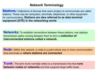
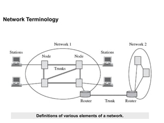
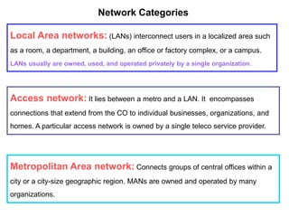
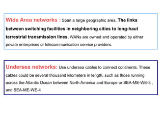
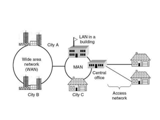
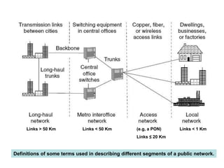
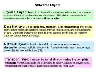
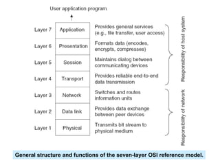
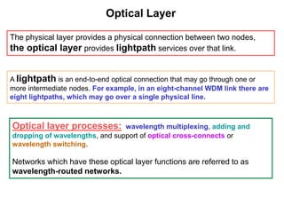
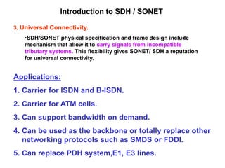
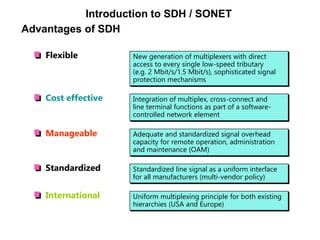
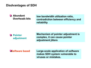
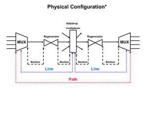
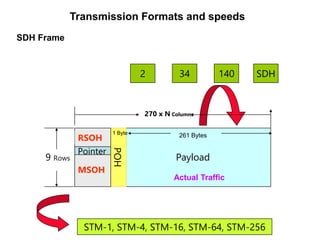
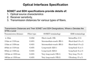
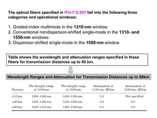
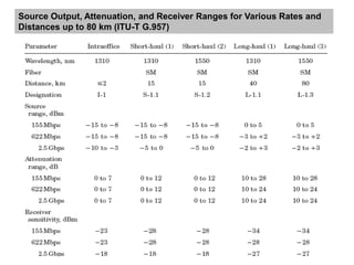
OPTICAL
NETWORKS
1.Network Concepts
2.SDH/ SONET*
3.High Speed Lightwave links
Topics
Network Concepts
1.Network Terminology
2.Network Categories
3.Network Layers
4.Optical Layer
Network Terminology
Stations: Collections of devices that users employ to communicate are called
stations. These may be computers, terminals, telephones, or other equipment
for communicating. Stations are also referred to as data terminal
equipment (DTE) in the networking world.
Networks: To establish connections between these stations, one deploys
transmission paths running between them to form a collection of
interconnected stations called a network.
Node: Within this network, a node is a point where one or more communication
lines terminate or where stations are connected.
Trunk: The term trunk normally refers to a transmission line that runs
between nodes or networks and that supports large traffic loads.
Switching and routing: The transfer of information from source to
destination through a series of intermediate nodes is called switching, and the
selection of a suitable path through a network is referred to as routing.
Router: When two networks that use different information-exchange rules
(protocols) are interconnected, a device called a router is used at the
interconnection point to translate the control information from one
protocol to another.
Topology: The topology is the logical manner in which nodes are
linked together by information transmission channels to form a network.
Network Terminology
Definitions of various elements of a network.
Metropolitan Area network: Connects groups of central offices within a
city or a city-size geographic region. MANs are owned and operated by many
organizations.
Access network: It lies between a metro and a LAN. It encompasses
connections that extend from the CO to individual businesses, organizations, and
homes. A particular access network is owned by a single teleco service provider.
Network Categories
Local Area networks: (LANs) interconnect users in a localized area such
as a room, a department, a building, an office or factory complex, or a campus.
LANs usually are owned, used, and operated privately by a single organization.
Undersea networks: Use undersea cables to connect continents. These
cables could be several thousand kilometers in length, such as those running
across the Atlantic Ocean between North America and Europe or SEA-ME-WE-3 ,
and SEA-ME-WE-4
Wide Area networks : Span a large geographic area. The links
between switching facilities in neighboring cities to long-haul
terrestrial transmission lines. WANs are owned and operated by either
private enterprises or telecommunication service providers.
Enterprise and Public Networks
Enterprise Network: A private organization (for example, a company, a
government entity, a medical facility, a university ) owns and operates a network.
Public Network: Networks that are owned by the telecommunications
carriers provide services such as leased lines or real time telephone
connections to the genera public.
Central office: A communication switching facility in a public network is
calleda central office (CO) or a point of presence (POP).
Long-haul network: A long-haul network interconnects various
cities or geographical regions and spans hundreds to thousands of
kilometers between central offices.
Passive Optical Network: Optical distribution networks that do not
require any active optoelectronic components in the access region offer a
number of operating advantages over the other media. This implementation is
called passive optical networks (PON) and is the basis for the fiber to the
premises networks.
Backbone network: The term backbone describes a high-capacity
network that connects multiple LAN, MAN, or WAN segments. Thus, a
backbone handles internetwork traffic.
Links < 1 Km
(e.g, a PON)
Links ≤ 20 Km
Links < 50 Km
Links > 50 Km
Definitions of some terms used in describing different segments of a public network.
Architecture of a typical passive optical network.
Networks Layers
Physical Layer: Refers to a physical transmission medium, such as a wire or
an optical fiber, that can handle a certain amount of bandwidth. responsible for
actual transmission of bits across a fiber or wire.
Data link layer: It establishes, maintain, and release links that directly
connect two nodes. Its functions include framing ,multiplexing, and demultiplexing
of data. Dominant protocols are point-to-point protocol (PPP) and the highlevel
data link control (HDLC) protocol.
Network layer: Its function is to deliver packets from source to
destination across multiple network links. Currently the dominant network layer
protocol is the Internet Protocol (IP).
Transport layer: is responsible for reliably delivering the complete
message from the source to the destination to satisfy a quality of service (QoS)
requested by the upper layer. Dominant protocols TCP and UDP
General structure and functions of the seven-layer OSI reference model.
Optical Layer
The physical layer provides a physical connection between two nodes,
the optical layer provides lightpath services over that link.
A lightpath is an end-to-end optical connection that may go through one or
more intermediate nodes. For example, in an eight-channel WDM link there are
eight lightpaths, which may go over a single physical line.
Optical layer processes: wavelength multiplexing, adding and
dropping of wavelengths, and support of optical cross-connects or
wavelength switching.
Networks which have these optical layer functions are referred to as
wavelength-routed networks.
The optical layer is a wavelength-based concept and lies just above the
physical layer.
The optical layer carries out processes such as multiplexing, adding/dropping of
wavelengths, and support of optical cross-connects or wavelength switching.
Intentionally Left Blank
SDH / SONET
1. Introduction to SDH/ SONET
• Applications / advantages/ disadvantages
2. Physical Configuration
3. SONET/ SDH Layers
4. Transmission Formats and Speed
5. Optical Interfaces Specifications
6. SONET/ SDH Rings
7. SONET/SDH Networks
Introduction to SDH / SONET
ITU-T standards is called the Synchronous Digital Hierarchy (SDH)
ANSI standards is called the Synchronous Optical Network (SONET)
Three Important concerns in designing SONET/ SDH*
1. It is a Synchronous network.
• A single clock is used to handle the timing of transmission and
equipment across the entire network.
• Network wise synchronization adds a level of predictability to the
system.
• This predictability , coupled with powerful frame design, enables
individual channels to be multiplexed, thereby improving speed
and reducing cost.
2. Standardization.
• SDH/SONET contains recommendations for the standardization of
fiber optic transmission system equipment sold by different
manufacturers.
3. Universal Connectivity.
•SDH/SONET physical specification and frame design include
mechanism that allow it to carry signals from incompatible
tributary systems. This flexibility gives SONET/ SDH a reputation
for universal connectivity.
Applications:
1. Carrier for ISDN and B-ISDN.
2. Carrier for ATM cells.
3. Can support bandwidth on demand.
4. Can be used as the backbone or totally replace other
networking protocols such as SMDS or FDDI.
5. Can replace PDH system,E1, E3 lines.
Introduction to SDH / SONET
Advantages of SDH
Flexible
Cost effective
Manageable
Standardized
International
New generation of multiplexers with direct
access to every single low-speed tributary
(e.g. 2 Mbit/s/1.5 Mbit/s), sophisticated signal
protection mechanisms
Integration of multiplex, cross-connect and
line terminal functions as part of a software-
controlled network element
Adequate and standardized signal overhead
capacity for remote operation, administration
and maintenance (OAM)
Standardized line signal as a uniform interface
for all manufacturers (multi-vendor policy)
Uniform multiplexing principle for both existing
hierarchies (USA and Europe)
Introduction to SDH / SONET
Disdvantages of SDH
Abundant
Overheads bits
low bandwidth utilization ratio,
contradiction between efficiency and
reliability
Mechanism of pointer adjustment is
complex, it can cause pointer
adjustment jitters
Software based Large-scale application of software
makes SDH system vulnerable to
viruses or mistakes.
Pointer
adjustment
Physical Configuration*
MUX MUX
Add/drop
multiplexer
Regenerator Regenerator
Section Section Section Section
Line Line
Path
Multiplexer/ Demultiplexer: Multiplexer marks the beginning and end
points of a SDH link. They provide interface between a tributary network and SDH
and either multiplex signals from multiple sources into an STM signal or
demultiplex as STM signal into different destination Signals.
Regenerator: Regenerator extend the length of the links, it takes optical
signal and regenerates. SDH regenerator replaces some of the existing overhead
information with new information. These devices function at the data link layer.
Add/ drop multiplexer: It can add signals coming from different sources
into a given path or remove a desired signal from a path and redirect it without
demultiplexing the entire signal. Instead of relying on timing and bit position
add/drop multiplexer use header information such as addresses and pointers to
identify the individual steams.
Section: It is the optical link connecting two neighbor devices:
•Multiplexer to Multiplexer
•Multiplexer to Regenerator
•Regenerator to Regenerator
Line: It is the portion of the network between two multiplexers:
•STM Multiplexer to add/drop multiplexer
•Two add/drop multiplexers
•Two STM multiplexers
Paths: It is the end to end portion of the network between two STM
multiplexers.
In a simple SDH of two multiplexers linked directly to each other, the
section, line, and path are the same.
SONET/SDH Layers
Path layer
Section layer
Line layer
Photonic layer
Data link
Physical
SONET/SDH Layers
Photonic Layer: Corresponds to the physical layer of the OSI model. It
includes physical specifications for the optical fiber channel, the sensitivity of the
receiver, multiplexing functions, and so on. It uses NRZ encoding.
Section Layer: It is responsible for the movement of a signal across a
physical section. It handles framing, scrambling and error control. Section layer
overhead is added to the frame at this layer.
Line Layer: It is responsible for the movement of a signal across a
physical line. Line overhead (Pointers, protection bytes, parity bytes etc) is
added to the frame at this layers. STM multiplexer and add/drop multiplexers
provide line layer functions.
Path Layer: It is responsible for the movement of a signal from its optical
source to its optical destination. At the optical source, the signal is changed
from an electronic form into an optical form, multiplexed with other signals, and
encapsulated in a frame. Path layer overhead is added at this layer. STM
multiplexer provide path layer functions.
Device Layer Relationship
MUX MUX
Add/drop
multiplexer
Regenerator Regenerator
Path
Section
Line
Photonic
Path
Section
Line
Photonic
Section
Line
Photonic
Section
Photonic
Section
Photonic
Commonly Used SONET and SDH Transmission Rates
Transmission Formats and speeds
QUIZ:
No of E1s in STM-1,STM-4,STM-16 and STM-64 ?
Line rate calculation
9
270
Total Frame Capacity: 270 X 9 = 2430 Bytes
Total Number of Bits = 2430 X 8 = 19440 Bits
Time Period of One Frame = 125 microseconds
Bits/Second = 19440/125 X 10 -6 = 155.52 Mbits/Sec
= STM-1
4X STM-1 = STM-4
4XSTM-4 = STM-16
Transmission Formats and speeds
SDH components
 SDH Frame is made of the following
– SDH payload
– Pointer
– Path Over head
– Section Overhead
» Multiplex section overhead
» Regenerator section overhead
Overhead is fixed and is like a
Header. It contains all
information including
Monitoring,O&M functions etc.
Transmission Formats and seeds
SDH Frame
SDH
2 34 140
STM-1, STM-4, STM-16, STM-64, STM-256
270 x N Columns
POH
MSOH
Pointer
Payload
RSOH
9 Rows
Actual Traffic
261 Bytes
1 Byte
Transmission Formats and speeds
Optical Interfaces Specification
SONET and SDH specifications provide details of:
1. Optical source characteristics
2. Receiver sensitivity,
3. Transmission distances for various types of fibers.
Transmission Distances and Their SONET and SDH Designations, Where x Denotes the
STM-x Level
Wavelength Ranges and Attenuation for Transmission Distances up to 80km
The optical fibers specified in ITU-T G.957 fall into the following three
categories and operational windows:
1. Graded-index multimode in the 1310-nm window.
2. Conventional nondispersion-shifted single-mode in the 1310- and
1550-nm windows
3. Dispersion-shifted single-mode in the 1550-nm window
Table shows the wavelength and attenuation ranges specified in these
fibers for transmission distances up to 80 km.
Source Output, Attenuation, and Receiver Ranges for Various Rates and
Distances up to 80 km (ITU-T G.957)
SONET/ SDH Rings
•SONET and SDH are configured as either ring or mesh architecture.
•So Loop diversity is achieved in case of link or equipment failure.
•SONET/SDH rings are commonly called self-healing rings. Means
automatic switching to standby link on failure or degradation of the link.
Three main features of SONET/SDH rings:
1. There can be either two or four fibers running between the nodes on a
ring.
2. Operating signal signals can travel either clockwise only (unidirectional
ring) or in both directions around the ring (which is called bidirectional
ring).
3. Protection switching can be performed either via line-switching or a path
switching scheme.
• Line switching moves all signal channels of an entire STM-N
channel to a protection fiber.
• Path switching can move individual payload channels within a
STM-N channel to another path.
SONET/ SDH Rings
Following two architectures have become popular for SONET and
SDH Networks:
1. Two fibers, unidirectional, path-switched ring (two-
fiber UPSR)
2. Two fiber or four fiber, bidirectional, line switched
ring( two fiber or four fiber BLSR)
(They are also referred to as unidirectional or
bidirectional self healing ring , USHRs or BSHRs)
SONET/ SDH Rings
Generic two fiber
unidirectional path-switched
ring (UPSR) with counter
rotating protection path.
Flow of primary and protection
traffic from node 1 to node 3
Architecture of a four-fiber bidirectional line-switched ring (BLSR).
SONET/ SDH Rings
Reconfiguration of a four-fiber BLSR under transceiver or line failure.
SONET/ SDH Rings
SONET /SDH Networks
SONET/SDH equipment allows the configuration of a variety of network
architectures, as shown in next slide. For example
•Point-to-point links
•Linear chains
•UPSRs
•BLSRs
•Interconnected rings
Each of the individual rings has its own failure recovery mechanisms and
SONET/SDH network management procedures.
An important SONET/SDH network element is the add/drop multiplexer
(ADM). This piece of equipment is a fully synchronous, byte-oriented
multiplexer that is used to add and drop subchannels within an OC-N signal.
The SONET/SDH architectures also can be implemented with multiple
wavelengths. For example, Fig in next slide, will show a dense WDM
deployment on an OC-192 trunk ring for n wavelengths
SONET /SDH Networks
Generic configuration of a large SONET network consisting of linear
chains and various types of interconnected rings.
Where
OC-3 = STM-1
OC-12 = STM-4
OC-48 = STM-16
OC-192= STM-64
Functional concept of an add/drop multiplexer for SONET/SDH applications.
SONET /SDH Networks
SONET /SDH Networks
Dense WDM deployment of n wavelengths in an OC-192/ STM-64 trunk ring.
Mapping
 Is the procedure through which signals are packed
inside an SDH frame
 PDH signal passes through the following steps
before emerging as an SDH Signal
 Container (C-X)
 Virtual Container (VC-X)
 Tributary Unit (TU-X)
 Tributary Unit Group (TUG-X)
 Administrative Unit (AU-4)
 STM Signal
How 2 Mb signals are mapped
into an SDH stream?
C-12
VC-12
2 Mb/Sec
Container
Virtual Container
Path Overhead (POH)
How 2 Mb signals are mapped
into an SDH stream?
VC-12
STM-1/4/16
Payload
Pointer
SOH
SOH
270
9
TU
(Tributary Unit)
Starting address of
Payload in VC.
Formation of Synchronous Signal
Pointer
Phase relation between
virtual container (payload)
and subordinate frame
Plesiochronous signal
Path overhead
Additional information for
end-to-end monitoring
Tributary
unit (TU)
Virtual
container
(VC)
Container
(C)
Synchronous Signal
VC11
ITU-T recommendation G.707 and its
realization
× n
× 1
× 3
× 7
× 1
C2
C11
× 3
VC12
× 1
VC4
VC3
C3
VC2
VC
3
C12
TU12
TU2
TU3
TUG3
TUG2
140 Mbit/s
34 Mbit/s
(45 Mbit/s)
(6 Mbit/s)
2 Mbit/s
(1.5 Mbit/s)
AU4
STM-N
AU3
TU11
C4
AUG
Source: TR BM TP 5
AU/G Administrative unit/group
C Container
STM Synchronous transport module
TU/G Tributary unit/group
VC Virtual container
Pointer processing
Multiplexing
Aligning
Mapping
Cross-connect level
SDH Overheads
• An overhead is like a delivery notice with the parcel
which contains information about the contents,
Condition, type, address, postal date, weight etc. of the
parcel.
• In the SDH a distinction is made between Section
Overhead (SOH) and Path Overhead (POH)
SOH
SOH
POH
STM-1
VC-4
SDH Multiplexing Structure
STM-1 AU-4
TU-3
AUG-1
TUG-3 VC-3 C-3
VC-4 C-4
TU-12 VC-12 C-12
TUG-2
×1 ×1
×3
×1
×7
×3
139264 kbit/s
34368 kbit/s
2048 kbit/s
Pointer processing
Multiplexing
Mapping
Aligning
AUG-4
AUG-16
AUG-64
STM-4
STM-16
STM-64
×1
×1
×1
×4
×4
×4
Intentionally Left Blank
High Speed Lightwave Links
1.Links operating at 10 Gb/s
2.Links operating at 40 Gb/s
3.Links operating at 160 Gb/s
High Speed Lightwave Links
A challenge to creating efficient and reliable optical networks for ever
growing demand of bandwidth is the:
Development of high speed optical fiber
transceivers
•Small form factor pluggable (SFP) transceiver can be used for DWDM.
•Such devices have hot-pluggable capability.
•Such transceivers operating at 2.5 Gb/s for DWDM applications with 100 GHz
wavelength spacing are in wide use.
•Laser diodes can be modulated dirrectly up to 2.5 Gb/s (in some cases
up to 10 Gb/s), but usually need an external modulator beyond that point.
•Therefore new challenges emerge for transceivers operating at higher
rates, such as 10, 40, and 160 Gb/s
Links Operating at 10 Gb/s
10-Gb/s Optical fiber transmission system installed worldwide are:
1. Fibre channel connections for storage area network.
2. 10- gigabit Ethernet lines for local area and metro networks.
3. SONET/SDH OC192/STM64 terrestrial and undersea long haul lines .
•Wide selection of industry standardized transceiver packages are available for
these applications.
•Several multimode fibers with different bandwidth grades exists for 10 Gb/s.
Fiber class and
size
BW@850nm
(MHz-Km)
BW@1300nm
(MHz-Km)
Max distance
for 1 Gb/s
@850 nm
Max distance
for 1 Gb/s
@1300 nm
Max distance
for 10 Gb/s
@850 nm
OM1 62.5/125 200 500 300 m 550 m 33m
OM2 50/125 500 800 750 m 200 m 82 m
OM3 50/125 2000 500 950 m 600 m 300 m
Extended reach
(ER)
3500 500 1040 m 600 m 550 m
Multimode fiber classification and their use with 1 and 10 Gb/s Ehernet
Links Operating at 10 Gb/s
For short-reach 10-Gb/s network: All segment of the network should use the
same grade of multimode fiber.
But in some cases segment can contain spliced OM2 and OM3 fibers.
For OM2 and OM3 fibers spliced together: then bandwidths of the fibers will
determine the resulting effective maximum link length.
Lmax =LOM2 (BW OM3/ BW OM2) + LOM3 (OM2 and OM3 having same geometric parameters)
Max link length calculated by this equation must be less than the
achievable link length if only OM3 fiber is used.
Q: An engineer wants to create a link consisting of 40 m of OM2 fiber that
has a 500 MHz bandwidth and 100 m of OM3 fiber that has a 2000 MHz
bandwidth. Calculate the maximum link length ?
Lmax=?
Where LOM2= 40 m LOM3= 100 m
BWOM3=2000 MHz BWOM2= 500 MHz
Links Operating at 10 Gb/s
For a acces network application ranging from 7 to 20 km:
The 10-GbE specificaton calls Long Reach (LR).
The link needs to use InGaAsP bassed distributed feedback (DFB) lasers.
These links operate near the 1310 nm dispersion minimum of G.652 single
mode fibers and the light sources can be modulated directly.
For metro network application ranging from 40 to 80 km
The 10-GbE specification calls extended reach (ER).
The link needs to use externally modulated distributed feedback (DFB)
lasers operating at 1550 nm over single mode fibers.
A number of vendors offer a variety of transceiver packages for both LR and ER
applications. Three of Several configurations include:
1. 300-pin 2. XFP 3.SFP
Links Operating at 40 Gb/s
New Challenges at 40 Gb/s data rate, in terms of:
1. Transceiver response characteristics
2. Chromatic dispersion control
3. Polarization mode dispersion compensation
Compared to 10-Gb/s system, Link operating at 40 Gb/s and using
conventional OOK modulation format, is:
1. sixteen times more sensitive to chromatic dispersion.
2. Four times more sensitive to polarization mode dispersion
3. Optical signal to noise ratio (OSNR) which is at least 6 dB higer is
required to reach an equivalent bit error rate (BER)
Therefore alternate modulation scheme are considered.
One method is Binary differential phase shift keying or simply DPSK.
The most widely accept format has been RZ-DPSK for which transceiver
modules that can interface to SONET-678/SDH -256 equipment are
available.
OTDM Links Operating at 160 Gb/s
160 Gb/s over a single wavelength using G.652 single
mode fiber are tested.
These test link used the concept of OPTICAL TIME
DIVISION MULTIPLEXING (OTDM) to form 160 Gb/s data
stream, since electronic devices that are needed for
carrying out signal processing at these rates were not
available.
One option is to use bit-interleaved OTDM.
Time multiplexed media rate can be up to 160 Gb/s
Several field trials have demonstrated the feasibility of long haul 160
Gb/s transmission systems.
Interesting point to note about these 160 Gb/s experiments is that
good performance was obtained using installed standard G.652
single mode fiber.
Example of an ultra-fast point to point transmission system using optical
TDM.
Basic concept of point to point transmission using bit interveaved
optical TDM
A B C D A B C D
Modulator
A B C D
Modulator
Modulator
Modulator
10 GHz
Optical
Pulse
Source
10 Gb/s Pulse stream
Four 10 Gb/s
Data sources:
Fiber
delay
lines
Signal stream
EDFA EDFA
Postamplifier Preamplifier
Demultiplexer
Clock
recovery
10 GHz Clock
Receiver
Receiver
Receiver
Receiver
A
B
C
D
Optical
splitter
OTDM Links Operating at 160 Gb/s
GERMANY:
Researchers achieved repeaterless error free transmission.
1 x 170 Gb/s signals over 185 Km
8 x 170 Gb/s signals (eight WDM signals) over 140 Km
On Single mode fiber using RZ-DPSK modulation.
170 Gb/s signal was created by time interleaving four channels operation at 42.7 Gb/s
JAPAN:
To cope with transmission impairments from CD and PMD.
Researchers investigated the use of 2-bit/symbol encoding techniques such as differential quadrature
phase shift keying (DQPSK) and simultaneous amplitude shift keying (ASK) and DPSK.
160 Gb/s signal was composed of eight 20 Gb/s channels
Relatively stable BER charactersitics were obtained after transmission over 200 Km of installed G.652 single
mode fiver.
UNITED KINGDOM:
160 Gb/s experiment carried out by the researchers.
The impact of chromatic and polarization mode dispersion were examined on 275 and 550 km links of
installed SSMF.
The 160 Gb/s signal was created by time interleaving sixteen channels operating at 10 Gb/s each.
Experiments showed excellent operation of clock recovery, BER, and functions of dropping and adding
wavelength channels.

1536997963_ch2 optical network details...

  • 1.
  • 2.
    1.Network Concepts 2.SDH/ SONET* 3.HighSpeed Lightwave links Topics
  • 3.
    Network Concepts 1.Network Terminology 2.NetworkCategories 3.Network Layers 4.Optical Layer
  • 4.
    Network Terminology Stations: Collectionsof devices that users employ to communicate are called stations. These may be computers, terminals, telephones, or other equipment for communicating. Stations are also referred to as data terminal equipment (DTE) in the networking world. Networks: To establish connections between these stations, one deploys transmission paths running between them to form a collection of interconnected stations called a network. Node: Within this network, a node is a point where one or more communication lines terminate or where stations are connected. Trunk: The term trunk normally refers to a transmission line that runs between nodes or networks and that supports large traffic loads.
  • 5.
    Switching and routing:The transfer of information from source to destination through a series of intermediate nodes is called switching, and the selection of a suitable path through a network is referred to as routing. Router: When two networks that use different information-exchange rules (protocols) are interconnected, a device called a router is used at the interconnection point to translate the control information from one protocol to another. Topology: The topology is the logical manner in which nodes are linked together by information transmission channels to form a network.
  • 6.
    Network Terminology Definitions ofvarious elements of a network.
  • 7.
    Metropolitan Area network:Connects groups of central offices within a city or a city-size geographic region. MANs are owned and operated by many organizations. Access network: It lies between a metro and a LAN. It encompasses connections that extend from the CO to individual businesses, organizations, and homes. A particular access network is owned by a single teleco service provider. Network Categories Local Area networks: (LANs) interconnect users in a localized area such as a room, a department, a building, an office or factory complex, or a campus. LANs usually are owned, used, and operated privately by a single organization.
  • 8.
    Undersea networks: Useundersea cables to connect continents. These cables could be several thousand kilometers in length, such as those running across the Atlantic Ocean between North America and Europe or SEA-ME-WE-3 , and SEA-ME-WE-4 Wide Area networks : Span a large geographic area. The links between switching facilities in neighboring cities to long-haul terrestrial transmission lines. WANs are owned and operated by either private enterprises or telecommunication service providers.
  • 10.
    Enterprise and PublicNetworks Enterprise Network: A private organization (for example, a company, a government entity, a medical facility, a university ) owns and operates a network. Public Network: Networks that are owned by the telecommunications carriers provide services such as leased lines or real time telephone connections to the genera public. Central office: A communication switching facility in a public network is calleda central office (CO) or a point of presence (POP).
  • 11.
    Long-haul network: Along-haul network interconnects various cities or geographical regions and spans hundreds to thousands of kilometers between central offices. Passive Optical Network: Optical distribution networks that do not require any active optoelectronic components in the access region offer a number of operating advantages over the other media. This implementation is called passive optical networks (PON) and is the basis for the fiber to the premises networks. Backbone network: The term backbone describes a high-capacity network that connects multiple LAN, MAN, or WAN segments. Thus, a backbone handles internetwork traffic.
  • 12.
    Links < 1Km (e.g, a PON) Links ≤ 20 Km Links < 50 Km Links > 50 Km Definitions of some terms used in describing different segments of a public network.
  • 13.
    Architecture of atypical passive optical network.
  • 14.
    Networks Layers Physical Layer:Refers to a physical transmission medium, such as a wire or an optical fiber, that can handle a certain amount of bandwidth. responsible for actual transmission of bits across a fiber or wire. Data link layer: It establishes, maintain, and release links that directly connect two nodes. Its functions include framing ,multiplexing, and demultiplexing of data. Dominant protocols are point-to-point protocol (PPP) and the highlevel data link control (HDLC) protocol. Network layer: Its function is to deliver packets from source to destination across multiple network links. Currently the dominant network layer protocol is the Internet Protocol (IP). Transport layer: is responsible for reliably delivering the complete message from the source to the destination to satisfy a quality of service (QoS) requested by the upper layer. Dominant protocols TCP and UDP
  • 15.
    General structure andfunctions of the seven-layer OSI reference model.
  • 16.
    Optical Layer The physicallayer provides a physical connection between two nodes, the optical layer provides lightpath services over that link. A lightpath is an end-to-end optical connection that may go through one or more intermediate nodes. For example, in an eight-channel WDM link there are eight lightpaths, which may go over a single physical line. Optical layer processes: wavelength multiplexing, adding and dropping of wavelengths, and support of optical cross-connects or wavelength switching. Networks which have these optical layer functions are referred to as wavelength-routed networks.
  • 17.
    The optical layeris a wavelength-based concept and lies just above the physical layer.
  • 18.
    The optical layercarries out processes such as multiplexing, adding/dropping of wavelengths, and support of optical cross-connects or wavelength switching.
  • 19.
  • 20.
    SDH / SONET 1.Introduction to SDH/ SONET • Applications / advantages/ disadvantages 2. Physical Configuration 3. SONET/ SDH Layers 4. Transmission Formats and Speed 5. Optical Interfaces Specifications 6. SONET/ SDH Rings 7. SONET/SDH Networks
  • 21.
    Introduction to SDH/ SONET ITU-T standards is called the Synchronous Digital Hierarchy (SDH) ANSI standards is called the Synchronous Optical Network (SONET) Three Important concerns in designing SONET/ SDH* 1. It is a Synchronous network. • A single clock is used to handle the timing of transmission and equipment across the entire network. • Network wise synchronization adds a level of predictability to the system. • This predictability , coupled with powerful frame design, enables individual channels to be multiplexed, thereby improving speed and reducing cost. 2. Standardization. • SDH/SONET contains recommendations for the standardization of fiber optic transmission system equipment sold by different manufacturers.
  • 22.
    3. Universal Connectivity. •SDH/SONETphysical specification and frame design include mechanism that allow it to carry signals from incompatible tributary systems. This flexibility gives SONET/ SDH a reputation for universal connectivity. Applications: 1. Carrier for ISDN and B-ISDN. 2. Carrier for ATM cells. 3. Can support bandwidth on demand. 4. Can be used as the backbone or totally replace other networking protocols such as SMDS or FDDI. 5. Can replace PDH system,E1, E3 lines. Introduction to SDH / SONET
  • 23.
    Advantages of SDH Flexible Costeffective Manageable Standardized International New generation of multiplexers with direct access to every single low-speed tributary (e.g. 2 Mbit/s/1.5 Mbit/s), sophisticated signal protection mechanisms Integration of multiplex, cross-connect and line terminal functions as part of a software- controlled network element Adequate and standardized signal overhead capacity for remote operation, administration and maintenance (OAM) Standardized line signal as a uniform interface for all manufacturers (multi-vendor policy) Uniform multiplexing principle for both existing hierarchies (USA and Europe) Introduction to SDH / SONET
  • 24.
    Disdvantages of SDH Abundant Overheadsbits low bandwidth utilization ratio, contradiction between efficiency and reliability Mechanism of pointer adjustment is complex, it can cause pointer adjustment jitters Software based Large-scale application of software makes SDH system vulnerable to viruses or mistakes. Pointer adjustment
  • 25.
    Physical Configuration* MUX MUX Add/drop multiplexer RegeneratorRegenerator Section Section Section Section Line Line Path
  • 26.
    Multiplexer/ Demultiplexer: Multiplexermarks the beginning and end points of a SDH link. They provide interface between a tributary network and SDH and either multiplex signals from multiple sources into an STM signal or demultiplex as STM signal into different destination Signals. Regenerator: Regenerator extend the length of the links, it takes optical signal and regenerates. SDH regenerator replaces some of the existing overhead information with new information. These devices function at the data link layer. Add/ drop multiplexer: It can add signals coming from different sources into a given path or remove a desired signal from a path and redirect it without demultiplexing the entire signal. Instead of relying on timing and bit position add/drop multiplexer use header information such as addresses and pointers to identify the individual steams.
  • 27.
    Section: It isthe optical link connecting two neighbor devices: •Multiplexer to Multiplexer •Multiplexer to Regenerator •Regenerator to Regenerator Line: It is the portion of the network between two multiplexers: •STM Multiplexer to add/drop multiplexer •Two add/drop multiplexers •Two STM multiplexers Paths: It is the end to end portion of the network between two STM multiplexers. In a simple SDH of two multiplexers linked directly to each other, the section, line, and path are the same.
  • 28.
    SONET/SDH Layers Path layer Sectionlayer Line layer Photonic layer Data link Physical
  • 29.
    SONET/SDH Layers Photonic Layer:Corresponds to the physical layer of the OSI model. It includes physical specifications for the optical fiber channel, the sensitivity of the receiver, multiplexing functions, and so on. It uses NRZ encoding. Section Layer: It is responsible for the movement of a signal across a physical section. It handles framing, scrambling and error control. Section layer overhead is added to the frame at this layer. Line Layer: It is responsible for the movement of a signal across a physical line. Line overhead (Pointers, protection bytes, parity bytes etc) is added to the frame at this layers. STM multiplexer and add/drop multiplexers provide line layer functions. Path Layer: It is responsible for the movement of a signal from its optical source to its optical destination. At the optical source, the signal is changed from an electronic form into an optical form, multiplexed with other signals, and encapsulated in a frame. Path layer overhead is added at this layer. STM multiplexer provide path layer functions.
  • 30.
    Device Layer Relationship MUXMUX Add/drop multiplexer Regenerator Regenerator Path Section Line Photonic Path Section Line Photonic Section Line Photonic Section Photonic Section Photonic
  • 31.
    Commonly Used SONETand SDH Transmission Rates Transmission Formats and speeds QUIZ: No of E1s in STM-1,STM-4,STM-16 and STM-64 ?
  • 32.
    Line rate calculation 9 270 TotalFrame Capacity: 270 X 9 = 2430 Bytes Total Number of Bits = 2430 X 8 = 19440 Bits Time Period of One Frame = 125 microseconds Bits/Second = 19440/125 X 10 -6 = 155.52 Mbits/Sec = STM-1 4X STM-1 = STM-4 4XSTM-4 = STM-16 Transmission Formats and speeds
  • 33.
    SDH components  SDHFrame is made of the following – SDH payload – Pointer – Path Over head – Section Overhead » Multiplex section overhead » Regenerator section overhead Overhead is fixed and is like a Header. It contains all information including Monitoring,O&M functions etc. Transmission Formats and seeds
  • 34.
    SDH Frame SDH 2 34140 STM-1, STM-4, STM-16, STM-64, STM-256 270 x N Columns POH MSOH Pointer Payload RSOH 9 Rows Actual Traffic 261 Bytes 1 Byte Transmission Formats and speeds
  • 35.
    Optical Interfaces Specification SONETand SDH specifications provide details of: 1. Optical source characteristics 2. Receiver sensitivity, 3. Transmission distances for various types of fibers. Transmission Distances and Their SONET and SDH Designations, Where x Denotes the STM-x Level
  • 36.
    Wavelength Ranges andAttenuation for Transmission Distances up to 80km The optical fibers specified in ITU-T G.957 fall into the following three categories and operational windows: 1. Graded-index multimode in the 1310-nm window. 2. Conventional nondispersion-shifted single-mode in the 1310- and 1550-nm windows 3. Dispersion-shifted single-mode in the 1550-nm window Table shows the wavelength and attenuation ranges specified in these fibers for transmission distances up to 80 km.
  • 37.
    Source Output, Attenuation,and Receiver Ranges for Various Rates and Distances up to 80 km (ITU-T G.957)
  • 38.
    SONET/ SDH Rings •SONETand SDH are configured as either ring or mesh architecture. •So Loop diversity is achieved in case of link or equipment failure. •SONET/SDH rings are commonly called self-healing rings. Means automatic switching to standby link on failure or degradation of the link. Three main features of SONET/SDH rings: 1. There can be either two or four fibers running between the nodes on a ring. 2. Operating signal signals can travel either clockwise only (unidirectional ring) or in both directions around the ring (which is called bidirectional ring). 3. Protection switching can be performed either via line-switching or a path switching scheme. • Line switching moves all signal channels of an entire STM-N channel to a protection fiber. • Path switching can move individual payload channels within a STM-N channel to another path.
  • 39.
    SONET/ SDH Rings Followingtwo architectures have become popular for SONET and SDH Networks: 1. Two fibers, unidirectional, path-switched ring (two- fiber UPSR) 2. Two fiber or four fiber, bidirectional, line switched ring( two fiber or four fiber BLSR) (They are also referred to as unidirectional or bidirectional self healing ring , USHRs or BSHRs)
  • 40.
    SONET/ SDH Rings Generictwo fiber unidirectional path-switched ring (UPSR) with counter rotating protection path. Flow of primary and protection traffic from node 1 to node 3
  • 41.
    Architecture of afour-fiber bidirectional line-switched ring (BLSR). SONET/ SDH Rings
  • 42.
    Reconfiguration of afour-fiber BLSR under transceiver or line failure. SONET/ SDH Rings
  • 43.
    SONET /SDH Networks SONET/SDHequipment allows the configuration of a variety of network architectures, as shown in next slide. For example •Point-to-point links •Linear chains •UPSRs •BLSRs •Interconnected rings Each of the individual rings has its own failure recovery mechanisms and SONET/SDH network management procedures. An important SONET/SDH network element is the add/drop multiplexer (ADM). This piece of equipment is a fully synchronous, byte-oriented multiplexer that is used to add and drop subchannels within an OC-N signal. The SONET/SDH architectures also can be implemented with multiple wavelengths. For example, Fig in next slide, will show a dense WDM deployment on an OC-192 trunk ring for n wavelengths
  • 44.
    SONET /SDH Networks Genericconfiguration of a large SONET network consisting of linear chains and various types of interconnected rings. Where OC-3 = STM-1 OC-12 = STM-4 OC-48 = STM-16 OC-192= STM-64
  • 45.
    Functional concept ofan add/drop multiplexer for SONET/SDH applications. SONET /SDH Networks
  • 46.
    SONET /SDH Networks DenseWDM deployment of n wavelengths in an OC-192/ STM-64 trunk ring.
  • 47.
    Mapping  Is theprocedure through which signals are packed inside an SDH frame  PDH signal passes through the following steps before emerging as an SDH Signal  Container (C-X)  Virtual Container (VC-X)  Tributary Unit (TU-X)  Tributary Unit Group (TUG-X)  Administrative Unit (AU-4)  STM Signal
  • 48.
    How 2 Mbsignals are mapped into an SDH stream? C-12 VC-12 2 Mb/Sec Container Virtual Container Path Overhead (POH)
  • 49.
    How 2 Mbsignals are mapped into an SDH stream? VC-12 STM-1/4/16 Payload Pointer SOH SOH 270 9 TU (Tributary Unit) Starting address of Payload in VC.
  • 50.
    Formation of SynchronousSignal Pointer Phase relation between virtual container (payload) and subordinate frame Plesiochronous signal Path overhead Additional information for end-to-end monitoring Tributary unit (TU) Virtual container (VC) Container (C) Synchronous Signal
  • 51.
    VC11 ITU-T recommendation G.707and its realization × n × 1 × 3 × 7 × 1 C2 C11 × 3 VC12 × 1 VC4 VC3 C3 VC2 VC 3 C12 TU12 TU2 TU3 TUG3 TUG2 140 Mbit/s 34 Mbit/s (45 Mbit/s) (6 Mbit/s) 2 Mbit/s (1.5 Mbit/s) AU4 STM-N AU3 TU11 C4 AUG Source: TR BM TP 5 AU/G Administrative unit/group C Container STM Synchronous transport module TU/G Tributary unit/group VC Virtual container Pointer processing Multiplexing Aligning Mapping Cross-connect level
  • 52.
    SDH Overheads • Anoverhead is like a delivery notice with the parcel which contains information about the contents, Condition, type, address, postal date, weight etc. of the parcel. • In the SDH a distinction is made between Section Overhead (SOH) and Path Overhead (POH) SOH SOH POH STM-1 VC-4
  • 53.
    SDH Multiplexing Structure STM-1AU-4 TU-3 AUG-1 TUG-3 VC-3 C-3 VC-4 C-4 TU-12 VC-12 C-12 TUG-2 ×1 ×1 ×3 ×1 ×7 ×3 139264 kbit/s 34368 kbit/s 2048 kbit/s Pointer processing Multiplexing Mapping Aligning AUG-4 AUG-16 AUG-64 STM-4 STM-16 STM-64 ×1 ×1 ×1 ×4 ×4 ×4
  • 54.
  • 55.
    High Speed LightwaveLinks 1.Links operating at 10 Gb/s 2.Links operating at 40 Gb/s 3.Links operating at 160 Gb/s
  • 56.
    High Speed LightwaveLinks A challenge to creating efficient and reliable optical networks for ever growing demand of bandwidth is the: Development of high speed optical fiber transceivers •Small form factor pluggable (SFP) transceiver can be used for DWDM. •Such devices have hot-pluggable capability. •Such transceivers operating at 2.5 Gb/s for DWDM applications with 100 GHz wavelength spacing are in wide use. •Laser diodes can be modulated dirrectly up to 2.5 Gb/s (in some cases up to 10 Gb/s), but usually need an external modulator beyond that point. •Therefore new challenges emerge for transceivers operating at higher rates, such as 10, 40, and 160 Gb/s
  • 57.
    Links Operating at10 Gb/s 10-Gb/s Optical fiber transmission system installed worldwide are: 1. Fibre channel connections for storage area network. 2. 10- gigabit Ethernet lines for local area and metro networks. 3. SONET/SDH OC192/STM64 terrestrial and undersea long haul lines . •Wide selection of industry standardized transceiver packages are available for these applications. •Several multimode fibers with different bandwidth grades exists for 10 Gb/s. Fiber class and size BW@850nm (MHz-Km) BW@1300nm (MHz-Km) Max distance for 1 Gb/s @850 nm Max distance for 1 Gb/s @1300 nm Max distance for 10 Gb/s @850 nm OM1 62.5/125 200 500 300 m 550 m 33m OM2 50/125 500 800 750 m 200 m 82 m OM3 50/125 2000 500 950 m 600 m 300 m Extended reach (ER) 3500 500 1040 m 600 m 550 m Multimode fiber classification and their use with 1 and 10 Gb/s Ehernet
  • 58.
    Links Operating at10 Gb/s For short-reach 10-Gb/s network: All segment of the network should use the same grade of multimode fiber. But in some cases segment can contain spliced OM2 and OM3 fibers. For OM2 and OM3 fibers spliced together: then bandwidths of the fibers will determine the resulting effective maximum link length. Lmax =LOM2 (BW OM3/ BW OM2) + LOM3 (OM2 and OM3 having same geometric parameters) Max link length calculated by this equation must be less than the achievable link length if only OM3 fiber is used. Q: An engineer wants to create a link consisting of 40 m of OM2 fiber that has a 500 MHz bandwidth and 100 m of OM3 fiber that has a 2000 MHz bandwidth. Calculate the maximum link length ? Lmax=? Where LOM2= 40 m LOM3= 100 m BWOM3=2000 MHz BWOM2= 500 MHz
  • 59.
    Links Operating at10 Gb/s For a acces network application ranging from 7 to 20 km: The 10-GbE specificaton calls Long Reach (LR). The link needs to use InGaAsP bassed distributed feedback (DFB) lasers. These links operate near the 1310 nm dispersion minimum of G.652 single mode fibers and the light sources can be modulated directly. For metro network application ranging from 40 to 80 km The 10-GbE specification calls extended reach (ER). The link needs to use externally modulated distributed feedback (DFB) lasers operating at 1550 nm over single mode fibers. A number of vendors offer a variety of transceiver packages for both LR and ER applications. Three of Several configurations include: 1. 300-pin 2. XFP 3.SFP
  • 60.
    Links Operating at40 Gb/s New Challenges at 40 Gb/s data rate, in terms of: 1. Transceiver response characteristics 2. Chromatic dispersion control 3. Polarization mode dispersion compensation Compared to 10-Gb/s system, Link operating at 40 Gb/s and using conventional OOK modulation format, is: 1. sixteen times more sensitive to chromatic dispersion. 2. Four times more sensitive to polarization mode dispersion 3. Optical signal to noise ratio (OSNR) which is at least 6 dB higer is required to reach an equivalent bit error rate (BER) Therefore alternate modulation scheme are considered. One method is Binary differential phase shift keying or simply DPSK. The most widely accept format has been RZ-DPSK for which transceiver modules that can interface to SONET-678/SDH -256 equipment are available.
  • 61.
    OTDM Links Operatingat 160 Gb/s 160 Gb/s over a single wavelength using G.652 single mode fiber are tested. These test link used the concept of OPTICAL TIME DIVISION MULTIPLEXING (OTDM) to form 160 Gb/s data stream, since electronic devices that are needed for carrying out signal processing at these rates were not available. One option is to use bit-interleaved OTDM. Time multiplexed media rate can be up to 160 Gb/s Several field trials have demonstrated the feasibility of long haul 160 Gb/s transmission systems. Interesting point to note about these 160 Gb/s experiments is that good performance was obtained using installed standard G.652 single mode fiber.
  • 62.
    Example of anultra-fast point to point transmission system using optical TDM. Basic concept of point to point transmission using bit interveaved optical TDM A B C D A B C D Modulator A B C D Modulator Modulator Modulator 10 GHz Optical Pulse Source 10 Gb/s Pulse stream Four 10 Gb/s Data sources: Fiber delay lines Signal stream EDFA EDFA Postamplifier Preamplifier Demultiplexer Clock recovery 10 GHz Clock Receiver Receiver Receiver Receiver A B C D Optical splitter
  • 63.
    OTDM Links Operatingat 160 Gb/s GERMANY: Researchers achieved repeaterless error free transmission. 1 x 170 Gb/s signals over 185 Km 8 x 170 Gb/s signals (eight WDM signals) over 140 Km On Single mode fiber using RZ-DPSK modulation. 170 Gb/s signal was created by time interleaving four channels operation at 42.7 Gb/s JAPAN: To cope with transmission impairments from CD and PMD. Researchers investigated the use of 2-bit/symbol encoding techniques such as differential quadrature phase shift keying (DQPSK) and simultaneous amplitude shift keying (ASK) and DPSK. 160 Gb/s signal was composed of eight 20 Gb/s channels Relatively stable BER charactersitics were obtained after transmission over 200 Km of installed G.652 single mode fiver. UNITED KINGDOM: 160 Gb/s experiment carried out by the researchers. The impact of chromatic and polarization mode dispersion were examined on 275 and 550 km links of installed SSMF. The 160 Gb/s signal was created by time interleaving sixteen channels operating at 10 Gb/s each. Experiments showed excellent operation of clock recovery, BER, and functions of dropping and adding wavelength channels.