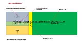
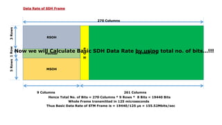
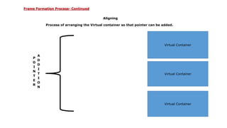
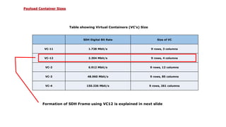
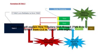
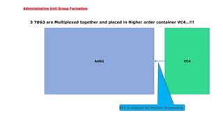
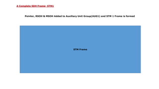
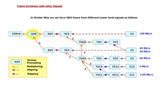
© 2011 Infosys Technologies Limited, India
Infosys
SDH Frame Structure
November, 2011
INFOSYS TECHNOLOGIES LIMITED
Pune
COPYRIGHT NOTICE
© 2011 Infosys Technologies Limited, Bangalore, India. All rights reserved. Infosys believes the
information in this document is accurate as of its publication date; such information is subject to change
without notice. Infosys acknowledges the proprietary rights of other companies to the trademarks,
product names and such other intellectual property rights mentioned in this document. Except as
expressly permitted, neither this document nor any part of it may be reproduced, stored in a retrieval
system, or transmitted in any form or by any means, electronic, mechanical, printing, photocopying,
recording or otherwise, without the prior permission of Infosys Technologies Limited and/or any named
intellectual property rights holders under this document.
Infosys Technologies Limited
Hosur Road
Electronic City, 3rd Cross
Bangalore 560 100
India.
Telephone: (91) (80)28520 261-270
Fax: (91) (80) 8520 362
Website: http://www.infosys.com
© 2011 Infosys Technologies Limited, India
Author(s): Samadhan Ravindra Tambe
Date written (MM/DD/YY): 11/29/11
Project Details: SDH Transmission Related
PPT
What we will come to know after this presentation???
1. What is SDH.
2. Basic Frame structure of SDH.
3. How to calculate Basic Data Rate of SDH Frame using Total No. of Bits.
4. SDH Frame formation processes Mapping, Aligning, Pointer Processing etc.
5. SDH Frame formation using Lower Level Signal (C12).
Points Covered
What is SDH?
SDH Means Synchronous Digital Hierarchy, It is a standard Protocol for transmission of data over a
medium.
It is designed by International Telecommunication Union i.e. ITU and it was deployed on
telecommunication network in the year of 1992.
Main fundamental of SDH is to overly and transmit a Synchronous Multiplexed light stream Signal onto a
Fiber Optic cable.
SDH is bandwidth Flexible and it also allows Multivendor Internetworking. It has numerous advantages
over traditional Transmission technologies such as PDH i.e. Plesiocronous Digital Hierarchy (PDH).
SDH signal is bandwidth Flexible and hence different types of lower order signal can be transmitted in
its Virtual Container.
Introduction to SDH
Basic SDH Signal
The basic transmission format of SDH is a STM-1 Frame which is transmitted in 125 Microseconds time
slot in Byte wise pattern. There are 8000 Frames Transmitted per Second.
In all there are 9 Rows and 270 Columns in a STM Frame, of which first 9 Columns of each frame forms
Sectional Overheads and Pointer.
Remaining 261 Columns consist of Virtual Container (VC) which carries actual data. This VC along with
Pointer Bytes called as Administrative Unit (AU).
As there are 270 Columns, 9 Rows having 8 Bytes total number of bytes in STM-1 Frame will be
270*9=2430 Bytes.
Basic Facts About SDH
RSOH
Pointer
MSOH
Payload(VC)
Regenerator Section Overhead Indicates start of
Payload
Multiplexer Section Overhead
Actual Data
P
O
H
Path Over Head
This Slide will show basic SDH Frame structure…!!!
SDH Frame Structure
RSOH
Pointer
MSOH
Payload(VC)
P
O
H
270 Columns
261 Columns9 Columns
5Rows1Row3Rows
Hence Total No. of Bits = 270 Columns * 9 Rows * 8 Bits = 19440 Bits
Whole Frame transmitted in 125 microseconds
Thus Basic Data Rate of STM Frame is = 19440/125 µs = 155.52Mbits/sec
Now we will Calculate Basic SDH Data Rate by using total no. of bits…!!!
Data Rate of SDH Frame
Mapping
Adding justification bits and Path Overhead to Lower Level Signals so that they can be fit into Virtual
Containers (VC’s)
Vertual Container
Stuffing Bits
Stuffi
ng
Bits
Stuffing Bits
Stuffing Bits
Stuffi
ng
Bits
Stuffing Bits
Data Bits
Frame Formation Process
Aligning
Process of arranging the Virtual container so that pointer can be added.
Virtual Container
Virtual Container
Virtual Container
P
O
I
N
T
E
R
A
D
D
I
T
I
O
N
Frame Formation Process- Continued
Pointer Processing
Process of adding Pointer to Aligned Virtual Containers.
Frame Formation Process- Continued
Multiplexing
Process of combining Same size Units together.
Trib Unit
Trib UnitTrib Unit
Trib Unit
Frame Formation Process- Continued
SDH Digital Bit Rate Size of VC
VC-11 1.728 Mbit/s 9 rows, 3 columns
VC-12 2.304 Mbit/s 9 rows, 4 columns
VC-2 6.912 Mbit/s 9 rows, 12 columns
VC-3 48.960 Mbit/s 9 rows, 85 columns
VC-4 150.336 Mbit/s 9 rows, 261 columns
Table showing Virtual Containers (VC’s) Size
Formation of SDH Frame using VC12 is explained in next slide
Payload Container Sizes
C12VC12TU12
Signal is
mapped into
Container
VC’s are
aligned for
Pointer
Addition
TU12
TU12
TUG2
Pointer Processing
Tributary Units are
Multiplexed
TU12
TU12
TU12
TUG 3
This Slide will explain How Tributary Unit Group3 (TUG 3) is
formed from C12 ie. Lower Level Signal
7 TUG2’s are Multiplex to form TUG3
Formation Of TUG 3
VC4
3 TUG3 are Multiplexed together and placed in Higher order container VC4…!!!
AU4AUG1
VC4 is aligned for Pointer Processing
Administrative Unit Group Formation
Payload
Pointer, RSOH & MSOH Added to Auxiliary Unit Group(AUG1) and STM 1 Frame is formed
POINTER
MSOH
RSOH
H
O
P
O
H
STM Frame
A Complete SDH Frame- STM1
In Similar Way we can form SDH frame from different Lower level signals as follows
AU4
Pointer
Processing
Multiplexing
Aligning
Mapping
STM-N AUG AU4 VC4
TUG3 TU3 VC3
TUG2 TU2 VC2 C2
TU12 VC12 C12
TU11 VC11 C11
C4
AU3 VC3 C3
139 Mb/s
45 Mb/s
34 Mb/s
63 Mb/s
2 Mb/s
1.55 Mb/s
3
3
3
4
7
´7
Frame formation with other Signals
Thank You…!!!
Target readers
Project related Transmission, Fiber and SDH Sonet.
Keywords
SDH, Transmission, SDH Frame, SDH Basic Data Rate
Introduction
SDH Frame structure
Presentation will introduce us to SDH and it’s basic frame structure. It also explain how SDH
frame is formed from lower level signals.
Reference(s):
1. SDH Telecommunications Standard Primer, Tektronix, 2001.
© 2010 Infosys Technologies Limited, India

SDH Frame Structure

  • 1.
    © 2011 InfosysTechnologies Limited, India Infosys SDH Frame Structure November, 2011 INFOSYS TECHNOLOGIES LIMITED Pune
  • 2.
    COPYRIGHT NOTICE © 2011Infosys Technologies Limited, Bangalore, India. All rights reserved. Infosys believes the information in this document is accurate as of its publication date; such information is subject to change without notice. Infosys acknowledges the proprietary rights of other companies to the trademarks, product names and such other intellectual property rights mentioned in this document. Except as expressly permitted, neither this document nor any part of it may be reproduced, stored in a retrieval system, or transmitted in any form or by any means, electronic, mechanical, printing, photocopying, recording or otherwise, without the prior permission of Infosys Technologies Limited and/or any named intellectual property rights holders under this document. Infosys Technologies Limited Hosur Road Electronic City, 3rd Cross Bangalore 560 100 India. Telephone: (91) (80)28520 261-270 Fax: (91) (80) 8520 362 Website: http://www.infosys.com © 2011 Infosys Technologies Limited, India
  • 3.
    Author(s): Samadhan RavindraTambe Date written (MM/DD/YY): 11/29/11 Project Details: SDH Transmission Related PPT
  • 4.
    What we willcome to know after this presentation??? 1. What is SDH. 2. Basic Frame structure of SDH. 3. How to calculate Basic Data Rate of SDH Frame using Total No. of Bits. 4. SDH Frame formation processes Mapping, Aligning, Pointer Processing etc. 5. SDH Frame formation using Lower Level Signal (C12). Points Covered
  • 5.
    What is SDH? SDHMeans Synchronous Digital Hierarchy, It is a standard Protocol for transmission of data over a medium. It is designed by International Telecommunication Union i.e. ITU and it was deployed on telecommunication network in the year of 1992. Main fundamental of SDH is to overly and transmit a Synchronous Multiplexed light stream Signal onto a Fiber Optic cable. SDH is bandwidth Flexible and it also allows Multivendor Internetworking. It has numerous advantages over traditional Transmission technologies such as PDH i.e. Plesiocronous Digital Hierarchy (PDH). SDH signal is bandwidth Flexible and hence different types of lower order signal can be transmitted in its Virtual Container. Introduction to SDH
  • 6.
    Basic SDH Signal Thebasic transmission format of SDH is a STM-1 Frame which is transmitted in 125 Microseconds time slot in Byte wise pattern. There are 8000 Frames Transmitted per Second. In all there are 9 Rows and 270 Columns in a STM Frame, of which first 9 Columns of each frame forms Sectional Overheads and Pointer. Remaining 261 Columns consist of Virtual Container (VC) which carries actual data. This VC along with Pointer Bytes called as Administrative Unit (AU). As there are 270 Columns, 9 Rows having 8 Bytes total number of bytes in STM-1 Frame will be 270*9=2430 Bytes. Basic Facts About SDH
  • 7.
    RSOH Pointer MSOH Payload(VC) Regenerator Section OverheadIndicates start of Payload Multiplexer Section Overhead Actual Data P O H Path Over Head This Slide will show basic SDH Frame structure…!!! SDH Frame Structure
  • 8.
    RSOH Pointer MSOH Payload(VC) P O H 270 Columns 261 Columns9Columns 5Rows1Row3Rows Hence Total No. of Bits = 270 Columns * 9 Rows * 8 Bits = 19440 Bits Whole Frame transmitted in 125 microseconds Thus Basic Data Rate of STM Frame is = 19440/125 µs = 155.52Mbits/sec Now we will Calculate Basic SDH Data Rate by using total no. of bits…!!! Data Rate of SDH Frame
  • 9.
    Mapping Adding justification bitsand Path Overhead to Lower Level Signals so that they can be fit into Virtual Containers (VC’s) Vertual Container Stuffing Bits Stuffi ng Bits Stuffing Bits Stuffing Bits Stuffi ng Bits Stuffing Bits Data Bits Frame Formation Process
  • 10.
    Aligning Process of arrangingthe Virtual container so that pointer can be added. Virtual Container Virtual Container Virtual Container P O I N T E R A D D I T I O N Frame Formation Process- Continued
  • 11.
    Pointer Processing Process ofadding Pointer to Aligned Virtual Containers. Frame Formation Process- Continued
  • 12.
    Multiplexing Process of combiningSame size Units together. Trib Unit Trib UnitTrib Unit Trib Unit Frame Formation Process- Continued
  • 13.
    SDH Digital BitRate Size of VC VC-11 1.728 Mbit/s 9 rows, 3 columns VC-12 2.304 Mbit/s 9 rows, 4 columns VC-2 6.912 Mbit/s 9 rows, 12 columns VC-3 48.960 Mbit/s 9 rows, 85 columns VC-4 150.336 Mbit/s 9 rows, 261 columns Table showing Virtual Containers (VC’s) Size Formation of SDH Frame using VC12 is explained in next slide Payload Container Sizes
  • 14.
    C12VC12TU12 Signal is mapped into Container VC’sare aligned for Pointer Addition TU12 TU12 TUG2 Pointer Processing Tributary Units are Multiplexed TU12 TU12 TU12 TUG 3 This Slide will explain How Tributary Unit Group3 (TUG 3) is formed from C12 ie. Lower Level Signal 7 TUG2’s are Multiplex to form TUG3 Formation Of TUG 3
  • 15.
    VC4 3 TUG3 areMultiplexed together and placed in Higher order container VC4…!!! AU4AUG1 VC4 is aligned for Pointer Processing Administrative Unit Group Formation
  • 16.
    Payload Pointer, RSOH &MSOH Added to Auxiliary Unit Group(AUG1) and STM 1 Frame is formed POINTER MSOH RSOH H O P O H STM Frame A Complete SDH Frame- STM1
  • 17.
    In Similar Waywe can form SDH frame from different Lower level signals as follows AU4 Pointer Processing Multiplexing Aligning Mapping STM-N AUG AU4 VC4 TUG3 TU3 VC3 TUG2 TU2 VC2 C2 TU12 VC12 C12 TU11 VC11 C11 C4 AU3 VC3 C3 139 Mb/s 45 Mb/s 34 Mb/s 63 Mb/s 2 Mb/s 1.55 Mb/s 3 3 3 4 7 ´7 Frame formation with other Signals
  • 18.
  • 19.
    Target readers Project relatedTransmission, Fiber and SDH Sonet. Keywords SDH, Transmission, SDH Frame, SDH Basic Data Rate Introduction SDH Frame structure Presentation will introduce us to SDH and it’s basic frame structure. It also explain how SDH frame is formed from lower level signals. Reference(s): 1. SDH Telecommunications Standard Primer, Tektronix, 2001. © 2010 Infosys Technologies Limited, India

Editor's Notes

  • #8 SDH Frame structure Consist of Rows and Columns. SDH Frame transmitted in Byte wise pattern in just 125µs from top left corner till bottom right corner. At start of each frame we have Framing Bytes (A1,A2) which indicates start of frame.
  • #9 Bit Rate Abbreviated SDH SDH Capacity 51.84 Mbit/s 51 Mbit/s STM-0 21 E1 155.52 Mbit/s 155 Mbit/s STM-1 63 E1 or 1 E4 622.08 Mbit/s 622 Mbit/s STM-4 252 E1 or 4 E4 2488.32 Mbit/s 2.4 Gbit/s STM-16 1008 E1 or 16 E4 9953.28 Mbit/s 10 Gbit/s STM-64 4032 E1 or 64 E4 39813.12 Mbit/s 40 Gbit/s STM-256 16128 E1 or 256 E4 STM = Synchronous Transport Module
  • #10 In the payload of SDH frame Data bits mapped into payload container and some stuffing bits are added which do not contain any information. Some spaces are left in between data bits so that different sizes data blocks(Tributaries) can be added at same time.
  • #11 Aligning is done in order to locate the first byte of the Virtual Container. This process takes place before pointer addition to Tributary Units(TU) or Administrative Unit(AU).
  • #12 Pointer is part of SDH frame which locates the start of floating Payload in the Frame
  • #13 This process is used to adapt multiple Lower Order Path layer signals into a higher Order path signals or when higher order path signals are adapted into Multiplex Sections
  • #15 C12 signal is mapped into Virtual Container VC12 further these VC’s are aligned for Pointer Processing. Tributary Units are formed after pointer processing and such 3 units are multiplex together which gives higher order signal TUG2(Tributary Unit Group 2). Again 7 TUG2’s are multiplex or combined together to form TUG 3 which is further higher Signal.
  • #16 3 TUG3’s are multiplexed in VC4 container and it is aligned for pointer processing. AU4( Auxilary Unit 4) is formed after pointer processing and then Higher Order Path Overhead (HO POH) is added to AU4 to give AUG1
  • #17 All remaining stuff such as Pointer, RSOH(Regenerator Section Overhead) & MSOH(Multiplexer Section Overhead) is added to the AUG1 and STM 1 Frame is formed.