Download to read offline
![Tejas Networks Ltd. Proprietary Information Page 1
SDH BASICS
HAND OUTS OF SDH BASICS
[1] Introduction:
Telecommunication is a process of transmitting or receiving information over a distance by
any electrical or electromagnetic medium. Telecommunication can be possible in 2 ways
1) Analog Communication
2) Digital Communication
In Analog communication, analog signals that vary continuously amplitude and frequency
are used in transmission media In an analog communication, it is difficult to remove noise
and wave distortions during the transmission. For this reason, analog signals cannot perform
high-quality data transmission.
In digital communication, digital signal is an electrical signal, which possesses two distinct
states, on/off or positive/negative. Noise and distortions have little effect, making high-
quality data transmission possible.
In digital communication prior to transmission, analog to digital conversion is needed and
Analog-to-Digital Conversion (ADC) is carried over 3 steps
a. Sampling:
The analog signal is sampled at regular intervals to create pulses, each representing the
amplitude of the signal at an instant in time. This process is called sampling. Sampling
frequency is given by Nyquist Theorem, which says that „ to recover the original analog
signal from the sampled signal, sampling rate should be 2*fmax, where fmax is maximum
frequency of the analog signal.
Voice frequency range: 300Hz to 3.4kHz rounded off to 0 to 4 kHz
Sampling occurs at Sampling frequency, 2 * 4 KHz = 8000 Samples/Sec.
Duration of the samples is 125Sec.
b. Quantization:
Quantization is process of assigning a discrete amplitude value that closely matches the
original sample is now used to present the value of the pulse.
c. Encoding
Encoding is to allot an 8bit binary code to each of the quantized samples and transmit the
binary code.
Voice channel occupies 8000 samples/sec.*8 bits/sample=64000=64kbps
Baseband frequency= 64kHz.
When communication is carried using only single Baseband signal on a line, its called as
Baseband communication. But due to high bandwidth requirement Broadband
communication need to be used. Broadband communication is the process of combining a
number of individual baseband signals into a common frequency band or into a common bit
stream for transmission. Broad communication uses Time Division Multiplexing (TDM) to
cater multiple voice frequencies. There are 3 kinds of transmission types
a. Asynchronous transmission
Asynchronous transmission is transmission of data in which time intervals between
transmitted characters may be of unequal length. Transition of signals do not occur at the
same nominal rate generally free running quartz oscillators derive the clock, there is no
timing pulses sent from transmitter to receiver.](https://image.slidesharecdn.com/sdhbasicshandoutsofsdhbasics-210714182232/75/Sdh-basics-hand_outs_of_sdh_basics-1-2048.jpg)
![Tejas Networks Ltd. Proprietary Information Page 2
SDH BASICS
b. Plesiochronous transmission
Plesiochronous is a Greek word meaning Almost Synchronous, but not fully synchronous.
The digital transitions in the signals occur at almost the same rate. There may be a phase
difference between the transitions of the two signals, and this would lie on specified limits.
Based on this Plesiochronous Digital Hierarchy (PDH) is developed.
c. Synchronous transmission
The digital transitions in the signals occur at exactly the same rate. There will be no phase
difference between the transitions of the two signals, and this would lie on specified limits.
Based on this Synchronous Digital Hierarchy (SDH) is developed.
[2] Plesiochronous Digital Hierarchy (PDH):
Traditionally, digital transmission systems and hierarchies have been based on multiplexing
signals, which are Plesiochronous (running at almost the same speed). Various parts of the
world use different PDH and multiplexing levels Indians followed the European hierarchy
levels.
2.1 Frame format:
The multiple PDH frame formats are starting with baseband signal E0 upto E4 level.
E1 signal level has line rate/data rate of 2.048Mbps consisting of 30 time division
multiplexed (TDM) voice channels, each running at 64Kbps known as E1 and two
additional channels carrying control information. E1 level only used, byte interleaved
multiplexing where 1 byte from each voice signal is combined together within frame
duration of 125µsec. each to form the 2Mbps data.
2.1.1 TDM of E1 level:
Increasing traffic has demanded that more of these basic E1 are to be multiplexed together
to provide increased capacity. In order to move multiple 2 Mbit/s data streams from one
place to another, they are combined together, or multiplexed in groups of four. This is done
by taking 1 bit from stream #1, followed by 1 bit from stream #2, then #3, then #4 which is
Bit interleave TDM. All higher-level frames use bit interleaved TDM. Since each MUX can
use its own clock in PDH, 4 X E1 levels will be having different frequency, multiplexing by
compensating for the frequency difference by adding justification bits wherever possible.
This changes the line rate of E2 level 8.448Mbps instead of 8.192Mbps.This follows for all
higher hierarchy levels.
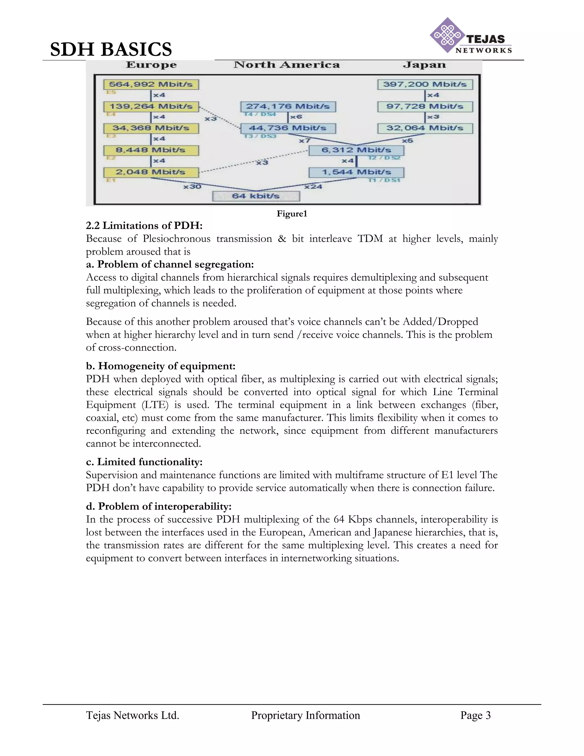
PDH standards are as depicted in Figure1. The European standard named E0, E1, E2 & E4
hierarchy levels and North American standard named DS1, DS2, DS3 & DS4 levels.
E1 Level: Byte interleaved TDM.
32 * 64 KHz = 2.048 Mb/s, Capacity = 30 Base Channels
E2 Level: Bit interleaved TDM
4 * 2.048 +stuffing bits = 8.448 Mbps, Capacity = 120 Base Channels
E3 Level: Bit interleaved TDM
4 * 8.448 + stuffing bits = 34.368 Mbps, Capacity = 480 Base Channels
E4 Level: Bit interleaved TDM
4 * 34.368 +stuffing bits = 139.264 Mbps, Capacity = 1920 Base Channels](https://image.slidesharecdn.com/sdhbasicshandoutsofsdhbasics-210714182232/75/Sdh-basics-hand_outs_of_sdh_basics-2-2048.jpg)
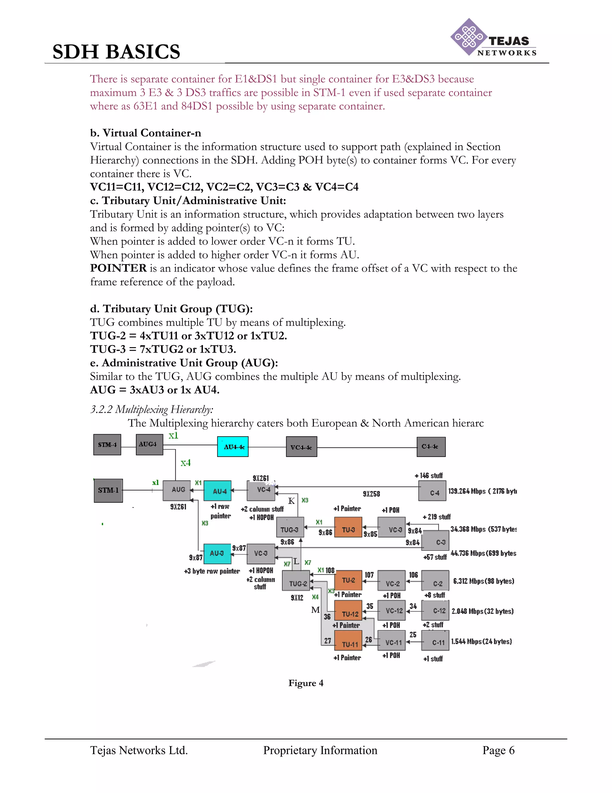
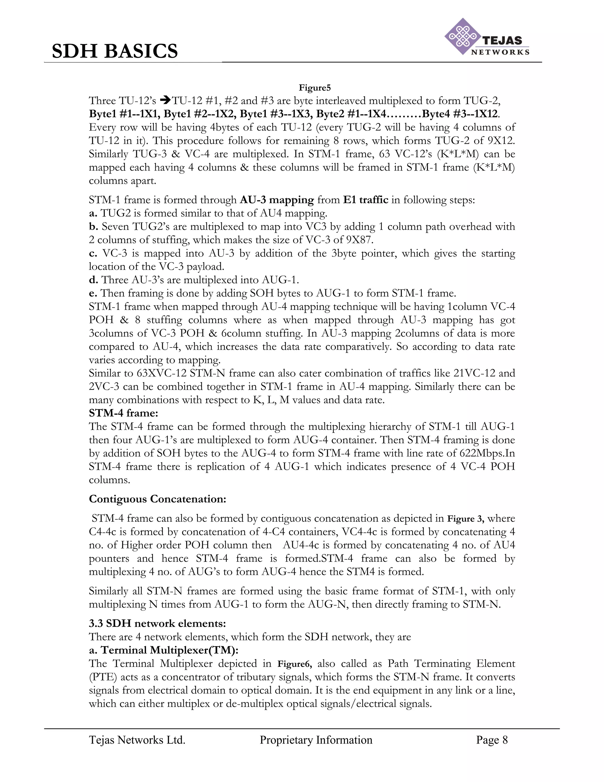
![Tejas Networks Ltd. Proprietary Information Page 4
SDH BASICS
[3] Synchronous Digital Hierarchy (SDH):
Telecommunication Networking formulated by ITU-T (International Telecommunication
Union for Telecommunication standards) and can have capacity upto 40Gbps (not yet
formalized). SDH solved all the problems, which PDH faced by following ways
1. SDH follows the Master-Slave clock technique with PLL (Phase Locked Loop) to
synchronize the nodes.
2. SDH provides mapping, MUXing (byte interleaved TDM) & framing to mainly carry
PDH & Ethernet traffic to form STM frame.
3. Overhead bytes ensure the management of payload & Pointers allow dynamic allocation
of payload in STM frame with which justification can be done under specified limit.
4. Automatic Protection Switching provide protection to traffic against the fiber cut & errors
with the help of overhead bytes in SDH.
5. Performance Monitoring & Alarms strengthens the SDH by giving sufficient indication
using Overheads bytes against errors like equipment, operator & communication.
SDH does not multiplex in predefined steps; one unit is multiplexing all incoming links, adds
overhead information and creates a synchronous transport module (STM).
3.1 STM frame structure:
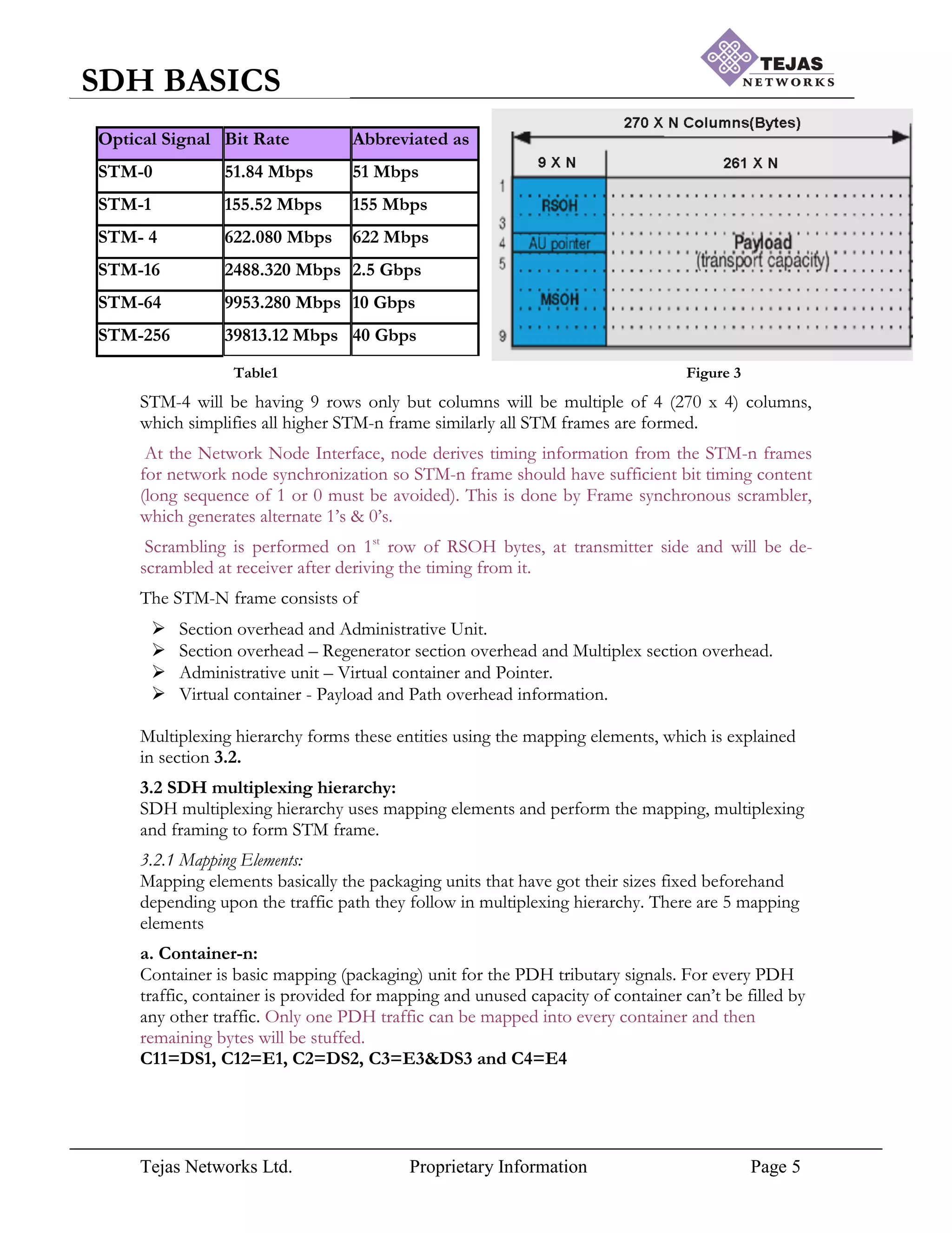
The STM frame standards with line rate are as shown in Table1. The zero level of the
synchronous digital hierarchy shall be 51 Mbps. The first level of the synchronous digital
hierarchy shall be 155Mbps. Higher synchronous digital hierarchy bit rates shall be obtained
as integer multiples of the first level bit rate and shall be denoted by the corresponding
multiplication factor of the first level rate.
The STM-1 frame is the basic transmission format for SDH. The frame lasts for 125µSec as
depicted in Figure2.The STM-n frame is arranged in matrix format and STM-1 frame
structure is having 9 rows X 270 columns and hence has 2430 bytes within 125µSec, which
forms the line rate of 155Mbps(2430X64Kbps). Similarly the STM-N frame is formed, will
be having 9 rows only but columns
Figure2
will be multiplied, which is nothing but column multiplexing and is as depicted in Figure3.
The STM-n frames are transmitted in left-right and top-bottom manner, i.e. 1st
row is
transmitted starting from 1x1 byte and continue upto 1x270 byte, then 2nd
row transmitted in
same manner, 3rd
row,4th
row,…….7th
row.](https://image.slidesharecdn.com/sdhbasicshandoutsofsdhbasics-210714182232/75/Sdh-basics-hand_outs_of_sdh_basics-4-2048.jpg)
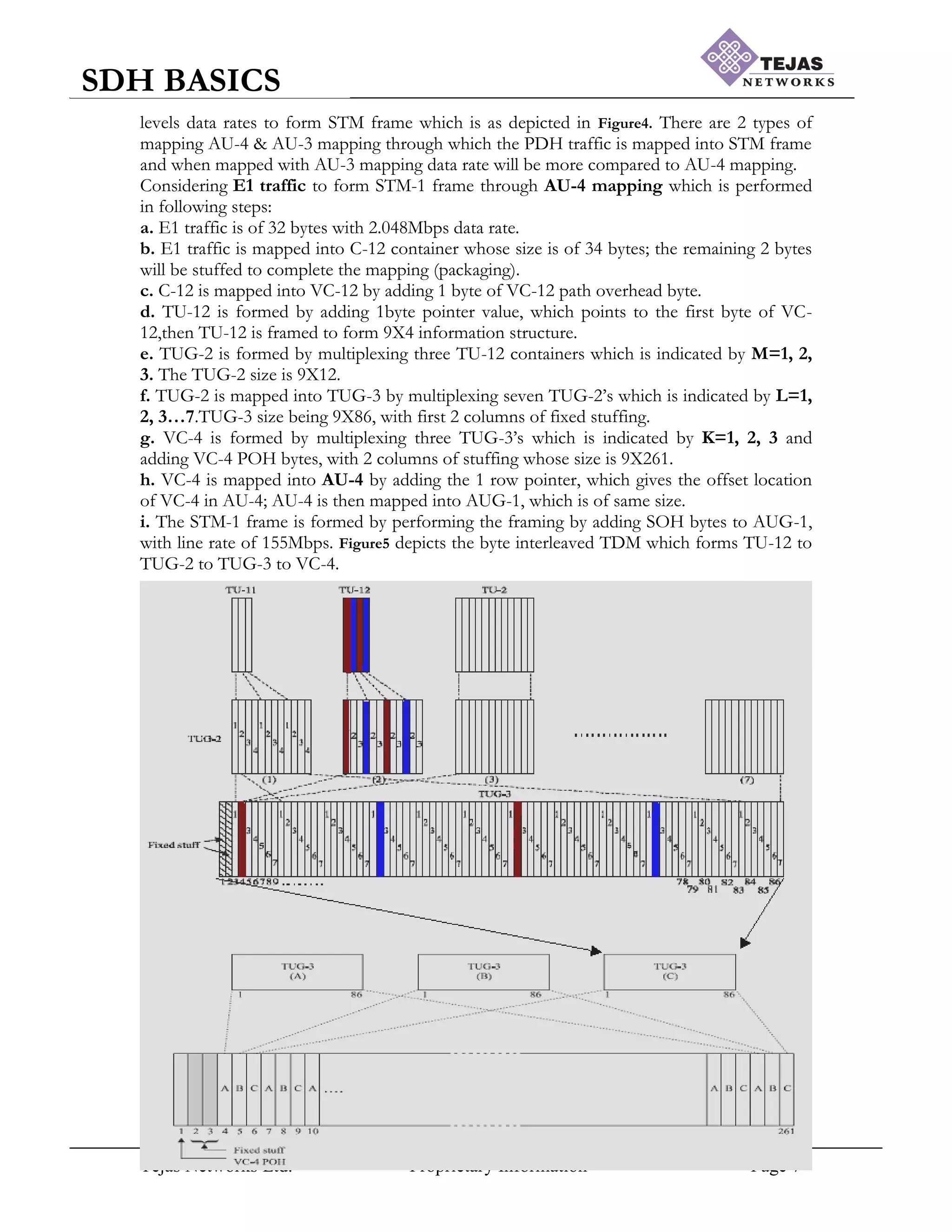
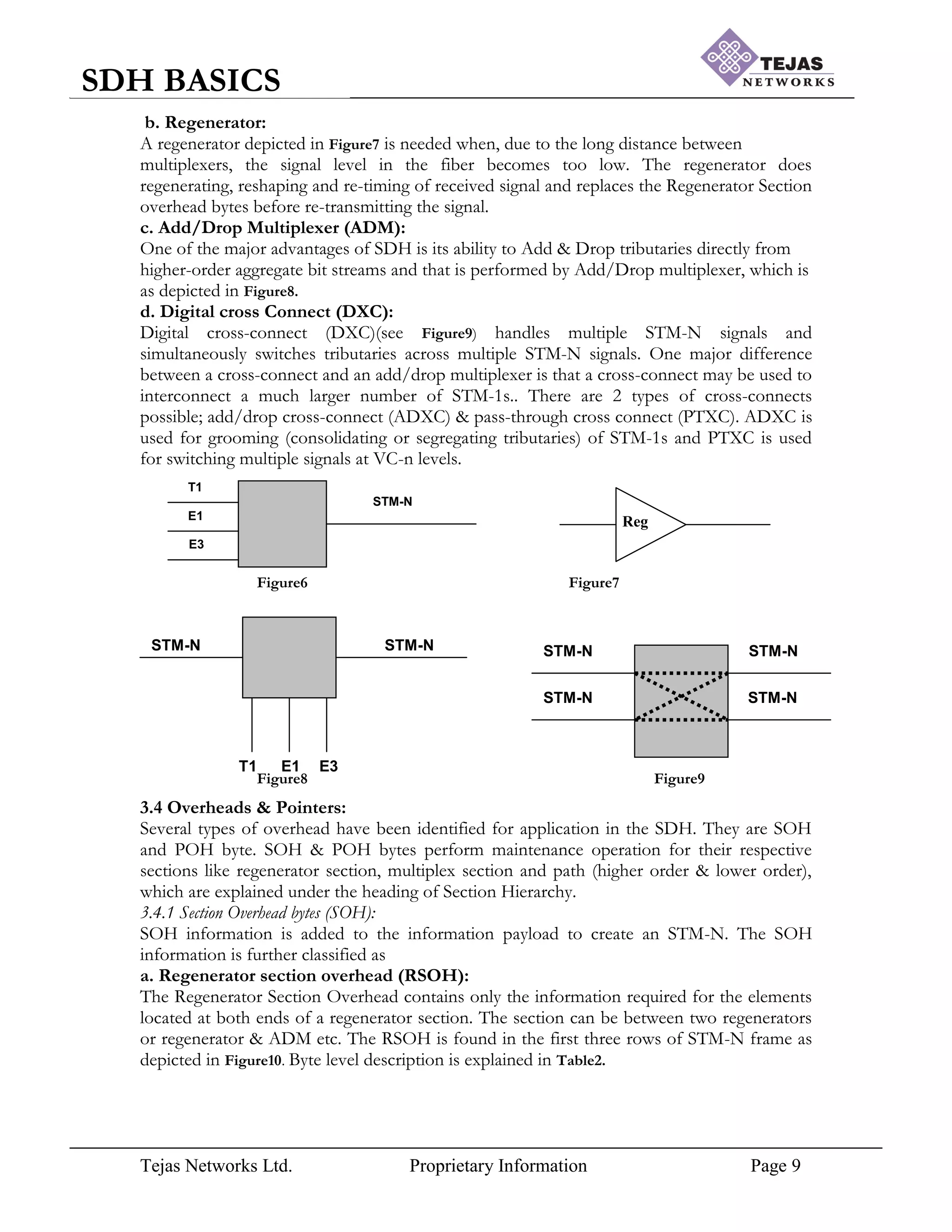
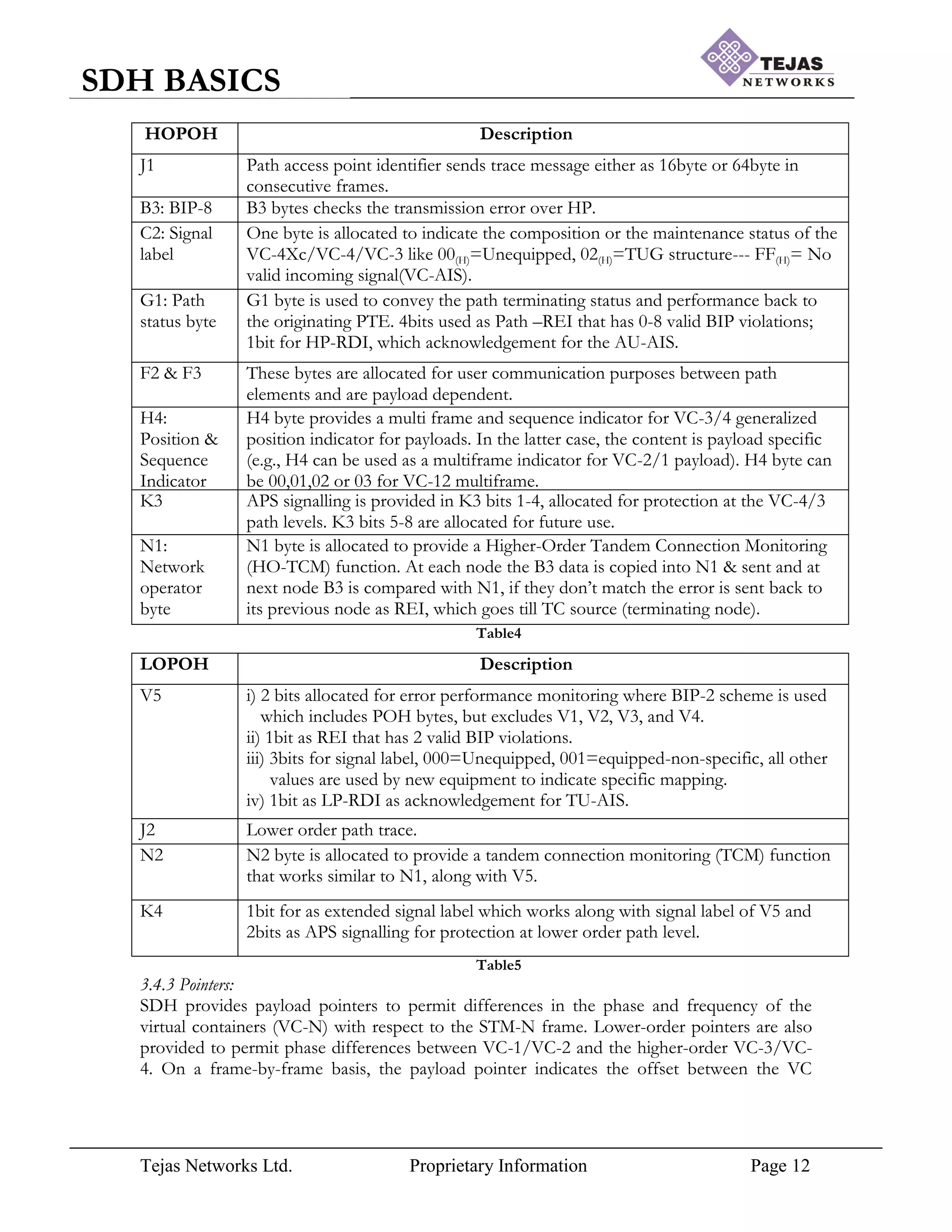
![Tejas Networks Ltd. Proprietary Information Page 14
SDH BASICS
TU-2
TU-12
TU-11
0-427
0-139
0-103
4X107byte(VC-2)=428.
4X35byte(VC-12)=140.
4X26byte(VC-11)=104.
Table6
Figure 12(LO)
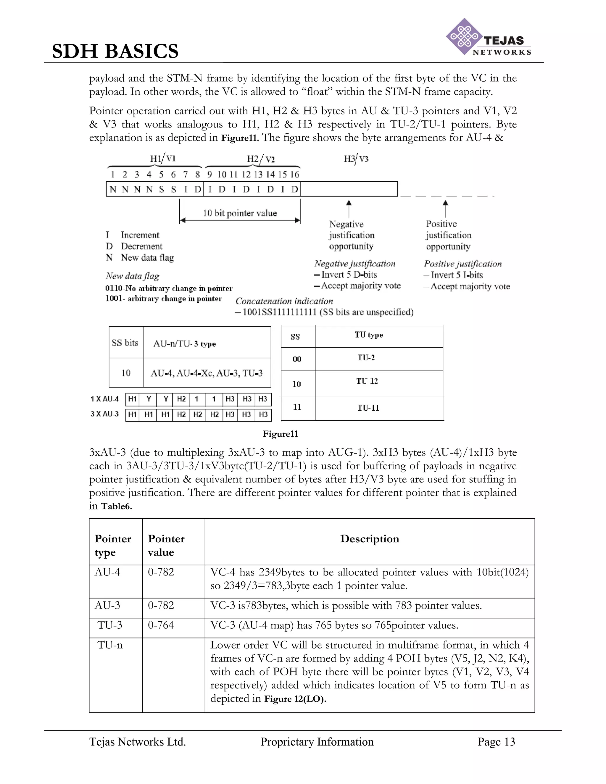
After the pointer value assignment, the hierarchy should be able to process the data even in
case of clock difference between the nodes, which can be because of jitter & wander and in
all cases the hierarchy does the justification. For performing the justification First byte of the
payload should be allocated from 4th
row, immediately after H3 bytes and they can float
anywhere in frame there after. Pointer justification occurs when the sending SDH NE‟s
timing is different than the receiving SDH NE‟s timing. There are 2 types of justification
possible depending upon the clock frequency.
a. Positive Pointer Justification (PPJ):
If the frame rate of the VC-n is too slow with respect to that of the AUG-N, then the
alignment of the VC-n must periodically slip back in time as depicted in Figure12 [a], where
there are 2 nodes (NE1 & NE2) in network, VC-n data rate of NE1 is 782bytes/sec &
AUG-n data rate of NE2 is 783bytes/sec(reference clock recovered) with respective number
of pointers. Because of the difference in clock rate, when NE1 sends only 782bytes, which
will fill the NE2 buffer with leaving 1byte empty (1 pointer no information is present) and
the pointer is pointing to the 1st
position, this is where positive pointer justification is used.
Pointer value is showing the false pointer value where as actual data starts from 2nd
position,
so for that stuffing byte is added at 1st
position (doesn‟t contribute for payload) & pointer
incremented from position 1(dotted arrow) to 2(where actual data starts). This is Positive
Pointer Justification (PPJ). PPJ operation is carried out in 4 consecutive frames as depicted
in Figure12 [b].
Frame-n Start of VC-n, where clock is recovered from incoming bits & set as reference.
Frame (n+1) Pointer initialization, payload slipped back because clock difference.
Frame (n+2) Pointer value I bits inverted to have 5bit majority voting at receiver &
stuffing bytes added after 3H3 bytes.
Frame (n+3) Pointer value incremented by 1.
NE2](https://image.slidesharecdn.com/sdhbasicshandoutsofsdhbasics-210714182232/75/Sdh-basics-hand_outs_of_sdh_basics-14-2048.jpg)
![Tejas Networks Ltd. Proprietary Information Page 15
SDH BASICS
783
NE1
VC-n AUG-n
Figure12 [a]
Figure12 [b]
b. Negative Pointer Justification (NPJ):
If the frame rate of the VC-n is too fast with respect to that of the AUG-N, then the
alignment of the VC-n must periodically be advanced in time as depicted in Figure13 [a],
where VC-n data rate is 784bytes/sec and AUG-n data rate of adjacent node is 783bytes/sec
(reference clock recovered). When NE1 sends the data all 783 positions (50-783 in nth frame
to 49 shown in figure) of NE2 are filled with data sent by NE1, even then 1 byte is
remaining which has to be accommodated in frame of NE2, this is done by vacating the
H3H3H3 bytes, because of which payload is moved in that place and the remaining data is
included within payload by decrementing the pointer from 50 to 49.NPJ operation is carried
out in 4 consecutive frames as depicted in Figure13 [b]. It is similar to PPJ till frame (n+1),
Frame (n+2)Pointer value D bits inverted to have 5bit majority voting at receiver &
Buffering is done in H3 bytes where payload data is loaded (which is extra in VC-n)
Frame (n+3) Pointer value decremented by 1.
VC-n(NE1) AUG-n(NE2)
Figure13 [a]
Figure13 [b]
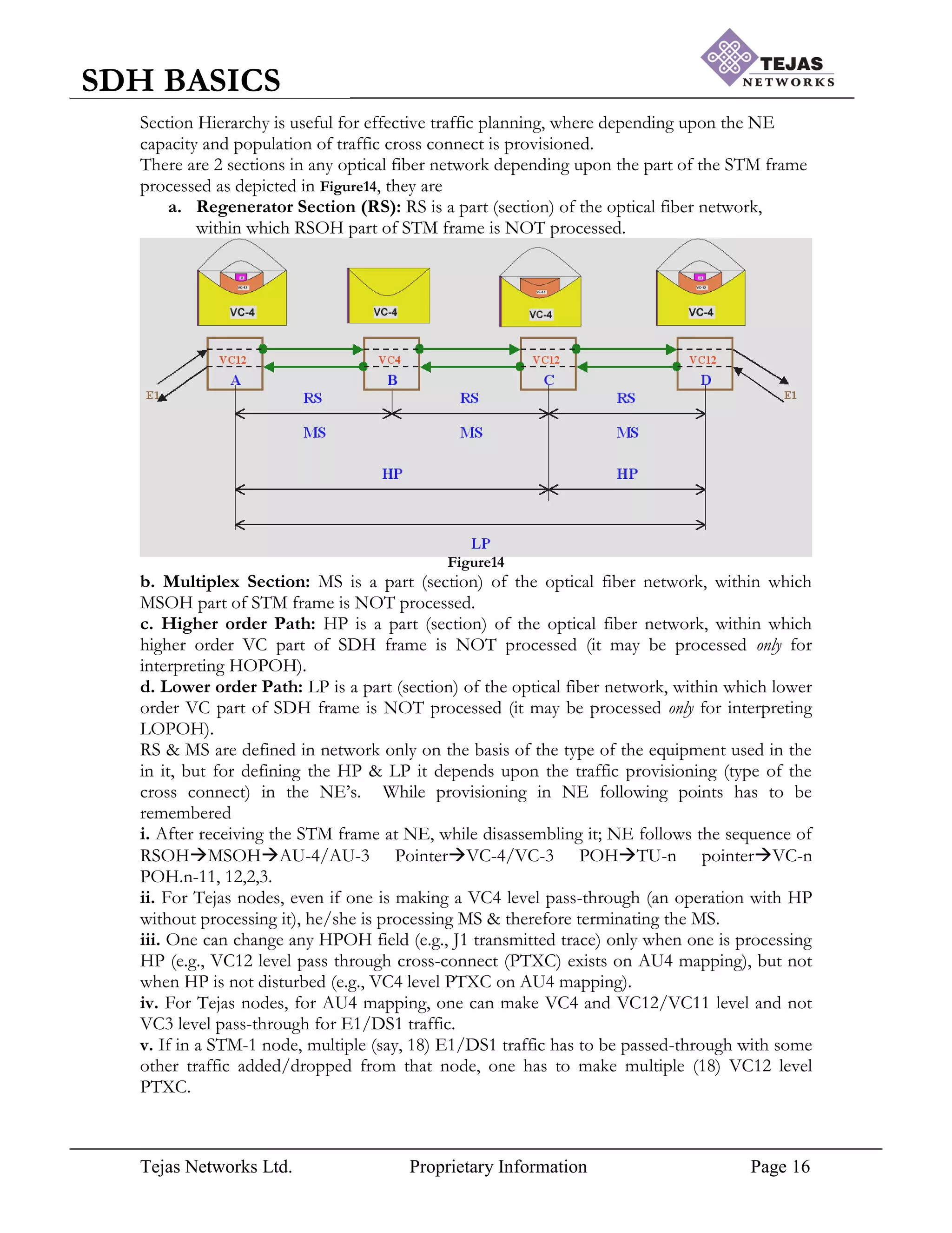
[4] Section Hierarchy:
1
2
3
|
|
|
|
780
781
782
1
1q1
2
3
4
|
|
|
|
781
782
783
1
1q1
2
3
4
|
|
|
|
782
783
784
50
51
52
|
782
783
0
1
|
48
49
49](https://image.slidesharecdn.com/sdhbasicshandoutsofsdhbasics-210714182232/75/Sdh-basics-hand_outs_of_sdh_basics-15-2048.jpg)
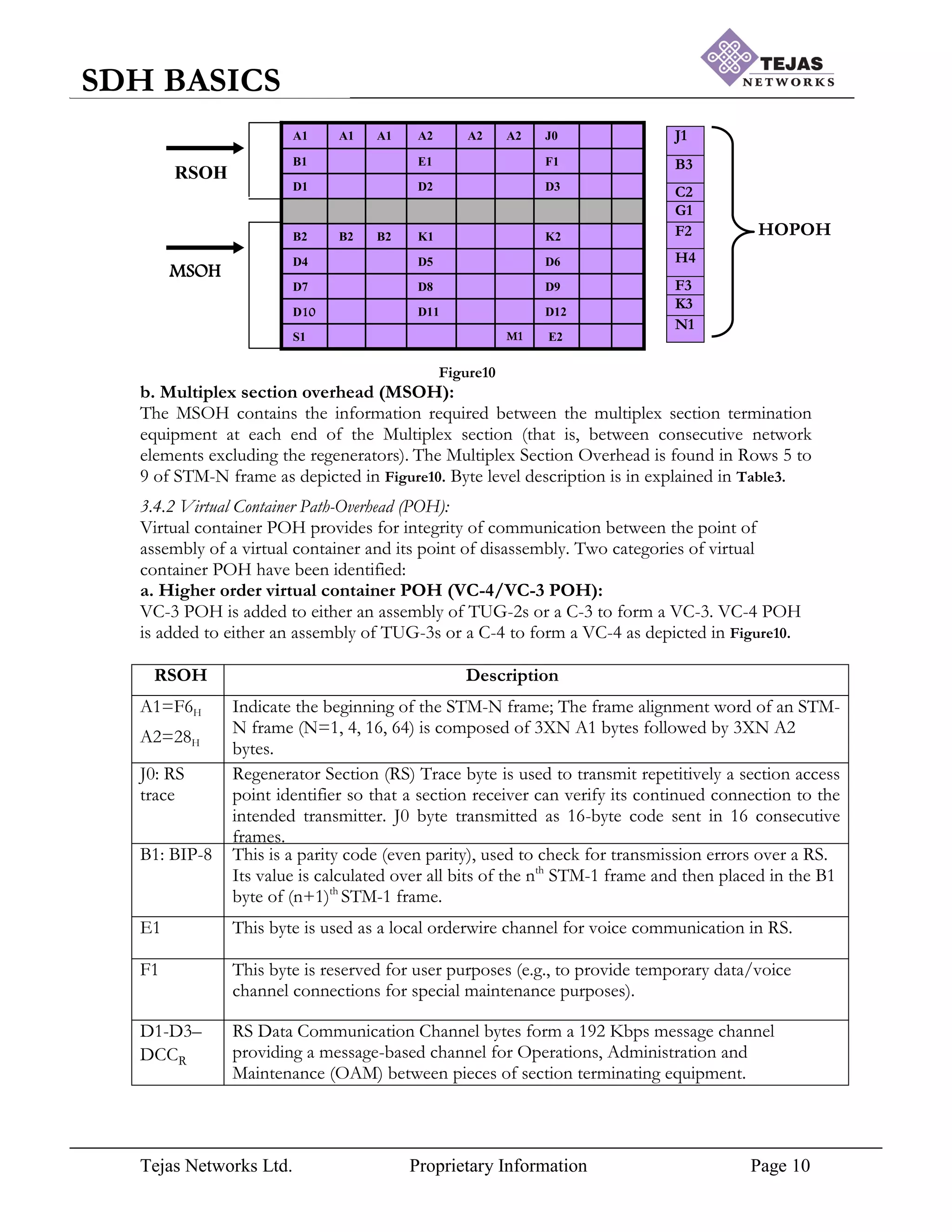
![Tejas Networks Ltd. Proprietary Information Page 18
SDH BASICS
[5] Automatic Protection Switching (APS):
Protection is required for the traffic against 3 conditions Signal Degrade (SD), Signal Failure
(SF) and fiber cut. When first 2 conditions occur the traffic quality will be lost and in the
later case traffic itself will be lost. So there was service level agreement done between service
provider & customer, according to which 99.999% of the time connection should be
available and this is possible only by Automatic Protection Switching. APS can be classified
in general as
i. 1+1 protection scheme/Dedicated protection scheme
The simplest of all the forms is the 1+1 type of protection. Each working line (port or path)
is protected by one dedicated protection line (port or path). Protection line is redundant line
dedicated for the working line. Traffic is taken through both working line & protection line
simultaneously and at the far end traffic will be selected by switch depending upon the
healthiness of the traffic. The switch over is triggered by a defect such as fiber cut, SF or SD.
When working line is on the toss, traffic will be selected from the protection line. The main
disadvantage of the 1+1 is high bandwidth redundancy but 1+1 is faster than any of the
protection-switching scheme.
ii. 1:1 protection scheme/Shared protection scheme
1:1 in general can be called as 1:N; in 1:1 protection for each of the working line (which can
be either port or path) there will be a corresponding protection line. There will be 2 types of
traffics identified for catering it, high priority traffic & low priority traffic (Not supported in
Tejas products). High priority traffic will be catered in the working line and low priority
traffic will be taken through protection line. When the working line goes on the toss, traffic
has to be catered through protection line where low priority traffic is present, which will be
pre-empted from protection line for serving the high priority traffic.
In 1:N there will be N working line, which are getting protected by 1 protection line through
which low priority traffic is catered and the switching occurs depending upon the priority
given to the working line and low priority traffic will be given least priority.
Above said 2 protection schemes can be discussed in detail based on network topology,
which are
5.1. Linear protection scheme:
1+1 & 1:N protection switching scheme when deployed in linear network will be termed as
linear protection switching scheme.
a.1+1 MSP:
1+1 protection scheme in linear network are termed as 1+1 MSP as each section in our
Tejas optical network is MS. Figure16 depicts the normal operation of the 1+1 MSP, where
communication needs to establish between 2 NE‟s A & B.
Figure16
1+1 MSP is port level protection scheme where traffic catered in one port called as Working
port (3-1 or 4-1) as depicted will be protected by Protecting port (3-2 or 4-2). Each port will
be having Tx. & Rx fiber which will be connected to its adjacent port to Rx. & Tx.
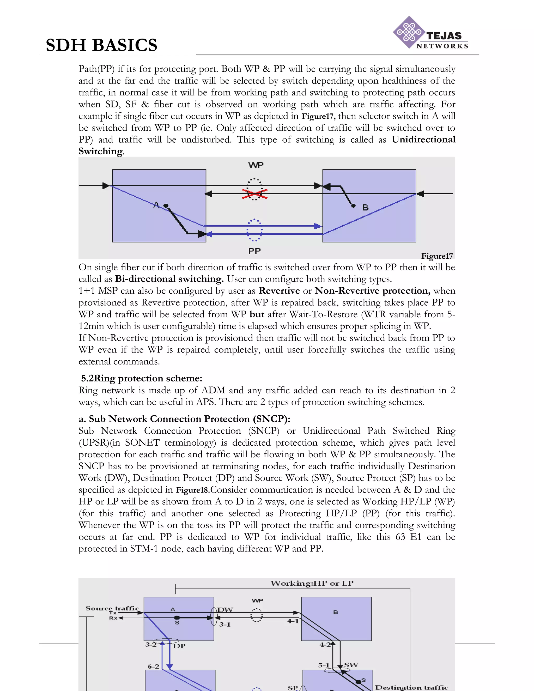
respectively, which will be either Working Path (WP) if its for working port & Protecting](https://image.slidesharecdn.com/sdhbasicshandoutsofsdhbasics-210714182232/75/Sdh-basics-hand_outs_of_sdh_basics-18-2048.jpg)
![Tejas Networks Ltd. Proprietary Information Page 22
SDH BASICS
External commands enable the user to have control over routing of the traffic whenever
application arises. There are 4 external commands whose priority is given by 4bits of K1
byte.
a. Clear/Release
This external command clears all external commands applied on any port, which is having
the highest priority.
b. Lock Out of Protection (LOP):
Lock out of protection is external command given by user, when maintenance operation has
to be carried on the PP, in which case if WP goes on the toss traffic continuously tries to
acquire the PP and selector switch keeps on switching between WP & PP. To avoid this
loop LOP is given so that PP is locked & no traffic will be allowed to go through PP.
c. Forced Switch: Work or Protect
Forced Switch is the explicit command, which forcefully switches traffic to intended path; it
can be Forced Switch to Work or Forced Switch to Protect. The switching takes place
regardless of condition of the path to which it is switching to because SF/SD are of lower
priority compared to this command.
d. Manual Switch: work or Protect
Manual switch is similar to the Forced switch but main difference is while switching the
traffic, condition of the path is checked as SF/SD are of higher priority. Hence whenever
Manual switch to work is given and WP is having SF/SD then switching doesn‟t take place.
Following table illustrates the different types of protection switching schemes.
Protection
Schemes
Topology
Uni-Directional
/ Bi-Directional
Revertive /
Non-Revertive
Shared /
Dedicated
Switching
Time
1+1 MSP
(Port protection)
Linear Uni / Bi-
Directional
Revertive /
Non-Revertive
Dedicated Low
1+1 SNCP
(Path protection)
Ring Uni-Directional
(UPSR)
Revertive /
Non-Revertive
Dedicated Low
MSSP2F
(Line protection)
Ring Bi-Directional
(BLSR)
Revertive Shared Switching
time is more
MSSP4F
(Line protection)
Ring Bi-Directional
(BLSR)
Revertive /
Non-Revertive
Shared Switching
time is more
1:N
(Card
protection)
Linear NA Revertive/Non
Revertive
Shared Switching
time is more
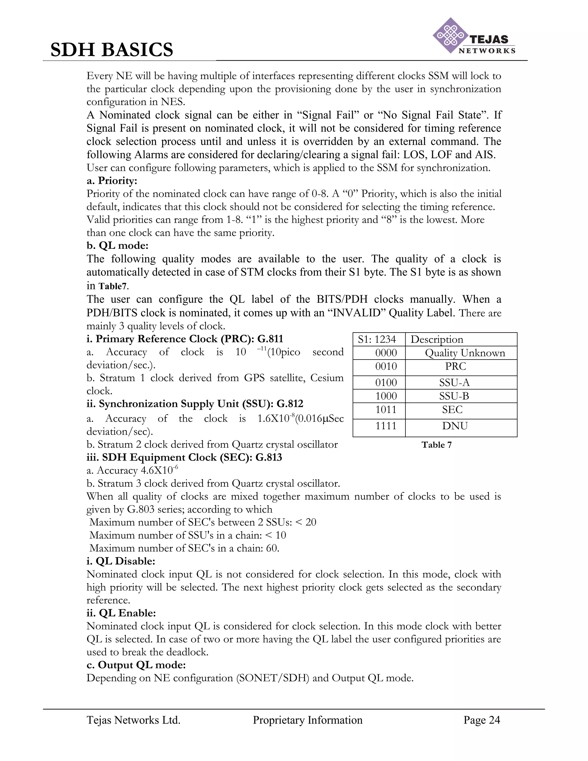
[6] Synchronization:
Synchronization is required to enable service providers to transport bits of information
within and across network without losing any bits, which can be due to mis-timing (phase](https://image.slidesharecdn.com/sdhbasicshandoutsofsdhbasics-210714182232/75/Sdh-basics-hand_outs_of_sdh_basics-22-2048.jpg)
![Tejas Networks Ltd. Proprietary Information Page 26
SDH BASICS
VCO
Offset
Regist
er
Output
frequency (f0)
Nominated clock (fR)
Controlled Oscillator (VCO) Output Frequency will be synthesized. SSM will keep on
surveying clock & will be indicating to user with the help of SETG status and resulting
alarms.
Figure 24
a. SETG (Synchronous Equipment Timing Generation) status:
The SETG status is the indicator of what state the SSM module is in. It has the following
states:
i. Free Running: When the offset register value is completely ignored, PLL becomes an
open loop system. The output frequency cannot be tracked to the nominated clock or no
external clock is nominated or in holdover mode for more than 24 hours.
ii. Holdover: The offset register value is fixed to the last value when both inputs were
available or the Timing reference on all nominated clocks failed or PPM offset on
selected clock is high (> +/- 17 PPM).
iii. Lock: The offset register value in PLL changes dynamically to track the output
frequency to the input frequency and thus, derives timing from the nominated clock
source. The node also shows which timing source it is deriving its reference from by
indicating a “*” against the Timing reference which is current reference clock.
b. Alarms:
SM provides following Alarms to indicates the current status of SSM
i. Timing reference failed:
This alarm is raised whenever nominated clock source has LOS, LOF or AIS or if the
Primary or the Secondary clock PPM offset is higher than +/- 17 PPM.
ii. System clock in holdover mode:
This alarm is raised in the following scenarios.
a. Current selected clock received signal fail and no other nominated clock is available for
timing reference.
b. Current selected clock PPM offset crosses +/-17PPM
iii. Timing generation entry free run:
This alarm will be generated when
a. No clock is nominated for timing reference.
b. Internal clock is selected as reference clock.
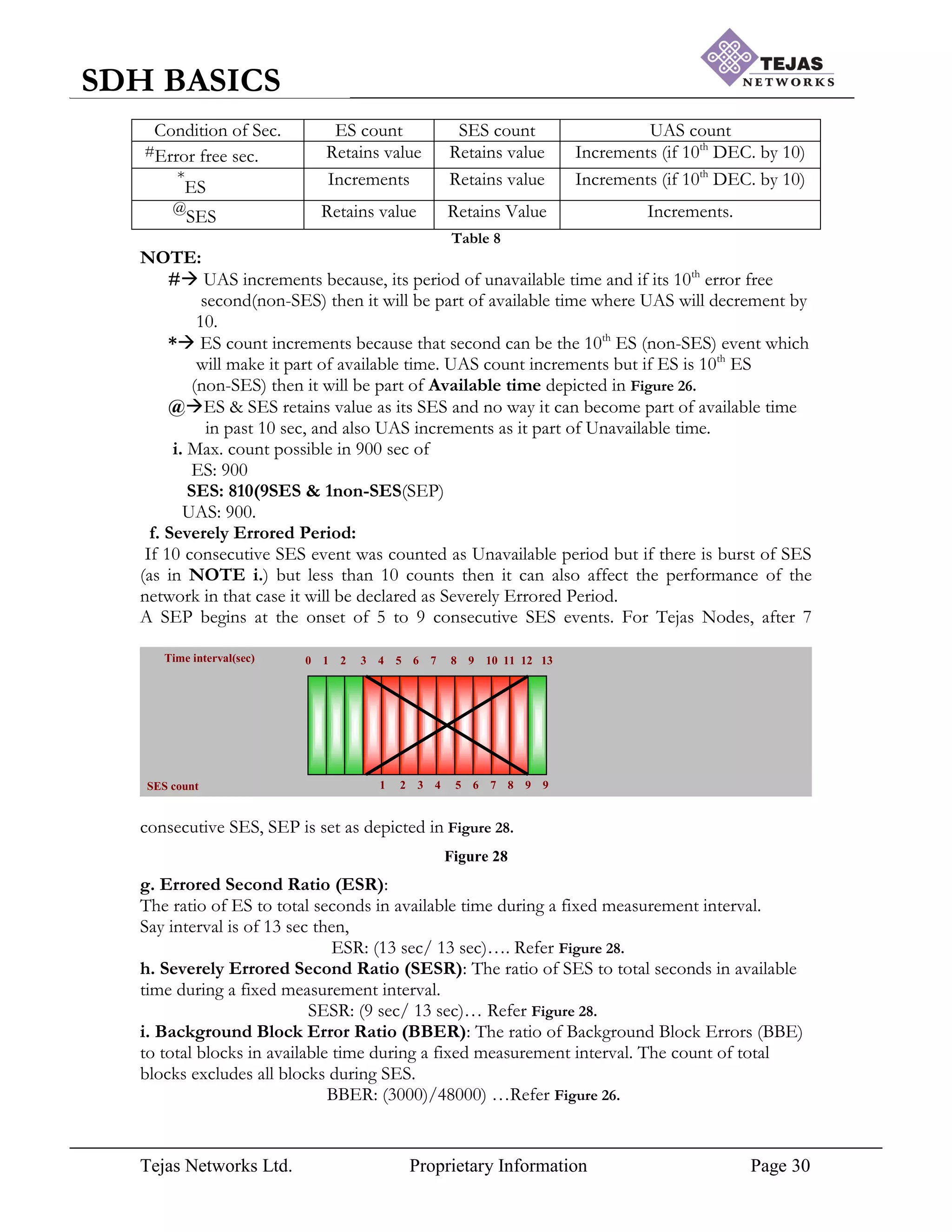
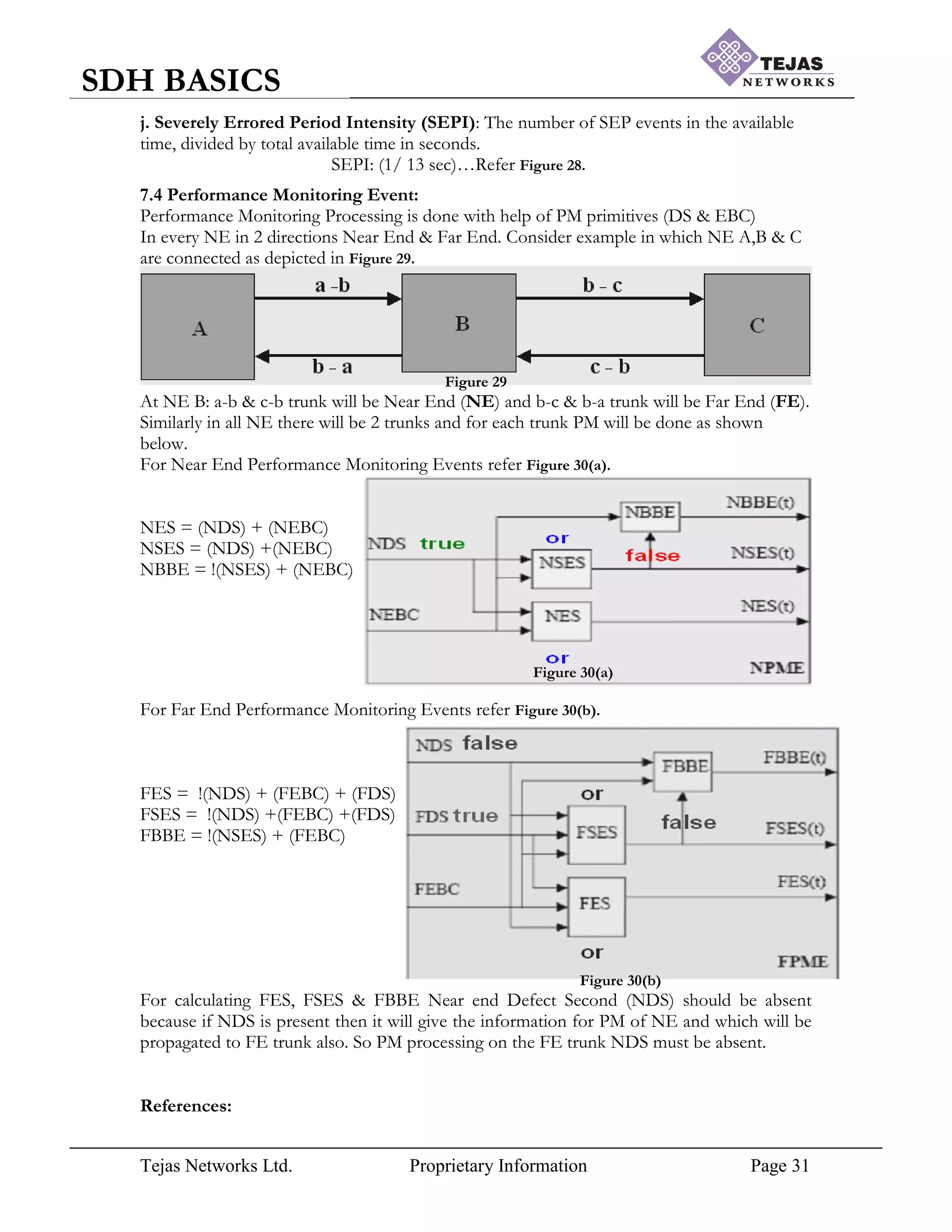
[7] Performance Monitoring (PM) Parameters:
Even though Digital Communication is immune to noise addition, noise set to occur in
transmission and performance is inversely proportional to the noise, hence performance of
the hierarchy is going to change accordingly. In STM frame while carrying the voice “data” is](https://image.slidesharecdn.com/sdhbasicshandoutsofsdhbasics-210714182232/75/Sdh-basics-hand_outs_of_sdh_basics-26-2048.jpg)
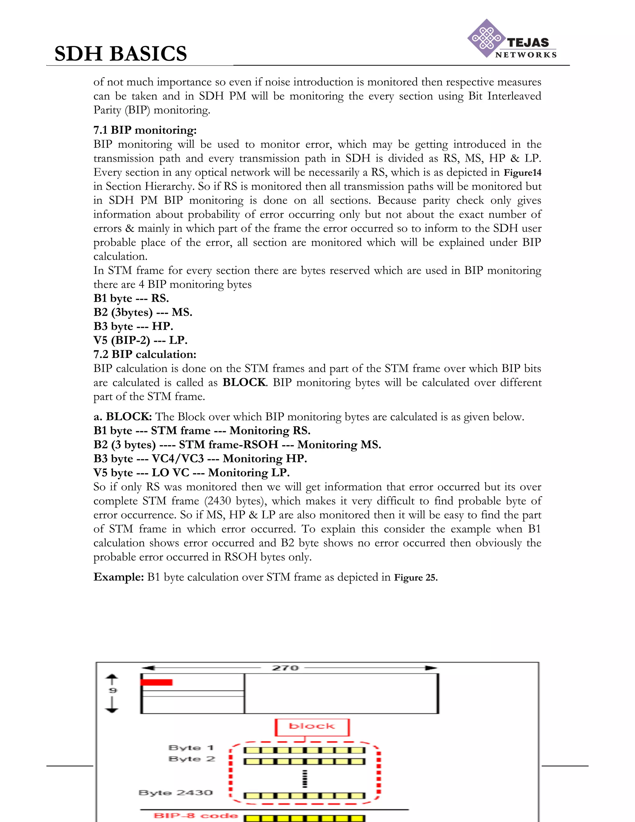


Digital communication uses digital signals that have discrete states (on/off) instead of continuous amplitudes like analog signals. This allows for higher quality transmission with less noise and distortion. SDH (Synchronous Digital Hierarchy) was developed to address limitations of earlier PDH (Plesiochronous Digital Hierarchy) transmission, which used almost synchronous clocks. SDH uses a master-slave clock technique and overhead bytes to provide synchronization across nodes, manage payloads, and enable features like automatic protection switching and performance monitoring. The basic SDH frame is STM-1, which has 9 rows and 270 columns for a total of 2430 bytes transmitted every 125 microseconds at 155 Mbps. Higher STM frames are formed by multiplying the


![Number_Guessing_Game_Dsbsbssbzboc[1].pptx](https://cdn.slidesharecdn.com/ss_thumbnails/numberguessinggamedoc1-251206215042-a076fc05-thumbnail.jpg?width=640&height=640&fit=bounds)