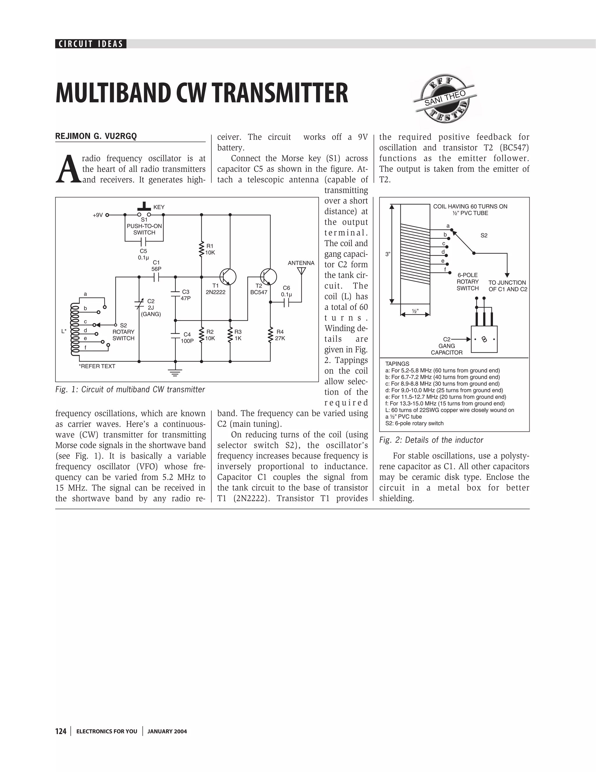
SlideShare a Scribd company logo
1 of 1
Download to read offline
CIRCUIT IDEAS


MULTIBAND CW TRANSMITTER                                                                                SAN
                                                                                                              I THE
                                                                                                                      O


REJIMON G. VU2RGQ                             ceiver. The circuit works off a 9V           the required positive feedback for
                                              battery.                                     oscillation and transistor T2 (BC547)


A
       radio frequency oscillator is at           Connect the Morse key (S1) across        functions as the emitter follower.
       the heart of all radio transmitters    capacitor C5 as shown in the figure. At-     The output is taken from the emitter of
       and receivers. It generates high-      tach a telescopic antenna (capable of        T2.
                                                                           transmitting
                                                                           over a short
                                                                           distance) at
                                                                           the output
                                                                           terminal.
                                                                           The coil and
                                                                           gang capaci-
                                                                           tor C2 form
                                                                           the tank cir-
                                                                           cuit. The
                                                                           coil (L) has
                                                                           a total of 60
                                                                           t u r n s .
                                                                           Winding de-
                                                                           tails     are
                                                                           given in Fig.
                                                                           2. Tappings
                                                                           on the coil
                                                                           allow selec-
Fig. 1: Circuit of multiband CW transmitter                                tion of the
                                                                           required
frequency oscillations, which are known       band. The frequency can be varied using
as carrier waves. Here’s a continuous-        C2 (main tuning).
wave (CW) transmitter for transmitting            On reducing turns of the coil (using
                                                                                           Fig. 2: Details of the inductor
Morse code signals in the shortwave band      selector switch S2), the oscillator’s
(see Fig. 1). It is basically a variable      frequency increases because frequency is         For stable oscillations, use a polysty-
frequency oscillator (VFO) whose fre-         inversely proportional to inductance.        rene capacitor as C1. All other capacitors
quency can be varied from 5.2 MHz to          Capacitor C1 couples the signal from         may be ceramic disk type. Enclose the
15 MHz. The signal can be received in         the tank circuit to the base of transistor   circuit in a metal box for better
the shortwave band by any radio re-           T1 (2N2222). Transistor T1 provides          shielding.


124   ELECTRONICS FOR YOU   JANUARY 2004

More Related Content

What's hot

Interconnect timing model
Interconnect  timing modelInterconnect  timing model
Interconnect timing modelPrachi Pandey
 
Pump control with flow line pressure monitoring
Pump control with flow line pressure monitoringPump control with flow line pressure monitoring
Pump control with flow line pressure monitoringAsif Sheriff
 
Electric window fence charger
Electric window fence chargerElectric window fence charger
Electric window fence chargerviv3ksharma
 
The wire
The wireThe wire
The wiresdpable
 
Dee 6113 CMOS IC DESIGN (Chapter 3 ~ CMOS inverter)
Dee 6113 CMOS IC DESIGN (Chapter 3 ~ CMOS inverter)Dee 6113 CMOS IC DESIGN (Chapter 3 ~ CMOS inverter)
Dee 6113 CMOS IC DESIGN (Chapter 3 ~ CMOS inverter)MielWitwicky
 
Nptel cad2-06 capcitances
Nptel cad2-06 capcitancesNptel cad2-06 capcitances
Nptel cad2-06 capcitanceschenna_kesava
 
B )mos transistor fabrication problem
B )mos transistor fabrication problemB )mos transistor fabrication problem
B )mos transistor fabrication problemViruss Alona
 
Double Side Band – Suppressed Carrier (DSB-SC) Modulation Demodulation using ...
Double Side Band – Suppressed Carrier (DSB-SC) Modulation Demodulation using ...Double Side Band – Suppressed Carrier (DSB-SC) Modulation Demodulation using ...
Double Side Band – Suppressed Carrier (DSB-SC) Modulation Demodulation using ...Akshay Sharma
 
CMOS Topic 5 -_cmos_inverter
CMOS Topic 5 -_cmos_inverterCMOS Topic 5 -_cmos_inverter
CMOS Topic 5 -_cmos_inverterIkhwan_Fakrudin
 
4666 4670.output
4666 4670.output4666 4670.output
4666 4670.outputj1075017
 

What's hot (17)

Interconnect timing model
Interconnect  timing modelInterconnect  timing model
Interconnect timing model
 
Microwave
MicrowaveMicrowave
Microwave
 
Lecture18
Lecture18Lecture18
Lecture18
 
Pump control with flow line pressure monitoring
Pump control with flow line pressure monitoringPump control with flow line pressure monitoring
Pump control with flow line pressure monitoring
 
Electric window fence charger
Electric window fence chargerElectric window fence charger
Electric window fence charger
 
The wire
The wireThe wire
The wire
 
Am9
Am9Am9
Am9
 
CMOS Topic 4 -_the_wire
CMOS Topic 4 -_the_wireCMOS Topic 4 -_the_wire
CMOS Topic 4 -_the_wire
 
Matching techniques
Matching techniquesMatching techniques
Matching techniques
 
15
1515
15
 
Dee 6113 CMOS IC DESIGN (Chapter 3 ~ CMOS inverter)
Dee 6113 CMOS IC DESIGN (Chapter 3 ~ CMOS inverter)Dee 6113 CMOS IC DESIGN (Chapter 3 ~ CMOS inverter)
Dee 6113 CMOS IC DESIGN (Chapter 3 ~ CMOS inverter)
 
Nptel cad2-06 capcitances
Nptel cad2-06 capcitancesNptel cad2-06 capcitances
Nptel cad2-06 capcitances
 
B )mos transistor fabrication problem
B )mos transistor fabrication problemB )mos transistor fabrication problem
B )mos transistor fabrication problem
 
Double Side Band – Suppressed Carrier (DSB-SC) Modulation Demodulation using ...
Double Side Band – Suppressed Carrier (DSB-SC) Modulation Demodulation using ...Double Side Band – Suppressed Carrier (DSB-SC) Modulation Demodulation using ...
Double Side Band – Suppressed Carrier (DSB-SC) Modulation Demodulation using ...
 
CMOS Topic 5 -_cmos_inverter
CMOS Topic 5 -_cmos_inverterCMOS Topic 5 -_cmos_inverter
CMOS Topic 5 -_cmos_inverter
 
4666 4670.output
4666 4670.output4666 4670.output
4666 4670.output
 
Lecture08
Lecture08Lecture08
Lecture08
 

Similar to Multiband cw transmitter

Traffic controller
Traffic controllerTraffic controller
Traffic controllerviv3ksharma
 
Active inductor design new
Active inductor design newActive inductor design new
Active inductor design newDEVITH T
 
3. the-wireless-channel-2
3. the-wireless-channel-23. the-wireless-channel-2
3. the-wireless-channel-2Naga Sirisha
 
Phase Shift, Collpitt's and Crystal oscillators.pptx
Phase Shift, Collpitt's and Crystal oscillators.pptxPhase Shift, Collpitt's and Crystal oscillators.pptx
Phase Shift, Collpitt's and Crystal oscillators.pptxProfVilasShamraoPati
 
Phase Shift, Collpitt's and Crystal oscillators.pptx
Phase Shift, Collpitt's and Crystal oscillators.pptxPhase Shift, Collpitt's and Crystal oscillators.pptx
Phase Shift, Collpitt's and Crystal oscillators.pptxProfVilasShamraoPati
 
balanced modulator.pptx breif introduction
balanced modulator.pptx breif introductionbalanced modulator.pptx breif introduction
balanced modulator.pptx breif introductionLingampalliAbhijith
 
Automated alarm circuits
Automated alarm circuitsAutomated alarm circuits
Automated alarm circuitsviv3ksharma
 
EC8651 Transmissions lines and RF systems-two marks
EC8651  Transmissions lines and RF systems-two marksEC8651  Transmissions lines and RF systems-two marks
EC8651 Transmissions lines and RF systems-two marksDr.SHANTHI K.G
 
Chapter 20
Chapter 20Chapter 20
Chapter 20Tha Mike
 
Electronic watchdog
Electronic watchdogElectronic watchdog
Electronic watchdogviv3ksharma
 

Similar to Multiband cw transmitter (20)

Traffic controller
Traffic controllerTraffic controller
Traffic controller
 
Demodulation
DemodulationDemodulation
Demodulation
 
Current sensor
Current sensorCurrent sensor
Current sensor
 
20-Radiophone-Diagrams.pdf
20-Radiophone-Diagrams.pdf20-Radiophone-Diagrams.pdf
20-Radiophone-Diagrams.pdf
 
Active inductor design new
Active inductor design newActive inductor design new
Active inductor design new
 
3. the-wireless-channel-2
3. the-wireless-channel-23. the-wireless-channel-2
3. the-wireless-channel-2
 
Phase Shift, Collpitt's and Crystal oscillators.pptx
Phase Shift, Collpitt's and Crystal oscillators.pptxPhase Shift, Collpitt's and Crystal oscillators.pptx
Phase Shift, Collpitt's and Crystal oscillators.pptx
 
Phase Shift, Collpitt's and Crystal oscillators.pptx
Phase Shift, Collpitt's and Crystal oscillators.pptxPhase Shift, Collpitt's and Crystal oscillators.pptx
Phase Shift, Collpitt's and Crystal oscillators.pptx
 
Oscillator
OscillatorOscillator
Oscillator
 
Clap switch
Clap switchClap switch
Clap switch
 
balanced modulator.pptx breif introduction
balanced modulator.pptx breif introductionbalanced modulator.pptx breif introduction
balanced modulator.pptx breif introduction
 
Project
ProjectProject
Project
 
Acmanual ww8
Acmanual ww8Acmanual ww8
Acmanual ww8
 
Amplitude modulation
Amplitude modulationAmplitude modulation
Amplitude modulation
 
Automated alarm circuits
Automated alarm circuitsAutomated alarm circuits
Automated alarm circuits
 
Lesson2
Lesson2Lesson2
Lesson2
 
EC8651 Transmissions lines and RF systems-two marks
EC8651  Transmissions lines and RF systems-two marksEC8651  Transmissions lines and RF systems-two marks
EC8651 Transmissions lines and RF systems-two marks
 
Chapter 20
Chapter 20Chapter 20
Chapter 20
 
Electronic watchdog
Electronic watchdogElectronic watchdog
Electronic watchdog
 
Ep24889895
Ep24889895Ep24889895
Ep24889895
 

More from viv3ksharma

Friendly charger for mobile phones
Friendly charger for mobile phonesFriendly charger for mobile phones
Friendly charger for mobile phonesviv3ksharma
 
Flashing cum running light
Flashing cum running lightFlashing cum running light
Flashing cum running lightviv3ksharma
 
Fire alarm using thermistor
Fire alarm using thermistorFire alarm using thermistor
Fire alarm using thermistorviv3ksharma
 
Electronic security system
Electronic security systemElectronic security system
Electronic security systemviv3ksharma
 
Electronic bicycle lock
Electronic bicycle lockElectronic bicycle lock
Electronic bicycle lockviv3ksharma
 
Dtmf reciever ic mt 8870 tester
Dtmf reciever ic mt 8870 testerDtmf reciever ic mt 8870 tester
Dtmf reciever ic mt 8870 testerviv3ksharma
 
Drinking water alarm
Drinking water alarmDrinking water alarm
Drinking water alarmviv3ksharma
 
Digital stop watch
Digital stop watchDigital stop watch
Digital stop watchviv3ksharma
 
Dice with 7 segment display
Dice with 7 segment displayDice with 7 segment display
Dice with 7 segment displayviv3ksharma
 
Desktop power supply
Desktop power supplyDesktop power supply
Desktop power supplyviv3ksharma
 
Computerised universal timer
Computerised universal timerComputerised universal timer
Computerised universal timerviv3ksharma
 
College quiz buzzer
College quiz buzzerCollege quiz buzzer
College quiz buzzerviv3ksharma
 
Car anti theft guard
Car anti theft guardCar anti theft guard
Car anti theft guardviv3ksharma
 
Brake failure indicator
Brake failure indicatorBrake failure indicator
Brake failure indicatorviv3ksharma
 

More from viv3ksharma (20)

Friendly charger for mobile phones
Friendly charger for mobile phonesFriendly charger for mobile phones
Friendly charger for mobile phones
 
Flying saucer
Flying saucerFlying saucer
Flying saucer
 
Flashing cum running light
Flashing cum running lightFlashing cum running light
Flashing cum running light
 
Flashing beacon
Flashing beaconFlashing beacon
Flashing beacon
 
Fire alarm using thermistor
Fire alarm using thermistorFire alarm using thermistor
Fire alarm using thermistor
 
Electronic security system
Electronic security systemElectronic security system
Electronic security system
 
Electronic horn
Electronic hornElectronic horn
Electronic horn
 
Electronic bicycle lock
Electronic bicycle lockElectronic bicycle lock
Electronic bicycle lock
 
Dtmf reciever ic mt 8870 tester
Dtmf reciever ic mt 8870 testerDtmf reciever ic mt 8870 tester
Dtmf reciever ic mt 8870 tester
 
Drinking water alarm
Drinking water alarmDrinking water alarm
Drinking water alarm
 
Digital stop watch
Digital stop watchDigital stop watch
Digital stop watch
 
Digital dice
Digital diceDigital dice
Digital dice
 
Dice with 7 segment display
Dice with 7 segment displayDice with 7 segment display
Dice with 7 segment display
 
Desktop power supply
Desktop power supplyDesktop power supply
Desktop power supply
 
Computerised universal timer
Computerised universal timerComputerised universal timer
Computerised universal timer
 
College quiz buzzer
College quiz buzzerCollege quiz buzzer
College quiz buzzer
 
Clock timer
Clock timerClock timer
Clock timer
 
Child's lamp
Child's lampChild's lamp
Child's lamp
 
Car anti theft guard
Car anti theft guardCar anti theft guard
Car anti theft guard
 
Brake failure indicator
Brake failure indicatorBrake failure indicator
Brake failure indicator
 

Multiband cw transmitter

  • 1. CIRCUIT IDEAS MULTIBAND CW TRANSMITTER SAN I THE O REJIMON G. VU2RGQ ceiver. The circuit works off a 9V the required positive feedback for battery. oscillation and transistor T2 (BC547) A radio frequency oscillator is at Connect the Morse key (S1) across functions as the emitter follower. the heart of all radio transmitters capacitor C5 as shown in the figure. At- The output is taken from the emitter of and receivers. It generates high- tach a telescopic antenna (capable of T2. transmitting over a short distance) at the output terminal. The coil and gang capaci- tor C2 form the tank cir- cuit. The coil (L) has a total of 60 t u r n s . Winding de- tails are given in Fig. 2. Tappings on the coil allow selec- Fig. 1: Circuit of multiband CW transmitter tion of the required frequency oscillations, which are known band. The frequency can be varied using as carrier waves. Here’s a continuous- C2 (main tuning). wave (CW) transmitter for transmitting On reducing turns of the coil (using Fig. 2: Details of the inductor Morse code signals in the shortwave band selector switch S2), the oscillator’s (see Fig. 1). It is basically a variable frequency increases because frequency is For stable oscillations, use a polysty- frequency oscillator (VFO) whose fre- inversely proportional to inductance. rene capacitor as C1. All other capacitors quency can be varied from 5.2 MHz to Capacitor C1 couples the signal from may be ceramic disk type. Enclose the 15 MHz. The signal can be received in the tank circuit to the base of transistor circuit in a metal box for better the shortwave band by any radio re- T1 (2N2222). Transistor T1 provides shielding. 124 ELECTRONICS FOR YOU JANUARY 2004