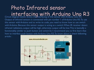
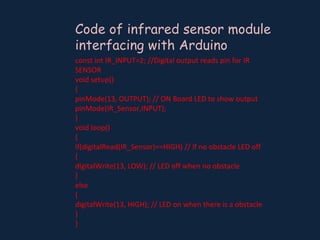
IR Sensors
Mechanism And
Interfacing With A
Micro-Controllers
Presented By
Khairun Nesa
MCSE(13114004)
University of Asia Pacific
Submitted to:
Professor Abdul Hamid Sir
A sensor is a device which is used to sense the
surroundings of it & gives some useful information
about it.
This information is used based on our
requirement.
An electronic sensor gives the information by
giving some electronic signal.
This information is used to perform a given task
which needs interaction with the surroundings.
What is a Sensor?
WHAT IS AN IR
SENSOR
 An IR sensor is a device which detects
IR radiation falling on it.
 The band of light which is a thousand
times wider than that of a visible light is
defined as Infrared light.
 Physically, light with wavelength from
0.7 m to 0.1 mm is called Infraredμ
Light.As our eyes cannot see the light
with wavelength longer than 7 × 10⁻⁵
m, thus IR light is invisible to theμ
human.
 These types of radiations are invisible
to our eyes, that can be detected by an
infrared sensor.
Different Types of IR
Sensors and Their Applications
 IR sensors are classified into different types depending on the applications.
 RadiationThermometers: IR sensors are used in radiation thermometers
to measure the temperature depend upon the temperature
 Flame Monitors: These types of devices are used for detecting the light
emitted from the flames and to monitor how the flames are burning.The
Light emitted from flames extend from UV to IR region types.
 Proximity sensors (Used inTouch Screen phones and Edge Avoiding
Robots), Contrast sensors (Used in Line Following Robots)
 Gas Analyzers: IR sensors are used in gas analyzers which use absorption
characteristics of gases in the IR region. The temperature sensor is used
for industrial temperature control.
 PIR sensor is used for automatic door opening system.
IR Imaging Devices
IR image device is one of the major applications of IR waves, primarily by virtue of
its property that is not visible. It is used for thermal imagers, night vision devices,
etc.
For examples Water, rocks, soil, vegetation, an atmosphere, and
human tissue all features emit IR radiation.
http://www.elprocus.com/
IR Sensor Circuit
 An infrared sensor circuit is one of the basic and popular sensor module in an
electronic device. This sensor is analogous to human’s visionary senses, which
can be used to detect obstacles and it is one of the common applications in real
time. This circuit comprises of the following components
 LM358 IC 2 IR transmitter and receiver pair.
 Resistors of the range of kilo ohms.
 Variable resistors.
 LED (Light Emitting Diode).
 Photodiode
Infrared IR Sensor Circuit
Diagram and Working Principle
http://www.elprocus.com/
Infrared IR Sensor
Circuit Diagram and Working
Principle
IR Sensor Board
Infrared IR Sensor Circuit
Diagram and Working Mechanism
 An IR LED is a type of LED which emits light in
the frequency range of Infra-Red, hence the
name
 A photodiode is a type of diode which
detects light.We can think of it as having a
very high resistance when no light is falling
on it.
 Variable Resistor:
A variale resistor is a 3 pin device which is used
to vary resistance. In this circuit, we use it to calibrate
the IR sensor according to the environment.We giveVcc
and GND to the terminals which are close together and
connect the center terminal to the threshold of the IC
HARDWARE DESCRIPTION
 IC Op-Amp LM358M (as a voltage comparator :LM358M is a general
purpose Dual Operational Amplifier (Op-Amp). So basically, we use it
to compare two voltages, one is fixed and the other varies with an
environmental parameter.This IC is an 8 pin IC. Check the illustration
above for the pin layout. Output (pin 1) is where we get the 5/0Volts,
Threshold (pin 2) is the fixed voltage, Input (pin 3) is where we
supply our environment controlled voltage, and pin 4 & 8 are used to
power up the IC.The best part about this IC is that it is a Dual Op-
Amp, so you can make two completely separate IR sensors using the
same IC! All you need to do is mirror all the connections on the
lower three terminals of the other half of the IC (Refer to the pin
diagram of the IC).
ared IR Sensor Circuit Diagram and Working Mec
IR Sensor Circuit Breaker Diagram
http://www.elprocus.com/
Working
Principle of IR Sensor
 When the IR receiver does not receive a signal
 The potential at the inverting input goes higher than that non-inverting
input of the comparator IC (LM339).
 Thus the output of the comparator goes low, but the LED does not glow.
 When the IR receiver module receives signal to the potential at the
inverting input goes low.
http://www.elprocus.com/
Working Principle of IR
Sensor
 Thus the output of the comparator (LM 339) goes high and the LED
starts glowing.
 Resistor R1 (10), R2 (10k ) and R3 (150) are used to ensure that
minimum 10 mA current passes through the IR LED Devices like
Photodiode and normal LEDs respectively.
 ResistorVR2 (preset=5k ) is used to adjust the output terminals.
 ResistorVR1 (preset=10k ) is used to set the sensitivity of the circuit
Diagram.
Photo Infrared sensor
interfacing with Arduino Uno R3Circuit diagram below shows the interfacing of this sensor with Arduino Uno R3.
Output of infrared sensors is connected with pin number 1 of Arduino Uno R3.To use
this sensor with Arduino and to write its code, you need to know how to use switch
with Arduino. Because this sensor output is acting as a switch.When IR receiver detect
infrared radiations, output will be high, otherwise output will be low.This is basically a
functionality similar to push button and switch.So I recommend you to first learn that
how to interface push button with Arduino Uno R3.To know about it check following
article :
Code of infrared sensor module
interfacing with Arduino
const int IR_INPUT=2; //Digital output reads pin for IR
SENSOR
void setup()
{
pinMode(13, OUTPUT); // ON Board LED to show output
pinMode(IR_Sensor,INPUT);
}
void loop()
{
if(digitalRead(IR_Sensor)==HIGH) // if no obstacle LED off
{
digitalWrite(13, LOW); // LED off when no obstacle
}
else
{
digitalWrite(13, HIGH); // LED on when there is a obstacle
}
}
Ir sensor mechanism and  interfacing with  a micro controllers.PPT

Ir sensor mechanism and interfacing with a micro controllers.PPT

  • 1.
    IR Sensors Mechanism And InterfacingWith A Micro-Controllers Presented By Khairun Nesa MCSE(13114004) University of Asia Pacific Submitted to: Professor Abdul Hamid Sir
  • 2.
    A sensor isa device which is used to sense the surroundings of it & gives some useful information about it. This information is used based on our requirement. An electronic sensor gives the information by giving some electronic signal. This information is used to perform a given task which needs interaction with the surroundings. What is a Sensor?
  • 3.
    WHAT IS ANIR SENSOR  An IR sensor is a device which detects IR radiation falling on it.  The band of light which is a thousand times wider than that of a visible light is defined as Infrared light.  Physically, light with wavelength from 0.7 m to 0.1 mm is called Infraredμ Light.As our eyes cannot see the light with wavelength longer than 7 × 10⁻⁵ m, thus IR light is invisible to theμ human.  These types of radiations are invisible to our eyes, that can be detected by an infrared sensor.
  • 4.
    Different Types ofIR Sensors and Their Applications  IR sensors are classified into different types depending on the applications.  RadiationThermometers: IR sensors are used in radiation thermometers to measure the temperature depend upon the temperature  Flame Monitors: These types of devices are used for detecting the light emitted from the flames and to monitor how the flames are burning.The Light emitted from flames extend from UV to IR region types.  Proximity sensors (Used inTouch Screen phones and Edge Avoiding Robots), Contrast sensors (Used in Line Following Robots)  Gas Analyzers: IR sensors are used in gas analyzers which use absorption characteristics of gases in the IR region. The temperature sensor is used for industrial temperature control.  PIR sensor is used for automatic door opening system.
  • 5.
    IR Imaging Devices IRimage device is one of the major applications of IR waves, primarily by virtue of its property that is not visible. It is used for thermal imagers, night vision devices, etc. For examples Water, rocks, soil, vegetation, an atmosphere, and human tissue all features emit IR radiation.
  • 6.
    http://www.elprocus.com/ IR Sensor Circuit An infrared sensor circuit is one of the basic and popular sensor module in an electronic device. This sensor is analogous to human’s visionary senses, which can be used to detect obstacles and it is one of the common applications in real time. This circuit comprises of the following components  LM358 IC 2 IR transmitter and receiver pair.  Resistors of the range of kilo ohms.  Variable resistors.  LED (Light Emitting Diode).  Photodiode Infrared IR Sensor Circuit Diagram and Working Principle
  • 7.
    http://www.elprocus.com/ Infrared IR Sensor CircuitDiagram and Working Principle IR Sensor Board
  • 8.
    Infrared IR SensorCircuit Diagram and Working Mechanism  An IR LED is a type of LED which emits light in the frequency range of Infra-Red, hence the name  A photodiode is a type of diode which detects light.We can think of it as having a very high resistance when no light is falling on it.  Variable Resistor: A variale resistor is a 3 pin device which is used to vary resistance. In this circuit, we use it to calibrate the IR sensor according to the environment.We giveVcc and GND to the terminals which are close together and connect the center terminal to the threshold of the IC HARDWARE DESCRIPTION
  • 9.
     IC Op-AmpLM358M (as a voltage comparator :LM358M is a general purpose Dual Operational Amplifier (Op-Amp). So basically, we use it to compare two voltages, one is fixed and the other varies with an environmental parameter.This IC is an 8 pin IC. Check the illustration above for the pin layout. Output (pin 1) is where we get the 5/0Volts, Threshold (pin 2) is the fixed voltage, Input (pin 3) is where we supply our environment controlled voltage, and pin 4 & 8 are used to power up the IC.The best part about this IC is that it is a Dual Op- Amp, so you can make two completely separate IR sensors using the same IC! All you need to do is mirror all the connections on the lower three terminals of the other half of the IC (Refer to the pin diagram of the IC). ared IR Sensor Circuit Diagram and Working Mec
  • 10.
    IR Sensor CircuitBreaker Diagram
  • 11.
    http://www.elprocus.com/ Working Principle of IRSensor  When the IR receiver does not receive a signal  The potential at the inverting input goes higher than that non-inverting input of the comparator IC (LM339).  Thus the output of the comparator goes low, but the LED does not glow.  When the IR receiver module receives signal to the potential at the inverting input goes low.
  • 12.
    http://www.elprocus.com/ Working Principle ofIR Sensor  Thus the output of the comparator (LM 339) goes high and the LED starts glowing.  Resistor R1 (10), R2 (10k ) and R3 (150) are used to ensure that minimum 10 mA current passes through the IR LED Devices like Photodiode and normal LEDs respectively.  ResistorVR2 (preset=5k ) is used to adjust the output terminals.  ResistorVR1 (preset=10k ) is used to set the sensitivity of the circuit Diagram.
  • 13.
    Photo Infrared sensor interfacingwith Arduino Uno R3Circuit diagram below shows the interfacing of this sensor with Arduino Uno R3. Output of infrared sensors is connected with pin number 1 of Arduino Uno R3.To use this sensor with Arduino and to write its code, you need to know how to use switch with Arduino. Because this sensor output is acting as a switch.When IR receiver detect infrared radiations, output will be high, otherwise output will be low.This is basically a functionality similar to push button and switch.So I recommend you to first learn that how to interface push button with Arduino Uno R3.To know about it check following article :
  • 14.
    Code of infraredsensor module interfacing with Arduino const int IR_INPUT=2; //Digital output reads pin for IR SENSOR void setup() { pinMode(13, OUTPUT); // ON Board LED to show output pinMode(IR_Sensor,INPUT); } void loop() { if(digitalRead(IR_Sensor)==HIGH) // if no obstacle LED off { digitalWrite(13, LOW); // LED off when no obstacle } else { digitalWrite(13, HIGH); // LED on when there is a obstacle } }