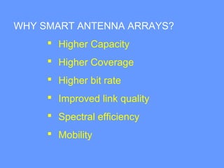
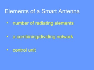
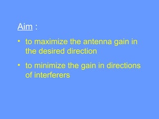
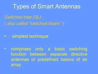
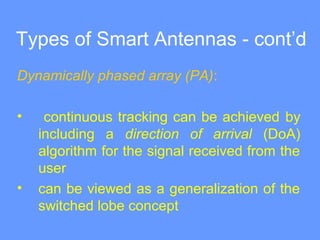
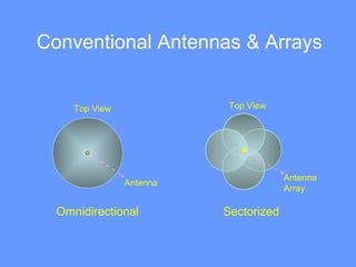
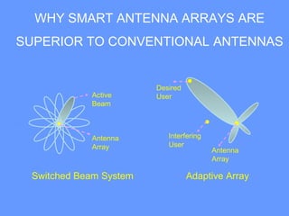
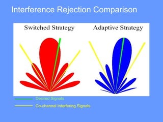
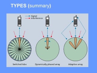
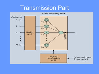
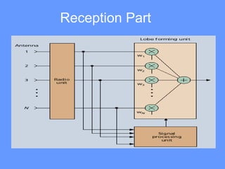
SMART ANTENNAS SYSTEM
Submitted to:- Submitted by:-
Er. Suman Rani Sanjay Sharma
Smart Antenna Array:
• antenna array with a digital signal
processing capability to transmit and
receive in an adaptive and spatially
sensitive manner.
“Smart” >> digital signal processing facility
USAGE
Applications to:
• cellular and wireless networks
• radar
• electronic warfare (EWF) as a
countermeasure to electronic
jamming
• satellite systems
WHY SMART ANTENNA ARRAYS?
 Higher Capacity
 Higher Coverage
 Higher bit rate
 Improved link quality
 Spectral efficiency
 Mobility
Elements of a Smart Antenna
• number of radiating elements
• a combining/dividing network
• control unit
Aim :
• to maximize the antenna gain in
the desired direction
• to minimize the gain in directions
of interferers
Types of Smart Antennas
Switched lobe (SL):
( also called “switched beam” )
• simplest technique
• comprises only a basic switching
function between separate directive
antennas or predefined beams of an
array
Types of Smart Antennas - cont’d
Dynamically phased array (PA):
• continuous tracking can be achieved by
including a direction of arrival (DoA)
algorithm for the signal received from the
user
• can be viewed as a generalization of the
switched lobe concept
Conventional Antennas & Arrays
Antenna
Top View
Antenna
Array
Top View
Omnidirectional Sectorized
WHY SMART ANTENNA ARRAYS ARE
SUPERIOR TO CONVENTIONAL ANTENNAS
Switched Beam System Adaptive Array
Antenna
Array
Desired
User
Interfering
User
Antenna
Array
Active
Beam
Interference Rejection Comparison
Desired Signals
Co-channel Interfering Signals
TYPES (summary)
Transmission Part
Reception Part
Smart Antennas for Base
Stations
• the idea of smart antennas is to
use base station antenna
patterns that are not fixed, but
adapt to the current radio
conditions
• can be visualized as the
antenna directing a beam toward
the communication partner only
SMDA
(Space Division Multiple Access)
• more than one user can be allocated to the
same physical communications channel
simultaneously in the same cell
• separated by angle only
• in a TDMA system, two users will be
allocated to the same time slot and carrier
frequency at the same time and in the same
cell
SDMA (Space Division Multiple Access)
Comparison of Switched Beam Antenna
Adaptive Arrays
Criteria Switched Beam Adaptive Array
Integration • Easy to implement
• Low cost
• Transceiver complexity
• High cost
• Less hardware
redundancy
Range/
Coverage
• More coverage compared
to conventional systems
• Less coverage compared to
adaptive array
More coverage compared
to switched beam system
Interference
Rejection
• Difficulty in distinguishing
between desired signal and
interferer
• Does not react to the
movement of interferers.
• Focusing is narrower
• Capable of nulling
interfering signals
REFERENCES
1. “Smart Antenna Systems Tutorial”, The International Engineering
Consortium, http://www.iec.org/online/tutorials/smart_ant/
2. Lehne, P.H. and Pettersen M., “An Overview of Smart Antenna
Technology for Mobile Communications Systems”, IEE
Communications Surveys, Fourth Quarter 1999, vol. 2, no.4,
http://www.comsoc.org/livepubs/surveys/public/4q99issue/pdf/Lehne.pdf
3. Schüttengruber, W., Molisch A.F. and Bonek E., “Smart Antennas for
Mobile Communications Tutorial”,
http://www.nt.tuwien.ac.at/mobile/research/smart_antennas_tutorial/inde
x.en.html
4. “Smart Antennas Tutorial,” http://viterbi.ece.iisc.ernet.in/prem/SmartAnt/
5. “Smart Antennas – A Non-technical Introduction”, SYMENA Software &
Consulting GmbH, http://www.symena.com/Smart Antennas - A
Nontechnical Introduction - SYMENA.pdf

ppt on Smart antennas

  • 1.
    SMART ANTENNAS SYSTEM Submittedto:- Submitted by:- Er. Suman Rani Sanjay Sharma
  • 2.
    Smart Antenna Array: •antenna array with a digital signal processing capability to transmit and receive in an adaptive and spatially sensitive manner. “Smart” >> digital signal processing facility
  • 3.
    USAGE Applications to: • cellularand wireless networks • radar • electronic warfare (EWF) as a countermeasure to electronic jamming • satellite systems
  • 4.
    WHY SMART ANTENNAARRAYS?  Higher Capacity  Higher Coverage  Higher bit rate  Improved link quality  Spectral efficiency  Mobility
  • 5.
    Elements of aSmart Antenna • number of radiating elements • a combining/dividing network • control unit
  • 6.
    Aim : • tomaximize the antenna gain in the desired direction • to minimize the gain in directions of interferers
  • 7.
    Types of SmartAntennas Switched lobe (SL): ( also called “switched beam” ) • simplest technique • comprises only a basic switching function between separate directive antennas or predefined beams of an array
  • 8.
    Types of SmartAntennas - cont’d Dynamically phased array (PA): • continuous tracking can be achieved by including a direction of arrival (DoA) algorithm for the signal received from the user • can be viewed as a generalization of the switched lobe concept
  • 9.
    Conventional Antennas &Arrays Antenna Top View Antenna Array Top View Omnidirectional Sectorized
  • 10.
    WHY SMART ANTENNAARRAYS ARE SUPERIOR TO CONVENTIONAL ANTENNAS Switched Beam System Adaptive Array Antenna Array Desired User Interfering User Antenna Array Active Beam
  • 11.
    Interference Rejection Comparison DesiredSignals Co-channel Interfering Signals
  • 12.
  • 13.
  • 14.
  • 15.
    Smart Antennas forBase Stations • the idea of smart antennas is to use base station antenna patterns that are not fixed, but adapt to the current radio conditions • can be visualized as the antenna directing a beam toward the communication partner only
  • 16.
    SMDA (Space Division MultipleAccess) • more than one user can be allocated to the same physical communications channel simultaneously in the same cell • separated by angle only • in a TDMA system, two users will be allocated to the same time slot and carrier frequency at the same time and in the same cell
  • 17.
    SDMA (Space DivisionMultiple Access)
  • 18.
    Comparison of SwitchedBeam Antenna Adaptive Arrays Criteria Switched Beam Adaptive Array Integration • Easy to implement • Low cost • Transceiver complexity • High cost • Less hardware redundancy Range/ Coverage • More coverage compared to conventional systems • Less coverage compared to adaptive array More coverage compared to switched beam system Interference Rejection • Difficulty in distinguishing between desired signal and interferer • Does not react to the movement of interferers. • Focusing is narrower • Capable of nulling interfering signals
  • 19.
    REFERENCES 1. “Smart AntennaSystems Tutorial”, The International Engineering Consortium, http://www.iec.org/online/tutorials/smart_ant/ 2. Lehne, P.H. and Pettersen M., “An Overview of Smart Antenna Technology for Mobile Communications Systems”, IEE Communications Surveys, Fourth Quarter 1999, vol. 2, no.4, http://www.comsoc.org/livepubs/surveys/public/4q99issue/pdf/Lehne.pdf 3. Schüttengruber, W., Molisch A.F. and Bonek E., “Smart Antennas for Mobile Communications Tutorial”, http://www.nt.tuwien.ac.at/mobile/research/smart_antennas_tutorial/inde x.en.html 4. “Smart Antennas Tutorial,” http://viterbi.ece.iisc.ernet.in/prem/SmartAnt/ 5. “Smart Antennas – A Non-technical Introduction”, SYMENA Software & Consulting GmbH, http://www.symena.com/Smart Antennas - A Nontechnical Introduction - SYMENA.pdf