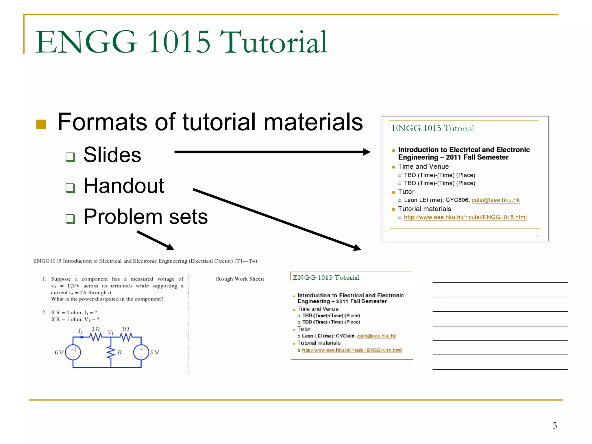
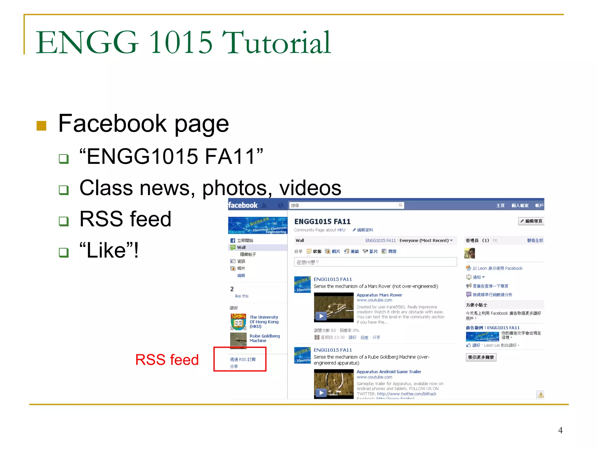
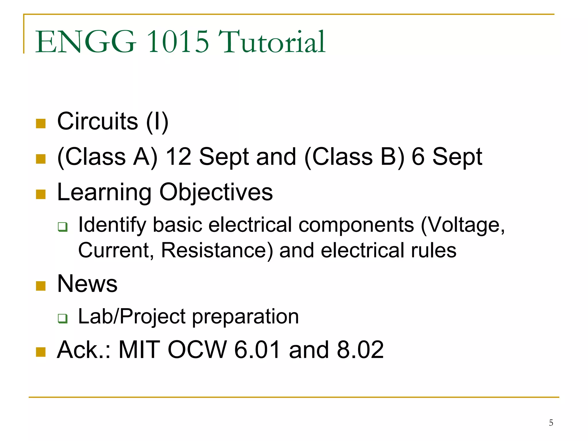
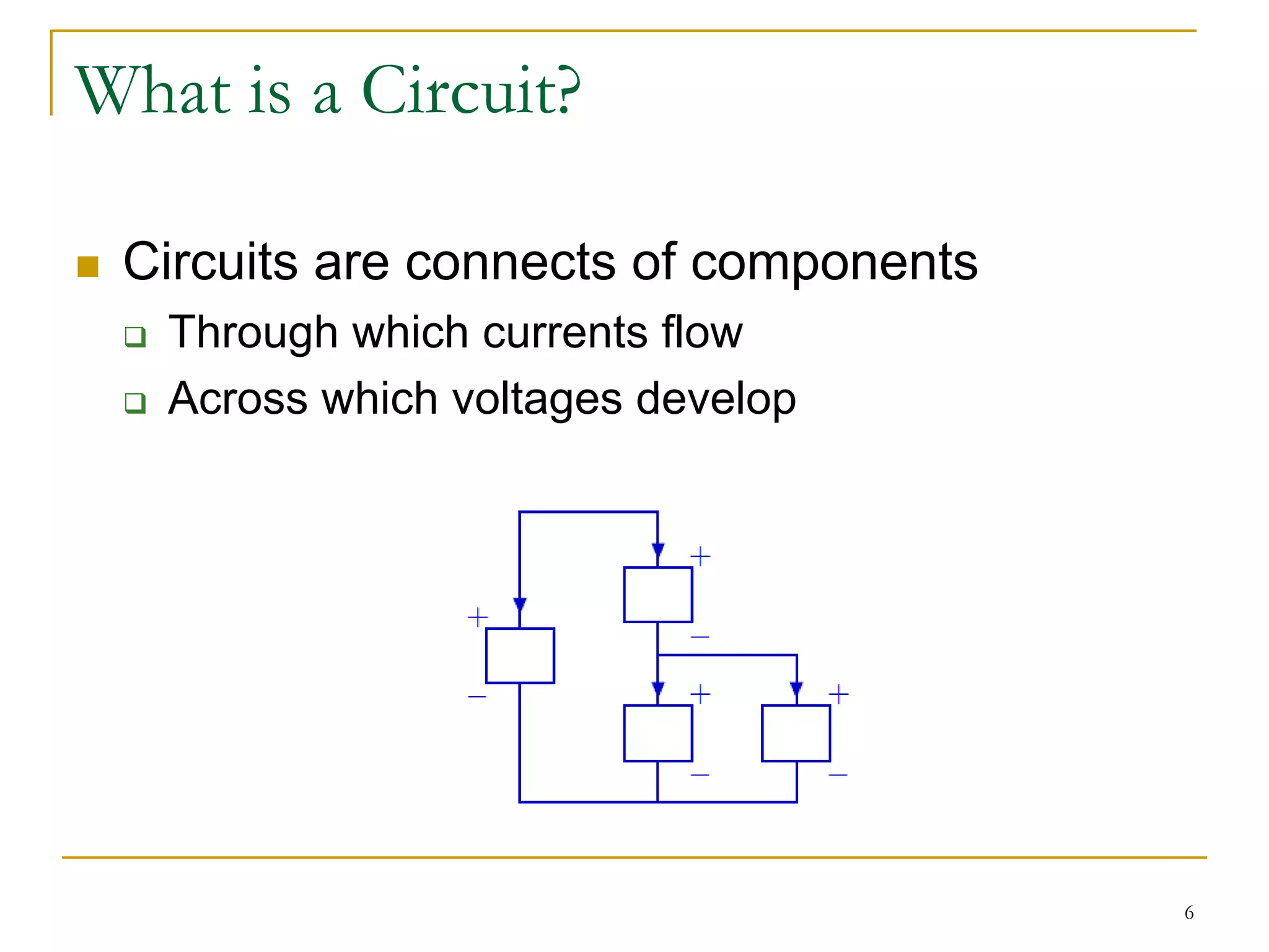
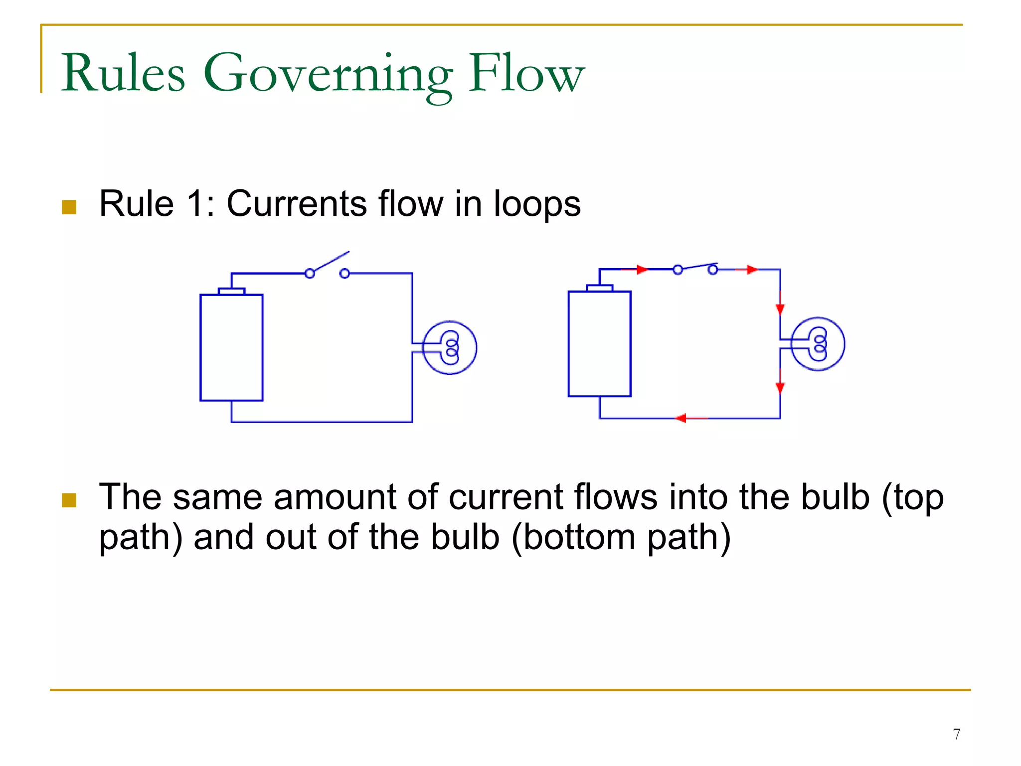
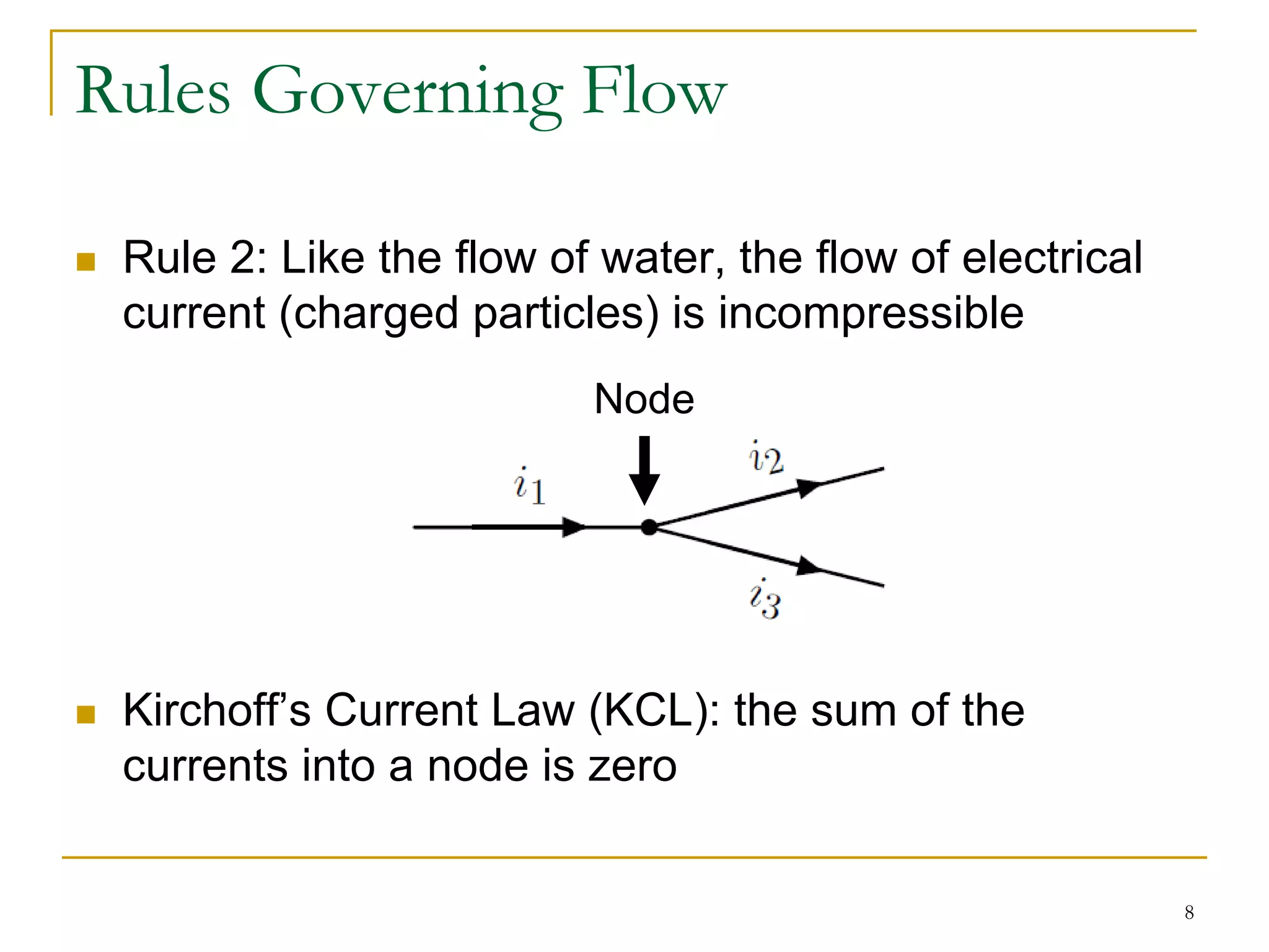
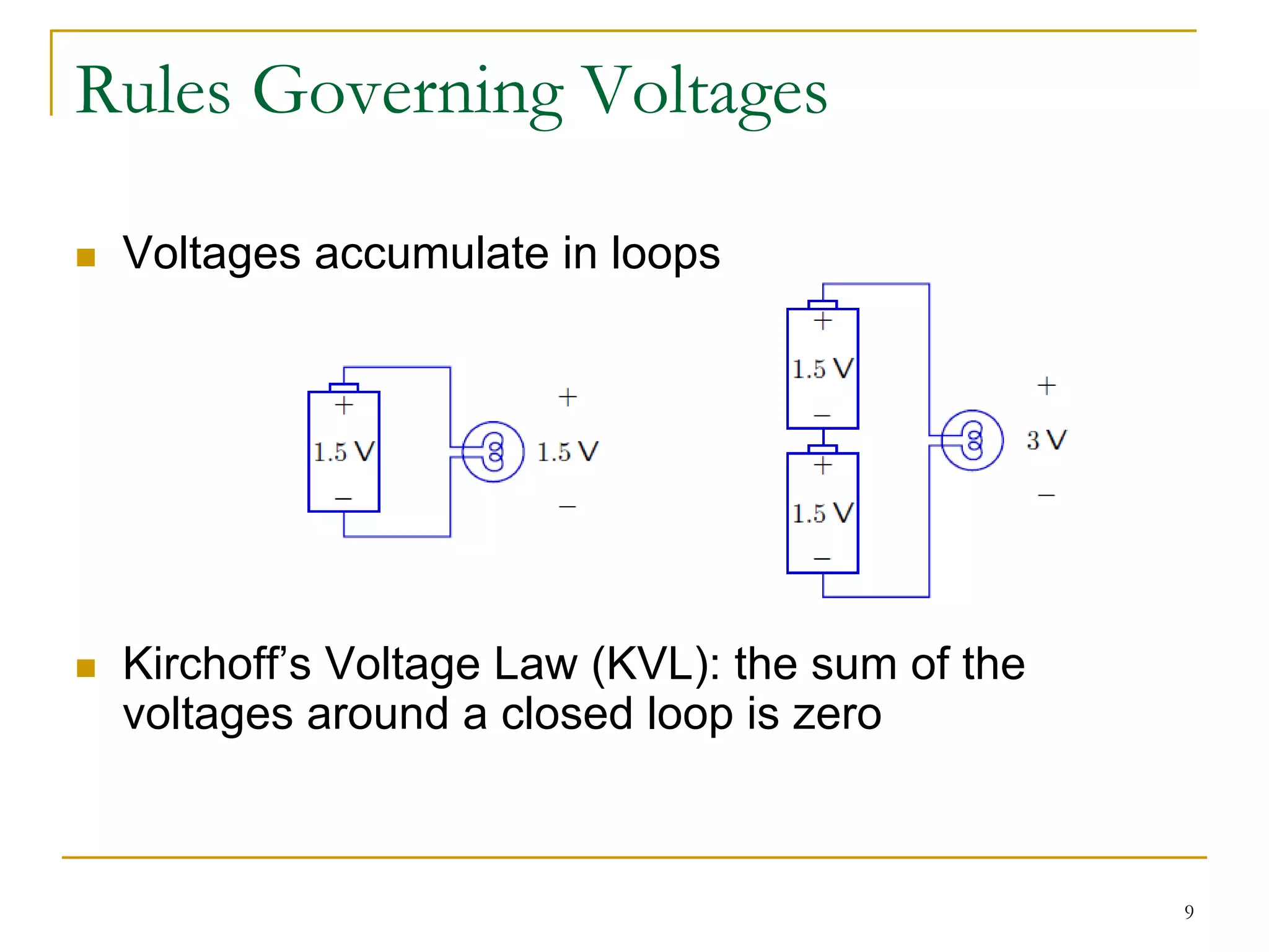
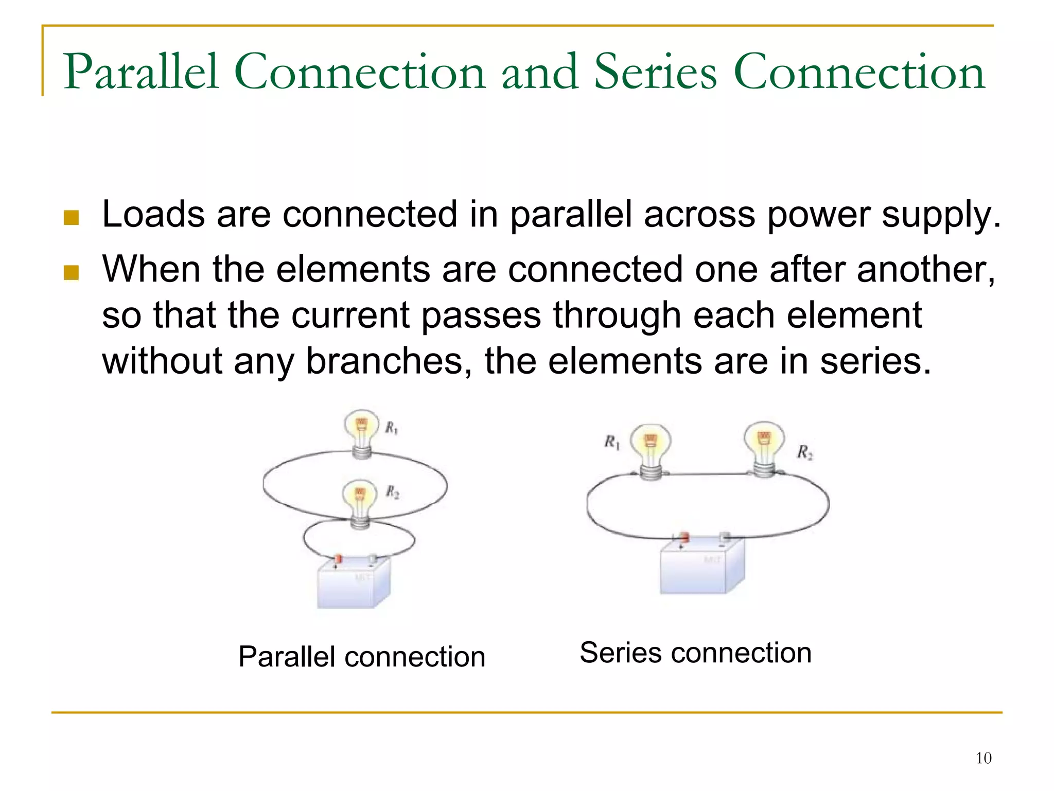
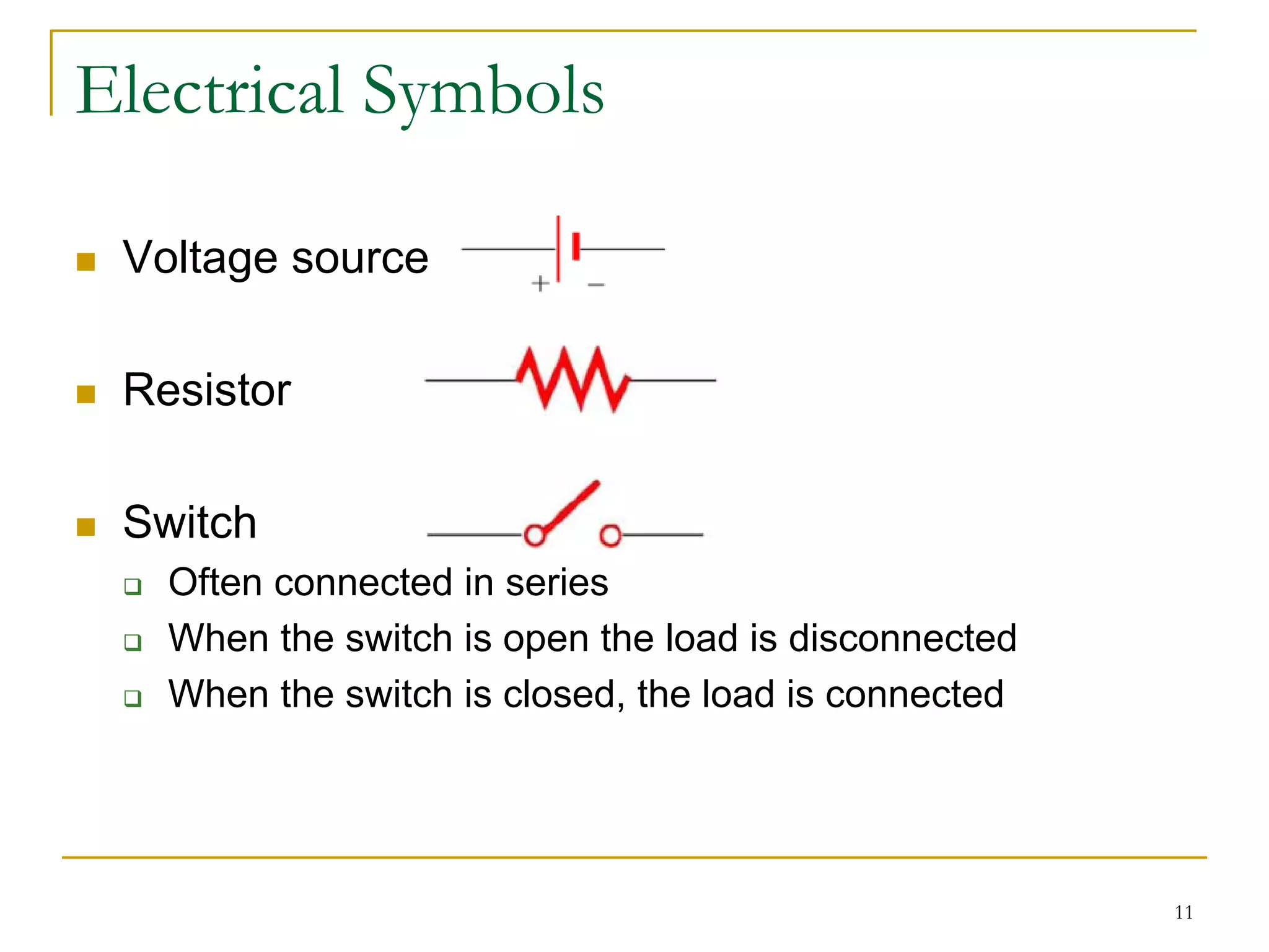
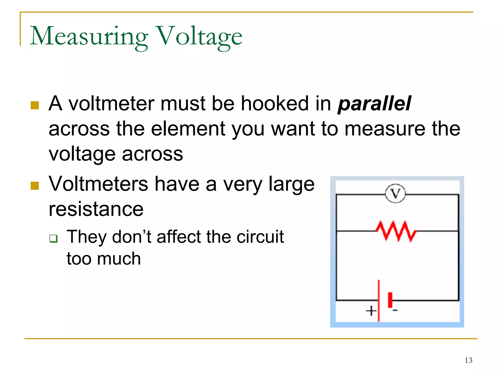
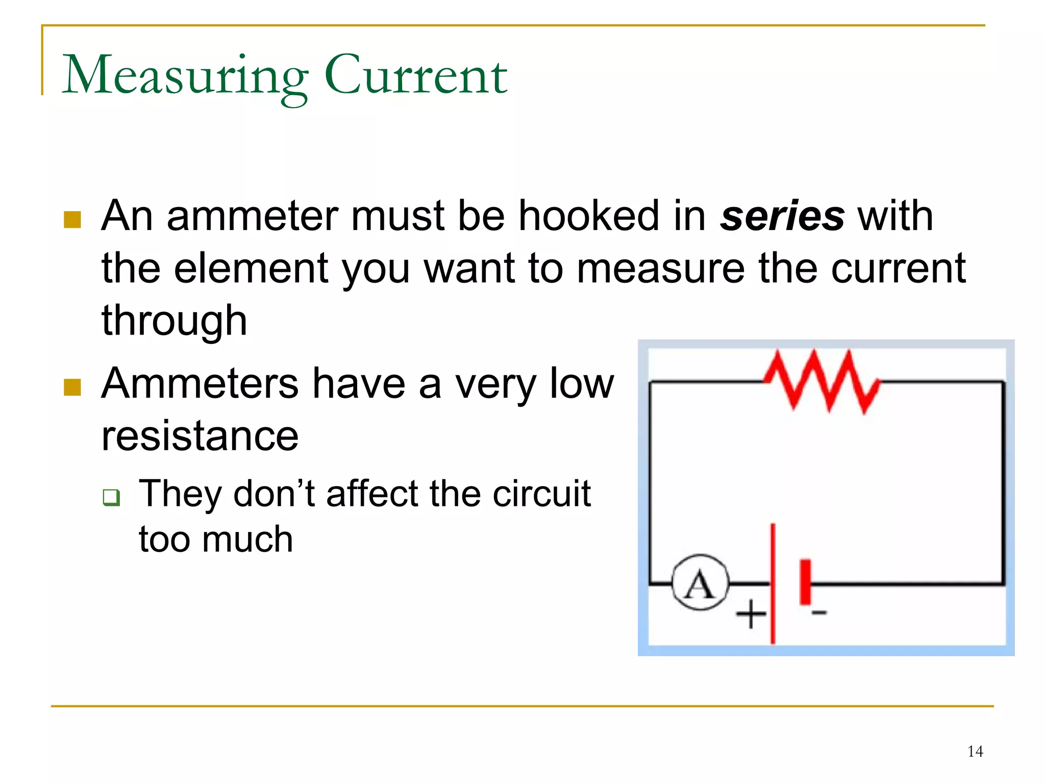
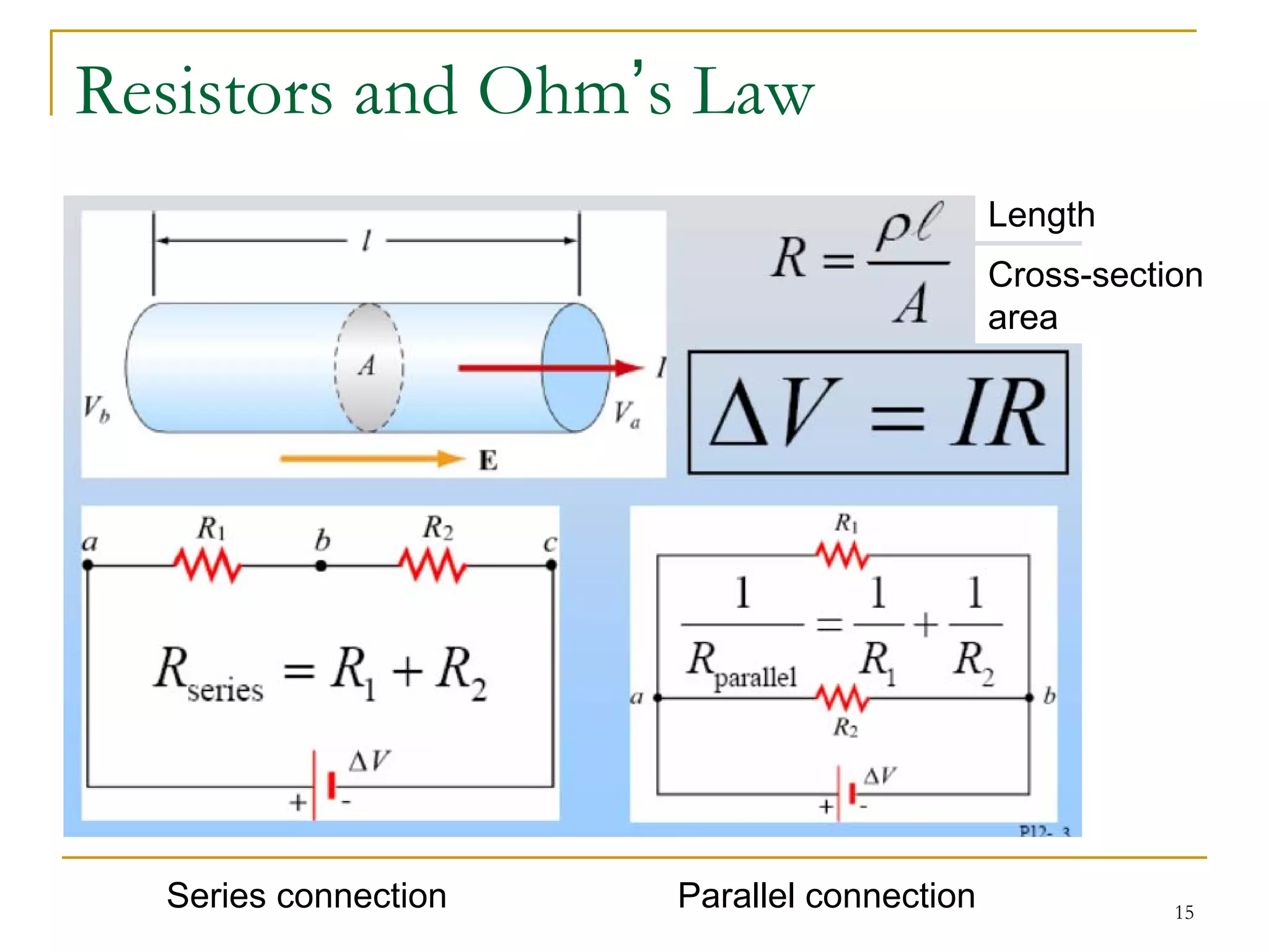
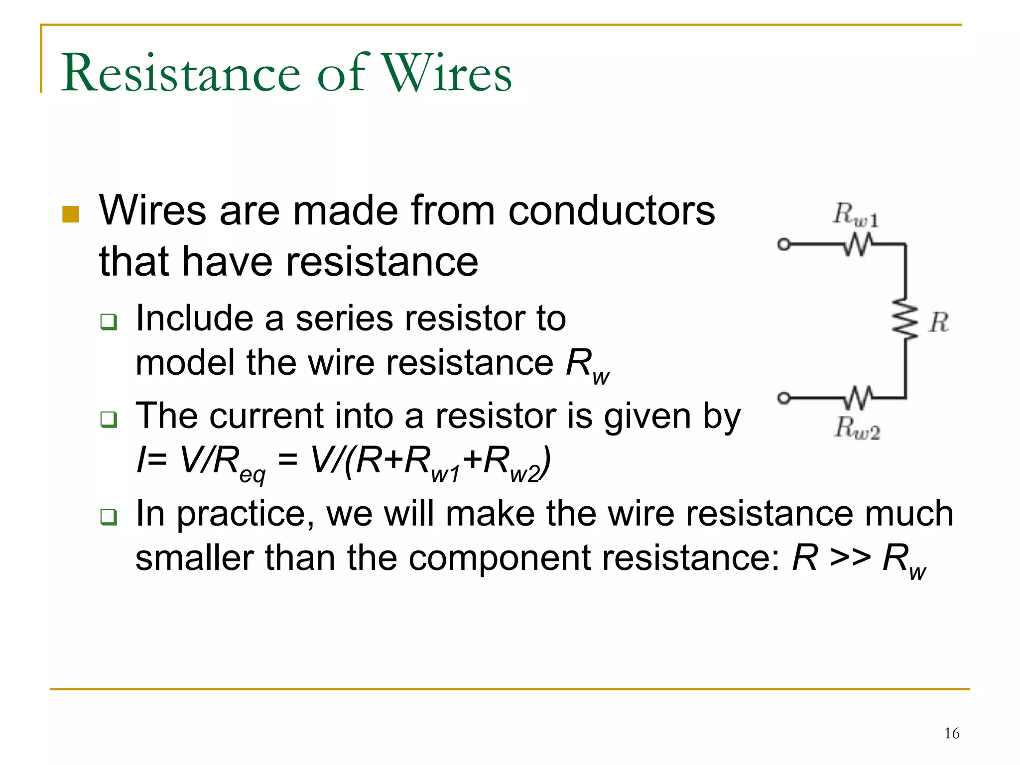
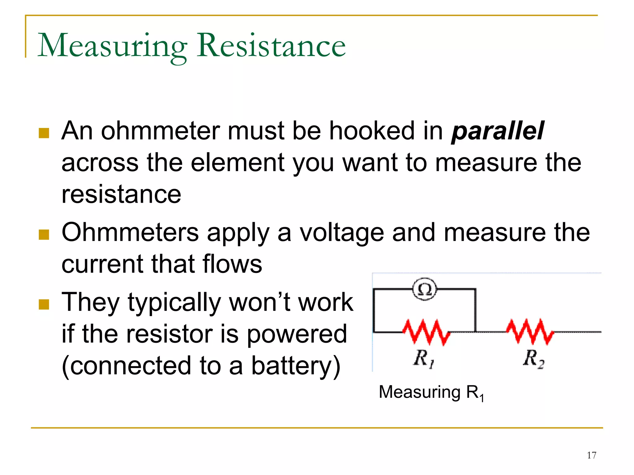
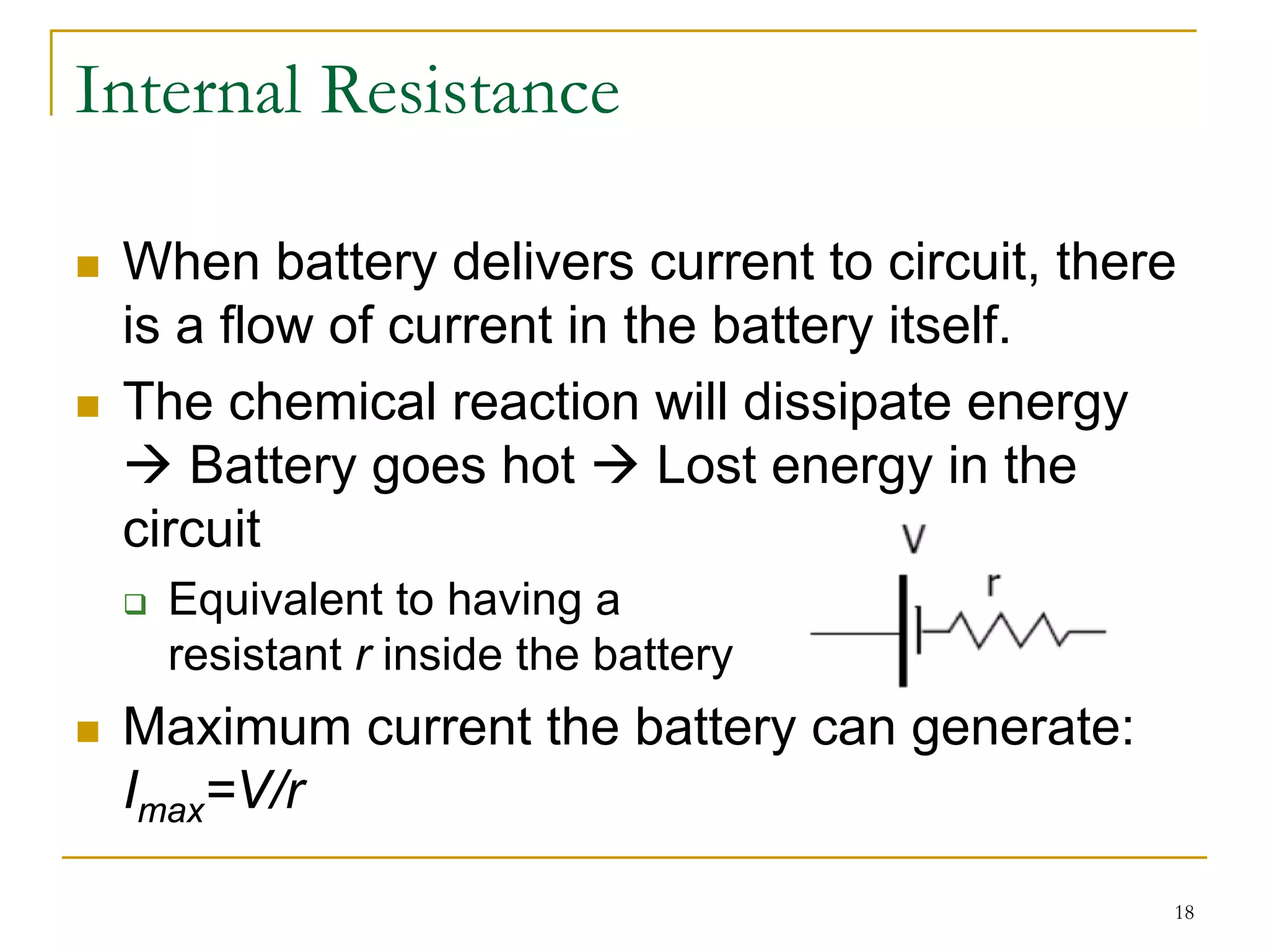
ENGG 1015 Tutorial

 Introduction to Electrical and Electronic
 Engineering – 2011 Fall Semester
 Time and Venue
   Class A: 1300-1355 MB201
   Class B: 1130-1225 CYC-C
 Tutor
   Leon LEI (me): CYC806, engg1015-staff@eee.hku.hk
 Tutorial materials
   http://www.eee.hku.hk/~culei/ENGG1015.html


                                                      1
ENGG 1015 Tutorial

 Each class: 40 min. tutorial + 15 min. Q/A
   Allow “no/low” voice discussion
   Go outside for phone conversations
   Same contents for Class A and Class B
 Tutorial materials
   Regular tutorials
   Revision tutorial before examination (Tentatively)
   Question bank
     Solutions and Exemplars of last year homework
     Extra MCQs, Extra SQs
 No homework plagiarism

                                                        2
ENGG 1015 Tutorial

 Formats of tutorial materials
   Slides
   Handout
   Problem sets


                                 3
ENGG 1015 Tutorial

 Facebook page
  “ENGG1015 FA11”
  Class news, photos, videos
  RSS feed
  “Like”!


       RSS feed


                               4
ENGG 1015 Tutorial

 Circuits (I)
 (Class A) 12 Sept and (Class B) 6 Sept
 Learning Objectives
  Identify basic electrical components (Voltage,
  Current, Resistance) and electrical rules
 News
  Lab/Project preparation
 Ack.: MIT OCW 6.01 and 8.02

                                                   5
What is a Circuit?

 Circuits are connects of components
   Through which currents flow
   Across which voltages develop


                                       6
Rules Governing Flow

 Rule 1: Currents flow in loops


 The same amount of current flows into the bulb (top
 path) and out of the bulb (bottom path)


                                                       7
Rules Governing Flow

 Rule 2: Like the flow of water, the flow of electrical
 current (charged particles) is incompressible
                         Node


 Kirchoff’s Current Law (KCL): the sum of the
 currents into a node is zero


                                                          8
Rules Governing Voltages

 Voltages accumulate in loops


 Kirchoff’s Voltage Law (KVL): the sum of the
 voltages around a closed loop is zero


                                                9
Parallel Connection and Series Connection

 Loads are connected in parallel across power supply.
 When the elements are connected one after another,
 so that the current passes through each element
 without any branches, the elements are in series.


        Parallel connection   Series connection


                                                   10
Electrical Symbols

 Voltage source

 Resistor

 Switch
   Often connected in series
   When the switch is open the load is disconnected
   When the switch is closed, the load is connected


                                                      11
Power Supply

 http://ocw.mit.edu/courses/physics/8-02-
 electricity-and-magnetism-spring-2002/video-
 lectures/lecture-10-batteries-and-emf/ or
 http://www.youtube.com/watch?v=RQX8I9Z
 WtPQ
 Definition and explanation of a battery
  4:11 minutes (0:00 - 4:11)
 Symbol for a battery in a circuit diagram
  Definition of internal resistance
  3:34 minutes (7:16 - 10:50)

                                             12
Measuring Voltage

 A voltmeter must be hooked in parallel
 across the element you want to measure the
 voltage across
 Voltmeters have a very large
 resistance
  They don’t affect the circuit
  too much


                                              13
Measuring Current

 An ammeter must be hooked in series with
 the element you want to measure the current
 through
 Ammeters have a very low
 resistance
  They don’t affect the circuit
  too much


                                               14
Resistors and Ohm’s Law
                                            Length
                                            Cross-section
                                            area


  Series connection   Parallel connection              15
Resistance of Wires

 Wires are made from conductors
 that have resistance
   Include a series resistor to
   model the wire resistance Rw
   The current into a resistor is given by
   I= V/Req = V/(R+Rw1+Rw2)
   In practice, we will make the wire resistance much
   smaller than the component resistance: R >> Rw


                                                    16
Measuring Resistance

 An ohmmeter must be hooked in parallel
 across the element you want to measure the
 resistance
 Ohmmeters apply a voltage and measure the
 current that flows
 They typically won’t work
 if the resistor is powered
 (connected to a battery)
                          Measuring R1


                                          17
Internal Resistance

 When battery delivers current to circuit, there
 is a flow of current in the battery itself.
 The chemical reaction will dissipate energy
    Battery goes hot       Lost energy in the
 circuit
   Equivalent to having a
   resistant r inside the battery
 Maximum current the battery can generate:
 Imax=V/r

                                               18
Demonstration: Batteries in Series

 http://ocw.mit.edu/courses/physics/8-02-
 electricity-and-magnetism-spring-2002/video-
 lectures/lecture-10-batteries-and-emf/ or
 http://www.youtube.com/watch?v=RQX8I9Z
 WtPQ
 Connecting two batteries in series
   4:30 minutes (10:50 - 15:20)


                                            19
Quick Checking

 Resistors and Ohm’s Law
  Ohm’s Law is XXX
 Measure Voltage & Current
  An ammeter must be hooked in XXX
 Internal Resistance of Battery
  Equivalent circuit of a non-ideal battery is XXX


                                                     20
Quick Checking

 Resistors and Ohm’s Law
  Ohm’s Law is “V=IR”
 Measure Voltage & Current
  An ammeter must be hooked in series
 Internal Resistance of Battery
  Equivalent circuit of a non-ideal battery is


                                                 21

ENGG1015 Tutorial 1

  • 1.
    ENGG 1015 Tutorial Introduction to Electrical and Electronic Engineering – 2011 Fall Semester Time and Venue Class A: 1300-1355 MB201 Class B: 1130-1225 CYC-C Tutor Leon LEI (me): CYC806, engg1015-staff@eee.hku.hk Tutorial materials http://www.eee.hku.hk/~culei/ENGG1015.html 1
  • 2.
    ENGG 1015 Tutorial Each class: 40 min. tutorial + 15 min. Q/A Allow “no/low” voice discussion Go outside for phone conversations Same contents for Class A and Class B Tutorial materials Regular tutorials Revision tutorial before examination (Tentatively) Question bank Solutions and Exemplars of last year homework Extra MCQs, Extra SQs No homework plagiarism 2
  • 3.
    ENGG 1015 Tutorial Formats of tutorial materials Slides Handout Problem sets 3
  • 4.
    ENGG 1015 Tutorial Facebook page “ENGG1015 FA11” Class news, photos, videos RSS feed “Like”! RSS feed 4
  • 5.
    ENGG 1015 Tutorial Circuits (I) (Class A) 12 Sept and (Class B) 6 Sept Learning Objectives Identify basic electrical components (Voltage, Current, Resistance) and electrical rules News Lab/Project preparation Ack.: MIT OCW 6.01 and 8.02 5
  • 6.
    What is aCircuit? Circuits are connects of components Through which currents flow Across which voltages develop 6
  • 7.
    Rules Governing Flow Rule 1: Currents flow in loops The same amount of current flows into the bulb (top path) and out of the bulb (bottom path) 7
  • 8.
    Rules Governing Flow Rule 2: Like the flow of water, the flow of electrical current (charged particles) is incompressible Node Kirchoff’s Current Law (KCL): the sum of the currents into a node is zero 8
  • 9.
    Rules Governing Voltages Voltages accumulate in loops Kirchoff’s Voltage Law (KVL): the sum of the voltages around a closed loop is zero 9
  • 10.
    Parallel Connection andSeries Connection Loads are connected in parallel across power supply. When the elements are connected one after another, so that the current passes through each element without any branches, the elements are in series. Parallel connection Series connection 10
  • 11.
    Electrical Symbols Voltagesource Resistor Switch Often connected in series When the switch is open the load is disconnected When the switch is closed, the load is connected 11
  • 12.
    Power Supply http://ocw.mit.edu/courses/physics/8-02- electricity-and-magnetism-spring-2002/video- lectures/lecture-10-batteries-and-emf/ or http://www.youtube.com/watch?v=RQX8I9Z WtPQ Definition and explanation of a battery 4:11 minutes (0:00 - 4:11) Symbol for a battery in a circuit diagram Definition of internal resistance 3:34 minutes (7:16 - 10:50) 12
  • 13.
    Measuring Voltage Avoltmeter must be hooked in parallel across the element you want to measure the voltage across Voltmeters have a very large resistance They don’t affect the circuit too much 13
  • 14.
    Measuring Current Anammeter must be hooked in series with the element you want to measure the current through Ammeters have a very low resistance They don’t affect the circuit too much 14
  • 15.
    Resistors and Ohm’sLaw Length Cross-section area Series connection Parallel connection 15
  • 16.
    Resistance of Wires Wires are made from conductors that have resistance Include a series resistor to model the wire resistance Rw The current into a resistor is given by I= V/Req = V/(R+Rw1+Rw2) In practice, we will make the wire resistance much smaller than the component resistance: R >> Rw 16
  • 17.
    Measuring Resistance Anohmmeter must be hooked in parallel across the element you want to measure the resistance Ohmmeters apply a voltage and measure the current that flows They typically won’t work if the resistor is powered (connected to a battery) Measuring R1 17
  • 18.
    Internal Resistance Whenbattery delivers current to circuit, there is a flow of current in the battery itself. The chemical reaction will dissipate energy Battery goes hot Lost energy in the circuit Equivalent to having a resistant r inside the battery Maximum current the battery can generate: Imax=V/r 18
  • 19.
    Demonstration: Batteries inSeries http://ocw.mit.edu/courses/physics/8-02- electricity-and-magnetism-spring-2002/video- lectures/lecture-10-batteries-and-emf/ or http://www.youtube.com/watch?v=RQX8I9Z WtPQ Connecting two batteries in series 4:30 minutes (10:50 - 15:20) 19
  • 20.
    Quick Checking Resistorsand Ohm’s Law Ohm’s Law is XXX Measure Voltage & Current An ammeter must be hooked in XXX Internal Resistance of Battery Equivalent circuit of a non-ideal battery is XXX 20
  • 21.
    Quick Checking Resistorsand Ohm’s Law Ohm’s Law is “V=IR” Measure Voltage & Current An ammeter must be hooked in series Internal Resistance of Battery Equivalent circuit of a non-ideal battery is 21