Electricity
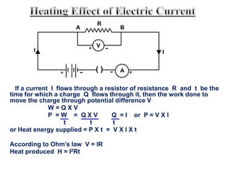
Electricity is a form of energy that can be
easily changed to other forms.
Electric current is the flow of electrons through a conductor.
The device which causes the flow of electrons through a conductor is
called a cell.
Electrons flow from the negative terminal to the positive terminal.
Electric current flows from the positive terminal to the negative terminal.
This is called conventional current.
Electric current is expressed as :-
The rate of flow of charges through a
conductor or the quantity of charges flowing through a conductor in
unit time.
I = Q/t
I – current, Q – quantity of charge, t – time
• Electric Circuit is a continuous and closed path of an
electric current.
A schematic diagram of an electric circuit comprising
of a cell, electric bulb, ammeter and plug key.
A
+
-
+-
bulb
cell
ammeter
plug key
Electric circuits are
made up of electrical
components
These components
must be joined
together without any
gap in between to
form a closed circuit.
connecting wires
electric cell
circuit boardlight bulb
NOTE:
Components refer to the light bulb, wires, battery
• Incomplete circuits are called open circuits.
connecting wire is
missing
no source of
electrical energy
Both the circuits in the diagram are incomplete, hence they are known as
“open circuits”.
An electric currentflows only when there is:
• a source of electrical energy and
• a closed circuit
connecting wires
electric cell
circuit boardlight bulb
How to draw Circuit Diagrams
Component Symbol Component Symbol
An electric cell Battery
Light bulb (lamp) Switch
Switch (open)
Switch (closed)
Connecting wires
(not joined)
Connecting wires
(joined)
+ +
Symbols are used to represent the various electrical components
in circuits.
Symbols of components used in electric circuits :-
An electric cell A battery or combination
of cells
Plug key or switch Plug key or switch
(open) (closed)
Electric bulb A resistor of
resistance R
Variable resistance or
or rheostat
Ammeter Voltmeter
A wire joint A wire crossing over
without joining
A v
+ - -+
+ - + -
There are 2 ways inwhichan electric circuit can
be arranged:
1. Series
2. Parallel
Series Circuit
• A series circuit connects the components one after
the other
• A single loop is formed
• A break in any part of a series circuit stops the flow
of current in the whole circuit.
Resistors in Series
• Whenresistors are
connected in series, the
resistance will add up and
increase.
• R = R1 + R2 + R3…
2  3 
The total resistance for this circuit is:
2  + 3  = 5 
Parallel Circuit
• A parallel circuit divides into two or more branches.
• The current divides and flows through each parallel
branch.
• If a component breaks or is removed, the other
components remain on.
• When resistors are connected
in parallel, the resistance will
decrease
• This is because they will
provide alternate routes for
the current to flow.
Resistors in Parallel
S/E: Resistors in Parallel
6 
6 
1
R
=
1
R
1
R
1
R
+ +
1 2 3
What is the resistance of the
circuit?
1
R
=
1
6
1
6
+
1
R
=
2
6
1
3
= R = 3 The final resistance
is smaller
• When an electric current flows through a wire, the wire heats up.
Electrical energy has been converted into heat energy.
• The greater the resistance of the wire, the greater the amount of
heat produced. This heating effect is used in common electrical
appliances.
Iron Kettle Hair Dryer
A kettle uses both copper and nichrome wires.
Copper has low resistance while nichrome has high resistance.
Which material, copper or nichrome, should be used for the heating element,
and for the external wire?
Use copper wire for
the external wire as it
has low resistance &
produces less heat
Use nichrome wire for the heating element
as it has high resistance& produces a lot
of heat
filament wire produces
heat and light
In a light bulb, the heated filament
which is also a resistancewire,
becomes so hot that light is also
emitted.
ARGON (inert/unreactive gas)
If a current I flows through a resistor of resistance R and t be the
time for which a charge Q flows through it, then the work done to
move the charge through potential difference V
W = Q X V
P = W = Q X V Q = I or P = V X I
t t t
or Heat energy supplied = P X t = V X I X t
According to Ohm’s law V = IR
Heat produced H = I2Rt
( ) A
V
R
A B
I I
+ -
+ -
+-
When electric charges move through a wire, they
lose some of the energy to the atoms in the wire. On
receiving the energy, The atoms vibrate more and
more causing the wire to heat up. Some of the
Electric Energy is changed to Heat Energy. The
higher the resistance the more the heat energy.
 The amount of heat generated is governed by
Joule's first law:
Q = I2·R·t
 In industry Soldering, Welding, Cutting, Drilling
and Working of Electric Furnaces are based on
Heating of Electric Current.

Electricity

  • 1.
  • 2.
    Electricity is aform of energy that can be easily changed to other forms.
  • 3.
    Electric current isthe flow of electrons through a conductor. The device which causes the flow of electrons through a conductor is called a cell. Electrons flow from the negative terminal to the positive terminal. Electric current flows from the positive terminal to the negative terminal. This is called conventional current. Electric current is expressed as :- The rate of flow of charges through a conductor or the quantity of charges flowing through a conductor in unit time. I = Q/t I – current, Q – quantity of charge, t – time
  • 4.
    • Electric Circuitis a continuous and closed path of an electric current. A schematic diagram of an electric circuit comprising of a cell, electric bulb, ammeter and plug key. A + - +- bulb cell ammeter plug key
  • 5.
    Electric circuits are madeup of electrical components These components must be joined together without any gap in between to form a closed circuit. connecting wires electric cell circuit boardlight bulb NOTE: Components refer to the light bulb, wires, battery
  • 6.
    • Incomplete circuitsare called open circuits. connecting wire is missing no source of electrical energy Both the circuits in the diagram are incomplete, hence they are known as “open circuits”.
  • 7.
    An electric currentflowsonly when there is: • a source of electrical energy and • a closed circuit connecting wires electric cell circuit boardlight bulb
  • 8.
    How to drawCircuit Diagrams Component Symbol Component Symbol An electric cell Battery Light bulb (lamp) Switch Switch (open) Switch (closed) Connecting wires (not joined) Connecting wires (joined) + + Symbols are used to represent the various electrical components in circuits.
  • 9.
    Symbols of componentsused in electric circuits :- An electric cell A battery or combination of cells Plug key or switch Plug key or switch (open) (closed) Electric bulb A resistor of resistance R Variable resistance or or rheostat Ammeter Voltmeter A wire joint A wire crossing over without joining A v + - -+ + - + -
  • 10.
    There are 2ways inwhichan electric circuit can be arranged: 1. Series 2. Parallel
  • 11.
    Series Circuit • Aseries circuit connects the components one after the other • A single loop is formed • A break in any part of a series circuit stops the flow of current in the whole circuit.
  • 12.
    Resistors in Series •Whenresistors are connected in series, the resistance will add up and increase. • R = R1 + R2 + R3… 2  3  The total resistance for this circuit is: 2  + 3  = 5 
  • 13.
    Parallel Circuit • Aparallel circuit divides into two or more branches. • The current divides and flows through each parallel branch. • If a component breaks or is removed, the other components remain on.
  • 14.
    • When resistorsare connected in parallel, the resistance will decrease • This is because they will provide alternate routes for the current to flow. Resistors in Parallel
  • 15.
    S/E: Resistors inParallel 6  6  1 R = 1 R 1 R 1 R + + 1 2 3 What is the resistance of the circuit? 1 R = 1 6 1 6 + 1 R = 2 6 1 3 = R = 3 The final resistance is smaller
  • 16.
    • When anelectric current flows through a wire, the wire heats up. Electrical energy has been converted into heat energy. • The greater the resistance of the wire, the greater the amount of heat produced. This heating effect is used in common electrical appliances. Iron Kettle Hair Dryer
  • 17.
    A kettle usesboth copper and nichrome wires. Copper has low resistance while nichrome has high resistance. Which material, copper or nichrome, should be used for the heating element, and for the external wire? Use copper wire for the external wire as it has low resistance & produces less heat Use nichrome wire for the heating element as it has high resistance& produces a lot of heat
  • 18.
    filament wire produces heatand light In a light bulb, the heated filament which is also a resistancewire, becomes so hot that light is also emitted. ARGON (inert/unreactive gas)
  • 19.
    If a currentI flows through a resistor of resistance R and t be the time for which a charge Q flows through it, then the work done to move the charge through potential difference V W = Q X V P = W = Q X V Q = I or P = V X I t t t or Heat energy supplied = P X t = V X I X t According to Ohm’s law V = IR Heat produced H = I2Rt ( ) A V R A B I I + - + - +-
  • 20.
    When electric chargesmove through a wire, they lose some of the energy to the atoms in the wire. On receiving the energy, The atoms vibrate more and more causing the wire to heat up. Some of the Electric Energy is changed to Heat Energy. The higher the resistance the more the heat energy.  The amount of heat generated is governed by Joule's first law: Q = I2·R·t  In industry Soldering, Welding, Cutting, Drilling and Working of Electric Furnaces are based on Heating of Electric Current.